US 05 CPHY 05 UNIT IV Operational Amplifier
![US 05 CPHY 05 UNIT - IV Operational Amplifier [Op. Amp] 1](https://slidetodoc.com/presentation_image_h/35f2b50d294793b2a5d8dd3922b8eca5/image-1.jpg "US 05 CPHY 05 UNIT - IV Operational Amplifier [Op. Amp] 1")
![US 05 CPHY 05 UNIT - IV Operational Amplifier [Op. Amp] • Reference Book:](https://slidetodoc.com/presentation_image_h/35f2b50d294793b2a5d8dd3922b8eca5/image-2.jpg "US 05 CPHY 05 UNIT - IV Operational Amplifier [Op. Amp] • Reference Book:")
 is a device")


 • It is an integrated circuit that uses external voltage")


 Differential voltage input : Common-mode rejection ratio: Output voltage :")
 (2) NB: This method is")
 n Comparators")
- Slides: 41
US 05 CPHY 05 UNIT - IV Operational Amplifier [Op. Amp] 1
US 05 CPHY 05 UNIT - IV Operational Amplifier [Op. Amp] • Reference Book: Integrated Circuits • K R Botkar 2
What is an Op-Amp? An Operational Amplifier (known as an “Op-Amp”) is a device that is used to amplify a signal using an external power source. Op-Amps are generally composed of: Transistors, Resistors, Capacitors = + +
Applications of Op-amp v Summing Amplifiers v AC and DC signals application v Digital-to-Analog converters v Analog computers v. Active filters [Low-Pass and High-Pass Band-Pass Filters] v Oscillators v Regulators v Rectifiers v. Comparators v. Integrators and Differentiators etc.
Typical IC packages placed on circuit board Amplifier with ICs: Reliable Reduced Cost Reduced Size High Noise Reduction Capacity 5
Introduction- Operational Amplifier (Op-Amp) • It is an integrated circuit that uses external voltage to amplify the input through a very high gain. • Op-amps are used to model the basic mathematical operations; addition, subtraction, integration and differentiation in electronic analog computers. 6
• There are 8 pins in a common Op-Amp, like the 741.
Ideal Operational Amplifier Ideal op-amp is characterized by: 4. Zero output voltage when input is voltage is zero. 5. Infinite CMRR.
2 7 6 3 4
Op-Amp Input Modes �Single-Ended Input Mode Input signal is connected to ONE input and the other input is grounded. n Non- Inverting Mode n input signal at +ve terminal n input signal at –ve terminal output same polarity as the applied input signal output opposite in phase to the applied input signal 10
Op-Amp Input Modes • Differential Input Mode TWO out-of-phase signals are applied with the difference of the two amplified is produced at the output. 11
Op-Amp Input Modes • Common Mode Input Two signals of same phase, frequency, and amplitude are applied to the inputs which results in no output (signals cancel). But, in practical, a small output signal will result. • This is called common-mode rejection. This type of mode is used for removal of unwanted noise signals. 12
Ideal Op-Amp Infinite Voltage Gain Infinite Input Impedance Zero Output Impedance Voltage Controlled Voltage source (VCVS)
Practical Op-Amp
Ideal Vs Practical Op-Amp Ideal Open Loop gain A Practical 5 10 Bandwidth BW 10 -100 Hz Input Impedance Zin Output Impedance Zout Output Voltage Vout >1 M 0 10 -100 CMRR Depends only on Vd Depends slightly on Differential mode signal average input Vc = (V++V )/2 Common. Mode signal 10 -100 d. B 16
Ideal Op-Amp n Infinite Input Impedance n Input impedance is measured across the input terminals. n Input impedance is the ratio of input voltage to input current. n n n When Zi is infinite, the input current is zero. The op amp will neither supply current to a circuit nor will it accept current from any external circuit. In real op-amp, the impedance is 500 k to 2 M
Ideal Op-Amp n Zero Output Impedance n Looking back into the output terminal, we see it as a voltage source with an internal resistance. n The internal resistance of the op-amp is the output impedance of op-amp. n This internal resistance is in series with the load, reducing the output voltage available to the load n Real op-amps have output impedance in the range of 20 -100 . 18
Ideal Op-Amp • Infinite Open-Loop Gain • Open-Loop Gain, A is the gain of the op-amp without feedback. • In the ideal op-amp, A is infinite • In real op-amp, A is 20 k to 200 k 19
Ideal Op-Amp n Infinite Bandwidth n The ideal op-amp will amplify all signals from DC to the highest AC frequencies n In real op-amps, the bandwidth is rather limited n This limitation is specified by the Gain. Bandwidth product, which is equal to the frequency where the amplifier gain becomes unity n Some op-amps, such as 741 family, have very limited bandwidth, up to a few k. Hz only 20
Ideal Op-Amp n Zero Noise Contribution n In an ideal op amp, all noise voltages produced are external to the op amp. Thus any noise in the output signal must have been in the input signal as well. n The ideal op amp contributes nothing extra to the output noise. n In real op-amp, there is noise due to the internal circuitry of the op-amp that contributes to the output noise 21
Ideal Op-Amp n Zero Output Offset n The output offset voltage of any amplifier is the output voltage that exists when it should be zero. n The voltage amplifier sees zero input voltage when both inputs are grounded. This connection should produce a zero output voltage. n If the output is not zero then there is said to be an output voltage present. n In the ideal op amp this offset voltage is zero volts, but in practical op amps the output offset voltage is nonzero (a few mili. Volts). 22
Ideal Op-Amp n Both Differential Inputs Stick Together n this means that a voltage applied to one inverting inputs also appears at the other noninverting inputs. n If we apply a voltage to the inverting input and then connect a voltmeter between the non-inverting input and the power supply common, then the voltmeter will read the same potential on non-inverting as on the inverting input. 23
7. 1 Basic Differential Amplifier Analysis 7. 1. 1 DC Analysis of the Bipolar Differential Amplifier Circuit
Dual Input Balanced Output Configuration 25
DC bias of differential amplifier circuit DC ANALYSIS
Example : Differential Amplifier Circuits • Calculate the dc voltages and currents 27
Operation Example Differential Amplifier Circuit Solution 28
Four Possible Configurations • Dual Input, Balanced Output Configuration • Dual Input, Un-balanced Output Configuration • Single Input, Balanced Output Configuration • Single Input, Un-balanced Output Configuration
AC ANALYSIS Differential Amplifier Circuit n Single-Ended Connection to calculate : Av 1 = Vo 1 / Vi 1 30
n Single-Ended Differential Amplifier Circuit AC ANALYSIS C B E AC equivalent of differential amplifier circuit 31
AC Analysis - Single ended Differential Amplifier Circuit n KVL • Scan figure 10. 11 & 10. 15 Partial circuit for calculating Ib 32
Example Differential Amplifier Circuit Solution Calculate the single-ended output voltage Vo 1 33
Differential Amplifier Circuit AC Analysis - Double ended A similar analysis can be used to show that for the condition of signals applied to both inputs, the differential voltage gain magnitude is 34
AC Analysis - Common-mode Differential Amplifier Circuit Common-mode connection 35
AC Analysis - Common-mode Differential Amplifier Circuit 36
Distortion The output voltage never excess the DC voltage supply of the Op-Amp 37
Common-Mode Operation • Same voltage source is applied at both terminals • Ideally, two input are equally amplified • Output voltage is ideally zero due to differential voltage is Note for differential circuits: zero • Practically, a small output signal can still be measured. Opposite inputs : highly amplified Common inputs : slightly amplified Common-Mode Rejection Operational Amplifier 38
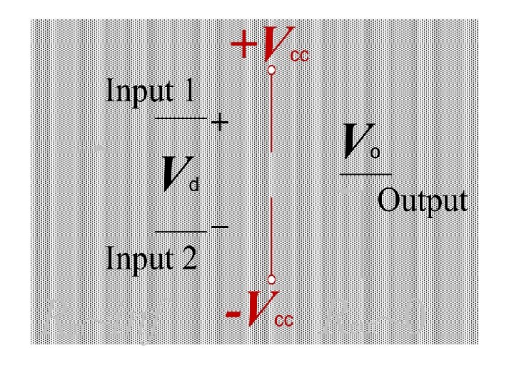
Common-Mode Rejection Ratio (CMRR) Differential voltage input : Common-mode rejection ratio: Output voltage : Gd : Differential gain Gc : Common mode gain Note: When Gd >> Gc or CMRR Vo = G d Vd 39
CMRR Example What is the CMRR? Solution : (1) (2) NB: This method is Not work! Why? 40
Applications of Op-Amp n To provide voltage amplitude changes (amplitude and polarity) n Comparators n Oscillators n Filters n Sensors n Instrumentation amplifiers 41