Upper mantle flow associated with plate motion and


 Vertical")


")


 & observed (white bars) SKS splitting Gray wedge indicates")
")


")


- Slides: 39
• • Upper mantle flow associated with plate motion and melt-enhanced upwelling Influences of ridge segmentation & asymmetric opening • Development of mantle seismic anisotropy • Modeling flow-induced anisotropy • Ideas for further work in Gulf of California
• Plate-driven mantle flow • Upwelling and decompression melting of peridotite • • Buoyancy-enhanced upwelling if melt is retained within crystal matrix Spreading rate (and/or regional viscosity) control on nature of flow and, therefore, the rate/structure of new crust produced
Motion of plates induces flow in upper mantle Decompression melting Along-strike variation in melt production and/or migration >> stronger flow velocity gradients
• • Evidence of 3 -D upwelling and/or melt supply? Variation in lithospheric structure • • • Cooling with age & changes in plate thickness at ridge offsets Central vs end-of-segment crustal structure? Evolution in time • • • Changes in rift/ridge-transform plate boundary geometry Response to change in plate motion? Reflection of changes in melt supply? (entrained heterogeneities) >>> degree of coupling between lithosphere and asthenosphere…
Van Wijk & Blackman, Tectonophysics, in press (basic results similar to earlier work by us/others) Top velocity (10 mm/yr, half rate), initial plate boundary position prescribed T-dependent viscosity, coupled deformation (finite element, Tekton revised for 3 -D) & temperature (finite difference) calculation Axial zone is weak Visco-elastic, power law rheology with separate upper crust, lower crust, & mantle properties Melt production follows Mc. Kenzie & Bickle 1988 Axial zone ~2 orders of magnitude weaker than surrounding lithosphere
kilometers Non-transform offset Map View top 55 km top transform offset (free slip) Vertical Profile Depth (km) mm/yr km 12 km W of axis km 45 km W of axis
Transform offset kilometers Map View, 20 km depth kilometers Melt buoyancy enhanced upwelling Small component of along-strike flow near segment end
Map View Vertical Profiles along spreading axis
• • Mantle minerals have inherently anisotropic elastic structure Flow-induced alignment of crystal orientations • • • Poly-crystalline aggregates undergo deformation Possible contribution of retained/migrating melt • Distribution of melt >> anisotropic signature • Influence on bulk seismic velocity Effective elastic constants & modeling surface seismic signature
Development of mineral texture along flowlines Strain-induced alignment of mineral grains Distribution of grain orientations Peridotite is olivine (black poles) + pyroxene (green poles), ~70: 30
ol 1341 Compute Effective Elastic Constants Voigt average over all the individual grain contibutions Oriented single-crystal EC projected onto global frame to get x, y, z contribution en 1341 ol 1322 en 1322
ol 1341 Compute Effective Elastic Constants Voigt average over all the individual grain contibutions Oriented single-crystal EC projected onto global frame to get x, y, z contribution en 1341 Fast direction Magnitude anisotropy ol 1322 en 1322
Buoyancy Enhanced Upwelling predicted body-wave anomaly due solely to presence of melt relative travel time delay (secs) Passive Flow Model symbols show different models of melt 'inclusion' geometry (Blackman & Kendall, 1997)
Passive vs. Buoyancy-Enhanced Upwelling slow, symmetric spreading Flowlines & finite strain P-wave anisotropy (degree & fast-axis direction)
• • East Pacific Rise • MELT Experiment 17°S • Suite of models & comparison with OBS data Western US • • Mantle Wedge flow behind subducting plate • • CSEDI Project with Thorsten Becker & Vera Schulte-Pelkum With/without backarc shearing Proposal for Gulf of California • Collaboration with Frank Vernon & Graham Kent, Harold Magistrale, & Gary Pavlis
Shear Wave Splitting determined along the MELT OBS array (Wolfe et al. , Science 1998)
Finite strain P-Wave Anisotropy Maximu S Splitting Mnimum S Splitting Reference EPR 17°S Flow Model Migrates 32 mm/yr Constant asthenospheric viscosity S Splitting at Vertical Incidence
Flow across 600 km depth is not allowed Flowlines & finite strain P-wave anisotropy S-wave Splitting at nearvertical incidence Incidence + 20° Incidence - 20°
Temperature Anomaly associated with Pacific Superswell influences flow (Toomey et al. , EPSL 2002) Predictions for seismic anisotropy & heterogeneity match MELT data better than the other models tested
Subduction Zone Anisotropy Direction of fast-seismic propagation has been determined to parallel the trench in several cases Broadscale mantle flow? Backarc shearing (Hall et al. , 2000)? Effect of water on fastaxis orientation during texturing (Jung & Karato, 2001)?
2 -D Corner Flow Add Along-trench Flow P-wave anisotropy max S- wave Splitting Vertical Swave Splitting
Mantle flow and predicted anisotropy in the Lau Basin Conder et al. , GRL 2002 Backarc spreading flow and melting in addition to subduction-induced mantle wedge flow
Western US Finite Strain Ellipses Becker et al, EPSL submitted 2005 Color-coded for depth Surface velocity condition (white arrows), global seismic tomography proxy for density, radially varying viscosity, Kaminsky & Ribe method for LPO Profile view of finite strain Predicted Fast S Polarization Direction (black bar)
Comparison of predicted (black bars) & observed (white bars) SKS splitting Gray wedge indicates variation in prediction due to method of synthetic calculation (single layer approximates 375 km deep region vs. multiple, variable layers) Western US initial results Overall fit is reasonable for central/southern area. NW and Basin & Range are not matched well. Local structure & effects on flow (not included in low resolution global model) preclude match in complex areas (S Great Valley)
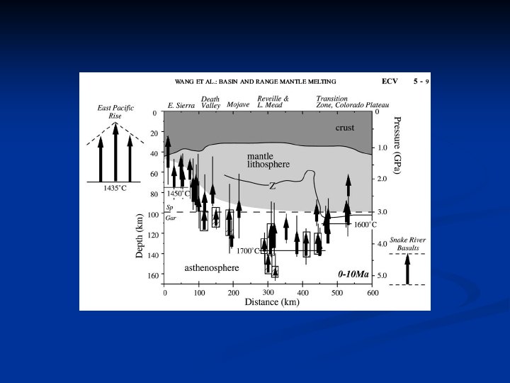
Relation to complete crustal transect? Anomalously hot? Depth extent of upwelling? Southern (oceanic spreading) vs. Northern (rifting) Gulf structure? Buoyancy vs platedriven flow? Gaherty, Collins, Rebollar surface wave study designed to address several aspects Continue to pursue additional work (SIO, SDSU, CICESE, Indiana)
Seismometer Deployments NARS ~5 yr, 18 broadband Collins et al. OBS ~15 mo, 18 broadband Proposed Array 60 PASSCAL 22 OBS All broadband 15 -18 months
Seismometer Deployments NARS ~5 yr, 18 broadband Collins et al. OBS ~15 mo, 18 broadband Previously Proposed Array 60 PASSCAL 22 OBS All broadband 15 -18 months
1. 2. Architecture of the crust across the rift system • Teleseismic and local event tomography • Mapping of Moho across onshore & offshore parts of system • Local EQ source parameters Strength and deformation of the lower crust • 3. Imaging of forward scattered P-S conversions Upper mantle thermal structure and flow • seismic velocity structure & attenuation (scale of ~10 km) • Shape of seismic discontinuities (upward or downward deflection? ) • Seismic anisotropy (splitting, polarization direction of fast S wave) • Linked models of mantle flow, lithospheric deformation, development of textural (+/- melt) anisotropy, and seismic anisotropy • Converted phase imaging for detecting possible foundered slab Coordinate with findings of other Gulf of CA studies
(Poppeliers & Pavlis, 2002)
1. 2. Architecture of the crust across the rift system • Teleseismic and local event tomography • Mapping of Moho across onshore & offshore parts of system • Local EQ source parameters Strength and deformation of the lower crust • 3. Imaging of forward scattered P-S conversions Upper mantle thermal structure and flow • seismic velocity structure & attenuation (scale of ~10 km) • Shape of seismic discontinuities (upward or downward deflection? ) • Seismic anisotropy (splitting, polarization direction of fast S wave) • Linked models of mantle flow, lithospheric deformation, development of textural (+/- melt) anisotropy, and seismic anisotropy • Converted phase imaging for detecting possible foundered slab Coordinate with findings of other Gulf of CA studies
Jones et al. , 1994
• • Mantle structure & flow are likely to vary both laterally and with depth on scale of several km • Along-strike changes in Go. C rifting • Influence of transform offsets • Large scale flow at depth Combination of research approaches needed to fully address problems • • • Separate effects of T, melt, textural anisotropy Series of inverse studies and selected forward modeling tests to assess possible contributions of various structure and implied geodynamic consequences Opportunity to assess both crust & mantle structure to infer processes of rifting as a full system • Combine body wave, surface wave and active source seismics • Current data will provide resolution of mantle on several 10 ‘s km scale • Denser onshore/OBS array would improve resolution to several km • • Avoid ‘bias’ due to possible superpostion of segmentation and longer wavelength rifting signatures Recognize cross-axis structure which could be key to understanding rifting processes
Key Constraints Needed • • Surface velocity • Plate boundary geometry, temporal evolution Cooling rates of crustal rocks Caution about • Guide vertical flow predictions possible ‘bias’ due to limited Information on melting areas (core • Degree/depth of melting complexes) emphasized in • Composition many studies … Seismic/EM measurements • All phases (P, S, Surface Waves) • As many backazimuths & angles of incidence as possible
Savage & Sheehan, 2000
Pole Figures illustrate development of texture Texture predicted depends on assumptions but fundamental result is often similar between methods Wenk & Tomé, JGR 1999, model recrystallization via strain-controlled nucleation & growth of new grains Sub-vertical shear imparts strong texture in upwelling zone; diffusion occurs in corner; subhorizontal shear generates plate-spreading signature
P-wave anisotropy along flowline: different models
Comparison of Texture & Finite Strain Anisotropy Prediction P-wave fast axis orientation for slow-spreading, passive model