Upgraded Injector Test Facility UITF Personnel Safety Systems
 Personnel Safety Systems H. Robertson May 2016")


 emitted")


")


- Slides: 33
Upgraded Injector Test Facility (UITF) Personnel Safety Systems H. Robertson May 2016
Introduction • The UITF is a new test facility • Operation of 450 KV 3 m. A photoemission electron gun • performs electron beam studies and support of other experiments including physics targets, etc. • It is located in the former Injector Test Stand (ITS) area at the east wall of the Test Lab building.
Scope The scope of this presentation is to describe the intended facility and its hazards, and show each hazard, not already minimized by other methods, will be mitigated by the Personnel Safety System (PSS) or the Oxygen Monitoring System (ODH).
Site Description • Environment: – 1 entry door, 2 egress points • Sliding steel cage door – west wall of vault 2 • Standard hinged rear door – south wall of vault 1 – Removable roof sections – Permanent passive roof vent – Continuous air flow through the original venting system and wire mesh entrance gate
Upgraded Injector Test Facility - UITF
Mandated Requirements stemming from DOE orders and JLab EH&S Policy. SAD 1 The PSS shall be designed and operated in a manner consistent with the approved Operations and Safety envelopes. SAD 2 Other PSS systems shall be designed and operated to meet the applicable sections of the JLab EH&S manual. SAD 3 PSS systems shall be certified and tested at an interval consistent to meet regulatory requirements. In the event of a conflict the more conservative test interval shall be used. SAD 4 Personnel performing administrative PSS procedures shall be trained and certified as competent to perform the procedures. SAD 5 Personnel Safety Systems supervising secured PSS areas shall be under the control of trained and certified personnel at all times. SAD 6 The PSS shall meet or exceed the fail-safe requirements. SAD 7 Personnel Safety Systems shall be able to carry out the intended safety functions with a full functional failure of one leg of a redundant (1 oo 2) system. SAD 8 PSS design and implementations shall be robust against common mode failures. SAD 9 Operations shall be suspended in any area where a PSS function or device is suspected of being defective or compromised. Operations shall not recommence until the problem is fixed and recertified or it is determined that the PSS is performing as designed.
General Requirements GR 1 The PSS shall provide access control, interlock, and alarm devices, which when coupled with other safety layers, reduce the risk of a defined accident to risk code 0 or 1. GR 2 Critical devices shall be used to prohibit beam transport from an operational area to an occupied area. GR 3 A PSS access control system (ACS) shall be used to establish and maintain barriers between personnel and operational hazards. GR 4 A PSS Safety Interlock System (SIS) shall be used to mitigate personnel exposure to hazardous energy from devices interlocked through the PSS. GR 5 The determination of the inclusion or exclusion of devices interlocked through the PSS shall be made during the hazard assessment for each facility. GR 6 Primary Safety Systems shall fail to a safe state or condition. GR 7 The fail-safe state for each PSS device and interface shall be defined. GR 8 Unless otherwise justified in writing, the fail-safe state of PSS controls shall be zero volts. GR 9 The status of any hazardous device which is interlocked through the PSS shall be sensed by the PSS.
General Requirements GR 10 If the indicated status of a hazardous device does not agree with the permitted PSS state, the PSS shall default to the fail-safe state. GR 11 PSS systems for a PSS operational segment (areas) shall have control over all devices which could present a hazard to the segment or control over critical devices that protect the segment. GR 12 The PSS shall provide a means for human initiated emergency shutdown of all hazardous equipment that can affect an access control area (e. g. E-STOP). GR 13 The PSS shall be robust against common failure modes including loss of power, short or open circuits, communication errors, and mechanical damage. GR 14 The PSS mean time to repair shall be consistent with the specified safety availability.
Access Control Requirements AC 1 The PSS shall facilitate establishing and maintaining secure access and exclusion areas. AC 2 The PSS shall monitor the status of all doors that allow access to secure areas. AC 3 No access to a radiation enclosure shall be permitted in an “exclusion” state. If any interlocked door is opened while the PSS is in an “exclusion” state, the PSS system will drop. AC 4 The PSS shall logically require establishing an exclusion area in the beam enclosure prior to permitting operation of a hazardous device. AC 5 The PSS shall remove permits to hazardous devices upon detection of an unauthorized entry to a secure area. AC 6 The establishment of an exclusion area shall require a visual search and secure (Sweep) of the beam enclosure. AC 7 The search and secure pattern (Sweep) shall follow a designated pattern designed to ensure all beam enclosure areas are observed. AC 8 The PSS shall provide clearly visible status indicators of the “Safe” or potentially “Unsafe” status within the beam enclosure. AC 9 The PSS shall provide an audible warning before transitioning from a “Safe” state to an “Unsafe” state. AC 10 The PSS shall provide clearly visible status or warning indicators outside of each entrance to the beam enclosure. The status indicators shall be an indication of a potential radiation area.
Access Control Requirements AC 11 The only designated access points to a secure enclosure shall be through dedicated access areas. All other doors shall be considered as “emergency exit only. ” AC 12 During a sweep or controlled access only one of the two access doors may be in the open position. Both doors open simultaneously shall be considered a breach of the enclosure, resulting in a drop to the safest state. AC 13 Secure access points shall be equipped with PSS door interlocks, interlocked exchange tokens, communication, and remote monitoring equipment. AC 14 The PSS shall impede entry into an exclusion area by use of electrical or mechanical door locks. AC 15 All electrical locks shall automatically engage when the PSS is in an “Unsafe” state. AC 16 Unless justified in writing, PSS access controls shall not impede life-safety egress from a beam enclosure. AC 17 AC 18 AC 19 AC 20 AC 21
Interlock Requirements SIS 1 Unless justified in writing, the SIS shall be implemented with 2 independent (redundant) chains with 1 out of 2 (1 oo 2) shutdown capability. SIS 2 The two SIS divisions (chains) shall extend from the sensor to the final device. SIS 3 Each division shall remain independent of the other from the field sensing device up to the final control element. SIS 4 Control and status signals of any equipment not under the direct configuration control of the PSS group shall be electrically isolated from SIS equipment. SIS 5 SIS equipment and wiring shall be located in dedicated PSS racks, conduit, or cable tray. SIS 6 All SIS interlock functions shall be safe against single chain undetected failures. SIS 7 No single chain failure shall result in the ability to energize a hazardous device while personnel may be exposed to a hazard otherwise mitigated by the SIS 8 The SIS system shall be designed to reduce the risk of hazards resulting from unauthorized access to an enclosure to a risk level 0 – Little to no consequences/Extremely unlikely. SIS 9 The SIS system shall be designed to reduce the risk of exposure to high power microwave radiation to level 0 – Little to no consequences/Extremely unlikely. SIS 10 The SIS shall not be used to provide the normal on/off control of an interlocked device. SIS 11 The PSS shall not automatically reset once a tripped interlock is restored. A manual reset by a qualified operator is required.
PSS Equipment Protection / Isolation • Locked, isolated racks • Separate conduits / boxduct • Isolated interfaces to Gun HVPS, Laser, and RF systems
Hazards Prompt ionizing radiation due to high power beam operations Mitigation: • • • Gun High Voltage Power Supplies (HVPS) permits: – AC contactor (direct) – HVPS “Enable” circuit (direct) Laser permits: – Macro. Pulse (pockels cell) control – Shutter control (direct) Required conditions: – Cave in “Run” state (exclusion mode) – All CARM status = OK – Beam current within limits
Hazards Prompt ionizing radiation due to RF cavity field emission RF radiation (non-ionizing) emitted from waveguide joints or open sections (over 5 m. W/cm 2) Mitigation: RF High Voltage Power Supplies (HVPS) permits require: – Cave in “Run” state (exclusion mode) – All CARM status = OK – Waveguide pressure status?
Hazards Eye hazard due to accidental exposure to drive laser light when the vault is in laser alignment mode Mitigation: Assumption: CIS staff will develop safety controls for all possible lasing conditions Gun HVPS ON when the during laser alignment Mitigation: Laser Bypass switch will allow laser alignment and disable Gun HVPS in the “Bypass” position
Hazards Poisoning by SF 6. Mitigation: Assumption: CIS staff will design, install, and maintain SF 6 controls and safety requirements Over pressurization of the SF 6 vessels. Mitigation: Assumption: CIS staff will design, install, and maintain SF 6 controls and safety requirements
Hazards ODH - Oxygen deficiency hazard resulting from a gas/liquid release in the vault. UITF has been evaluated and is designated an ODH 0 area. Mitigation: • Fixed monitoring system (3 sensors) • Audible and visual warnings – within the cave – at each entrance – in the Control Room
Interfaces The PSS will provide “Run” mode permits to Gun HVPS control chassis, Laser control chassis, and shutters – The CIS group will provide an interface to the Macro. Pulse circuits. The PSS will provide “Run” mode permits to RF HVPSs contactor and clamping circuits – The RF group will provide connections for contactor control and output status (or the PSS will use its own contactor) The Radiation Control Group will provide CARMs/probes with PSS interlock connections
Special Requirements After the UITF is in the Run state there must be a 30 second time delay before the Gun or RF HVPS or the Laser can be enabled CARM faults drop PSS permits (Gun, RF, Laser), but not the PSS “Run” state
Assumptions Fixed and removable shielding - i. e. concrete and steel walls, doors, vents and blocks - are adequate to meet all safety requirements that are not protected by functions of the PSS
Trip Functions Drop RUN state Drop Sweep Complete Shut off Gun Permits Shut off RF Permits Shut off Laser Permits Insert Shutters ACTION TAKEN Access Control Fault ü ü ü ESTOP Crash ü ü ü ü ü FAULT Status of Interlocked Device inconsistent with PSS State RF Waveguide Interlock Fault Radiation Monitor Alarm ü
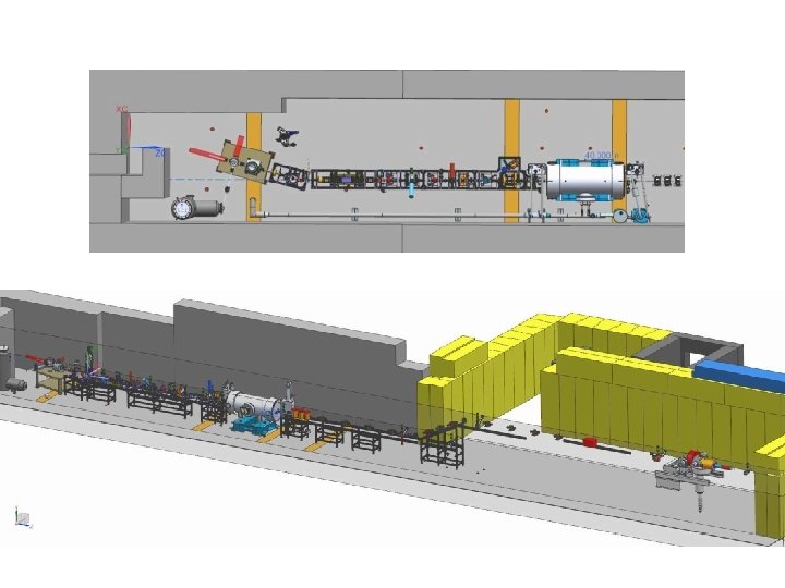
VAULT EQUIPMENT LAYOUT FOR PSS AND ODH
PSS RACKS ON UITF MEZZANINE (17, 18)
PSS Racks
Architecture System A PLC Master Drop w/ Local I/O Remote I/O Network Remote I/O Drop 24 VDC Device System B PLC Master Drop w/ Local I/O 24 VDC Remote I/O Drop Remote I/O Network
Architecture Sensor Status Isolation Permissive Isolation Input Module Output Module Main Processor Module PLC A Controlled Device Control Circuit Isolation Permissive Sensor Status Isolation Output Module Input Module PLC B Main Processor Module
Operational Modes Open State – No Gun or RF HVPS permitted – Laser permitted only in “Bypass” laser alignment mode Sweep State – No Gun or RF HVPS permitted – Sliding steel gate and rear door must be fully closed when sweep complete
Operational Modes Run State – – – – – Area must be swept and secured Gun / RF HVPS permitted (30 second delay) Sliding gate closed Rear door closed Crash buttons active Audible warnings (for 30 seconds) Visible warnings (continuous) CARMs active Sweep Key in RUN position
Internal Mode Ready State = Sweep Complete • Not Open • Not Sweep • Not Run
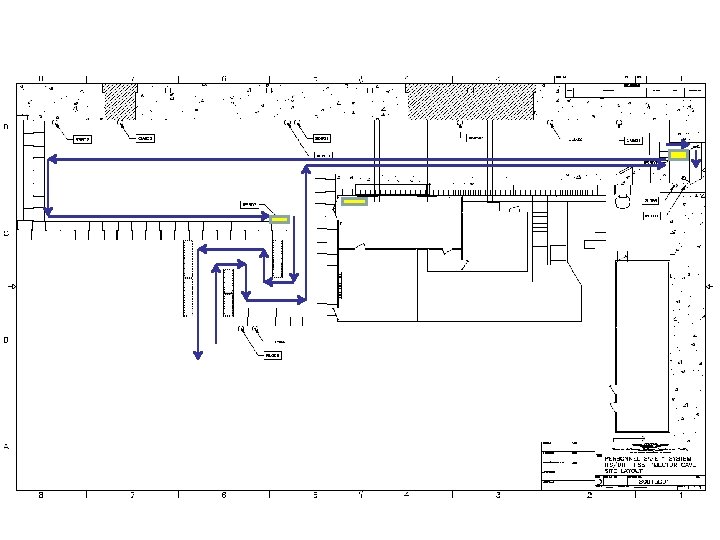
Sweep/Secure Process – Two sweepers are required – Sweep key will be kept in PSS interface panel (UITF control room) – Sweep Key is switched to “Sweep” mode to start – Sweep includes Run/Safe Boxes 01 and 02 • Sequence = RS 02, then RS 01 – Upon arming RS 01, close steel gate and exit (30 seconds) – Sweep Key is returned to PSS panel and switched to “Run” to begin operations
Any questions?