
Update on voltage calculations Tiina Salmi and Antti

- Slides: 23
Update on voltage calculations Tiina Salmi and Antti Stenvall, Tampere University of Technology (TUT) 11. 3. 2016 With contibution from Janne Ruuskanen and Valtteri Lahtinen, TUT T. Salmi, TUT 1
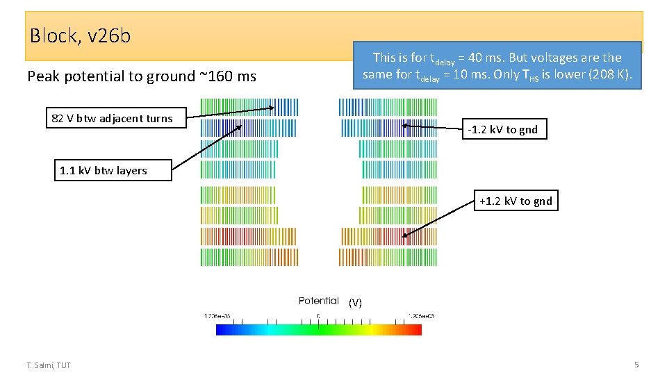
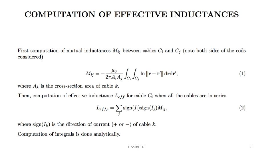
Status • Last time showed preliminary voltage calculation for Cos. Theta and Block designs. Now have done checks and improvement to the code for more reliable results • Last time the magnet inductive voltage was divided evenly for all coil turns. Now the mutual inductance matrix is computed using a separete software and the inductive voltage is distributed to the turns according to their contribution to the total (differential) inductance. • The inductance calculation is thanks to our student Janne Ruuskanen – Team effort! • Details in appedix • I made a comparison with ROXIE quench module considering the costheta – The temperature and voltage distribution in the turns is in good agreement (inductive + resistive). • Worked together with Susana on this • More details in the appendix • I repeated the voltage analysis for all 3 design options. I will show the resulting voltages – they are smaller than in the presentation last time, not only because new inductance computations but also because of new designs. • Final slide has a summary table of the temperatures and voltages in all desings T. Salmi, TUT 2
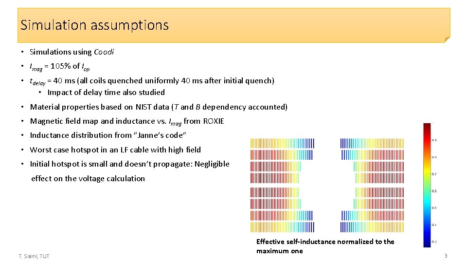
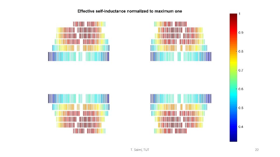
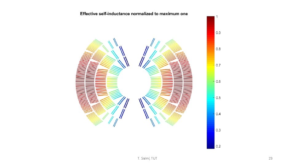
Simulation assumptions • Simulations using Coodi • Imag = 105% of Iop • tdelay = 40 ms (all coils quenched uniformly 40 ms after initial quench) • Impact of delay time also studied • Material properties based on NIST data (T and B dependency accounted) • Magnetic field map and inductance vs. Imag from ROXIE • Inductance distribution from ”Janne’s code” • Worst case hotspot in an LF cable with high field • Initial hotspot is small and doesn’t propagate: Negligible effect on the voltage calculation T. Salmi, TUT Effective self-inductance normalized to the maximum one 3
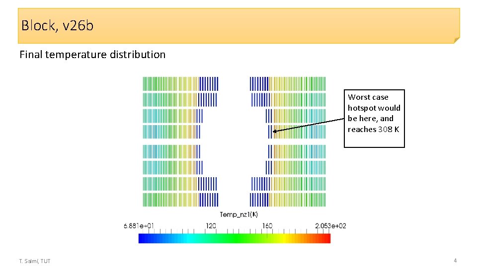
Block, v 26 b Final temperature distribution Worst case hotspot would be here, and reaches 308 K (K) T. Salmi, TUT 4
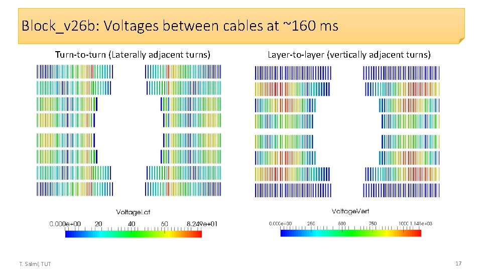
Block, v 26 b This is for tdelay = 40 ms. But voltages are the same for tdelay = 10 ms. Only THS is lower (208 K). Peak potential to ground ~160 ms 82 V btw adjacent turns -1. 2 k. V to gnd 1. 1 k. V btw layers +1. 2 k. V to gnd (V) T. Salmi, TUT 5
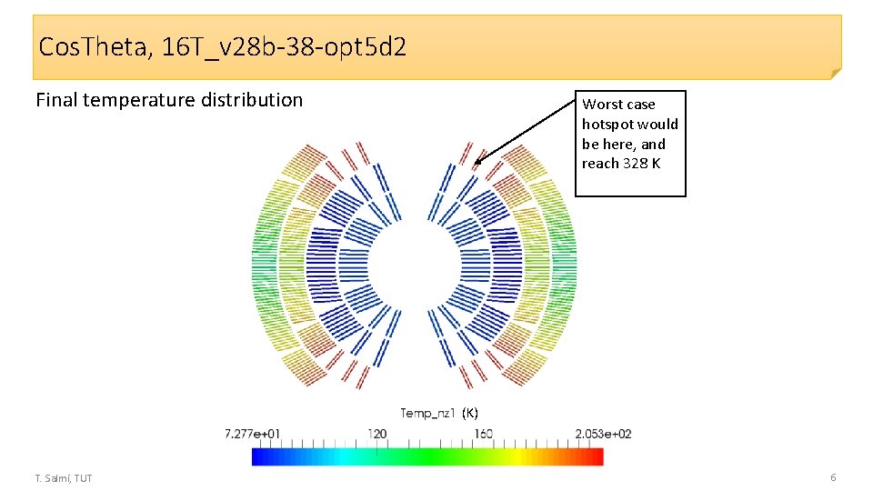
Cos. Theta, 16 T_v 28 b-38 -opt 5 d 2 Final temperature distribution Worst case hotspot would be here, and reach 328 K (K) T. Salmi, TUT 6
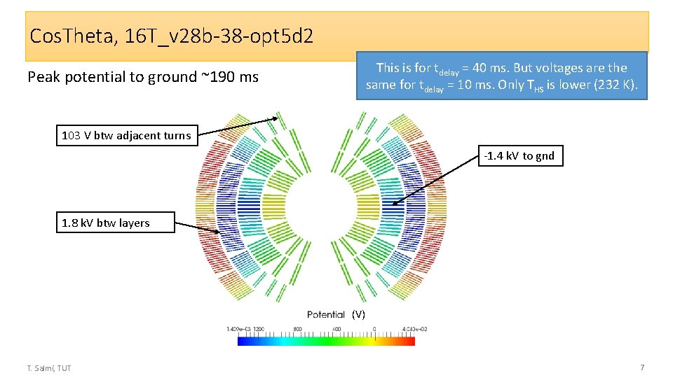
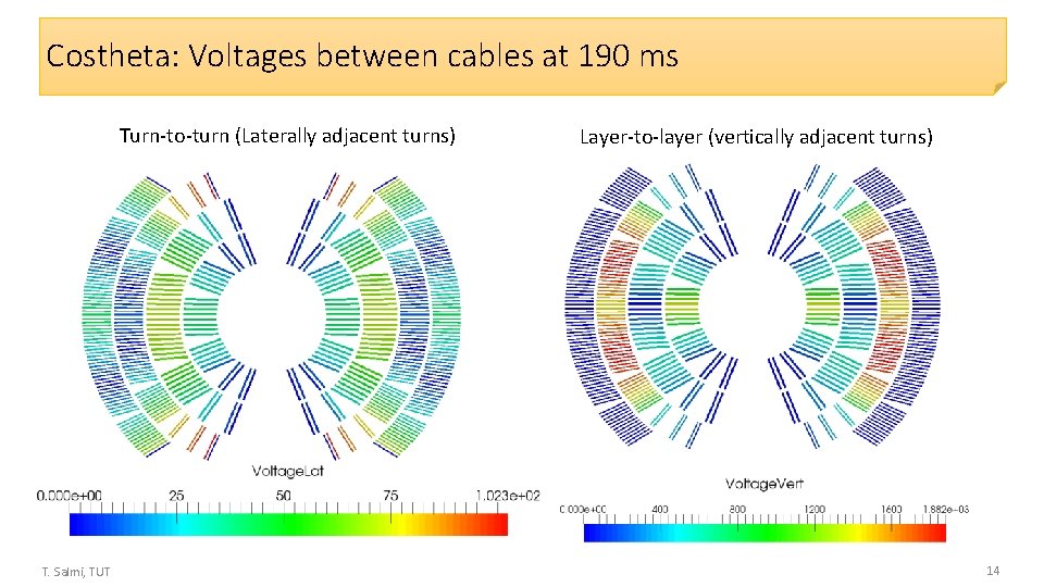
Cos. Theta, 16 T_v 28 b-38 -opt 5 d 2 This is for tdelay = 40 ms. But voltages are the same for tdelay = 10 ms. Only THS is lower (232 K). Peak potential to ground ~190 ms 103 V btw adjacent turns -1. 4 k. V to gnd 1. 8 k. V btw layers (V) T. Salmi, TUT 7
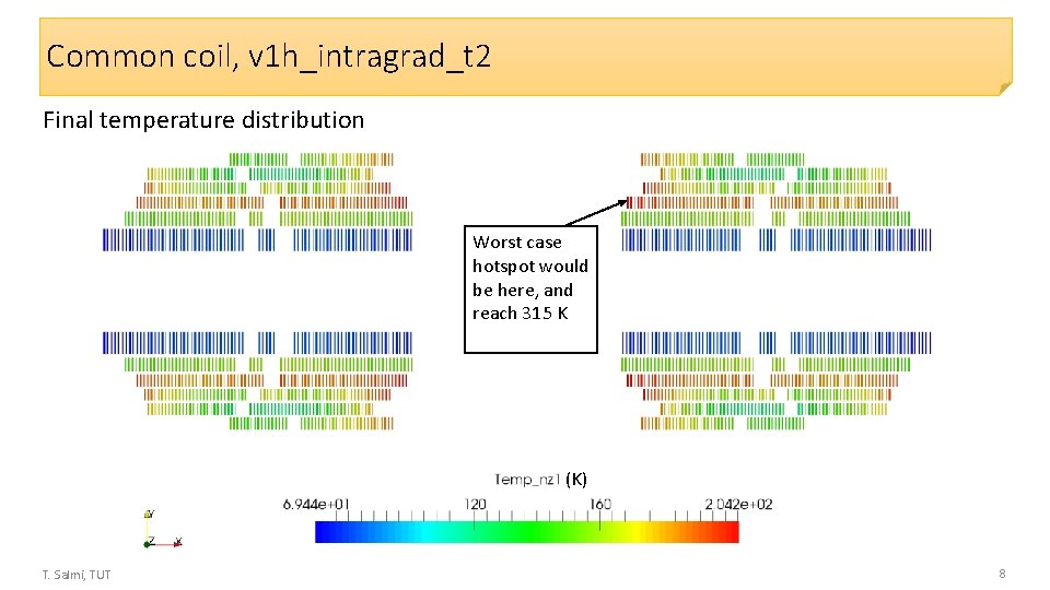
Common coil, v 1 h_intragrad_t 2 Final temperature distribution Worst case hotspot would be here, and reach 315 K (K) T. Salmi, TUT 8
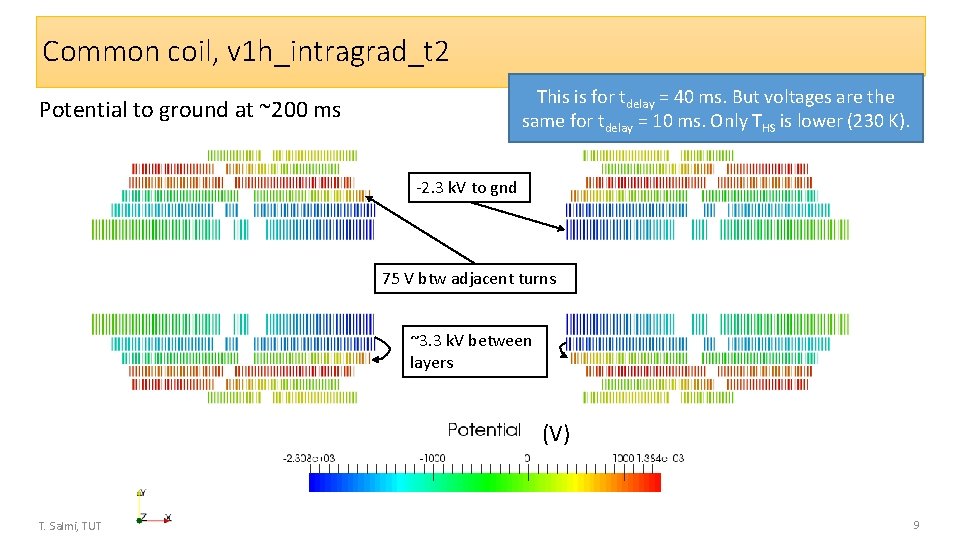
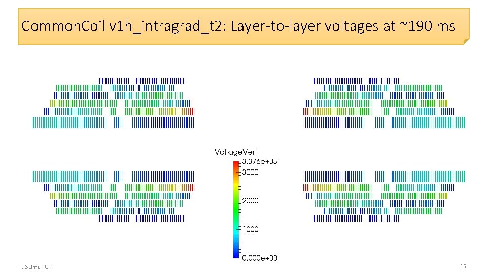
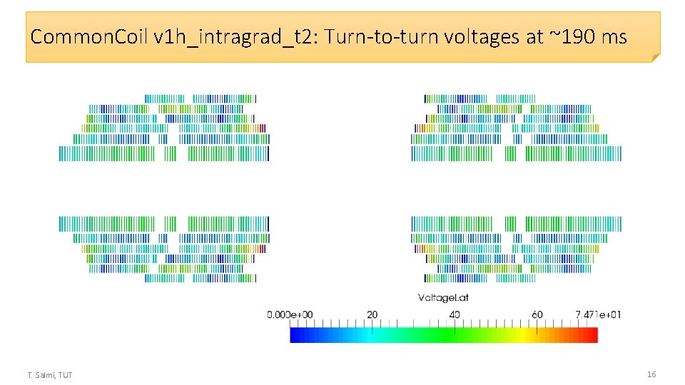
Common coil, v 1 h_intragrad_t 2 This is for tdelay = 40 ms. But voltages are the same for tdelay = 10 ms. Only THS is lower (230 K). Potential to ground at ~200 ms -2. 3 k. V to gnd 75 V btw adjacent turns ~3. 3 k. V between layers (V) T. Salmi, TUT 9
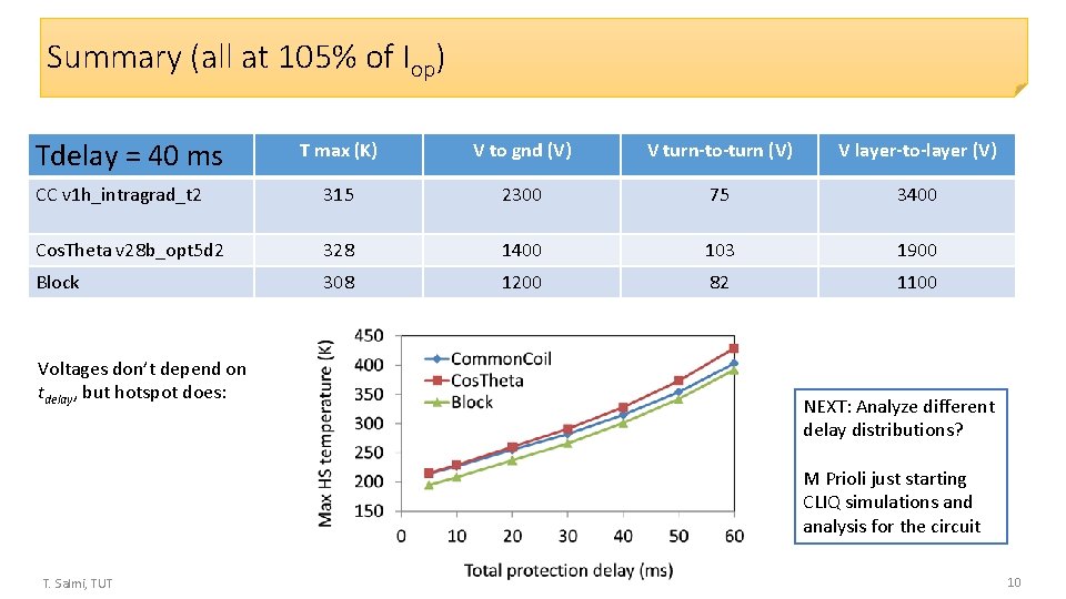
Summary (all at 105% of Iop) Tdelay = 40 ms T max (K) V to gnd (V) V turn-to-turn (V) V layer-to-layer (V) CC v 1 h_intragrad_t 2 315 2300 75 3400 Cos. Theta v 28 b_opt 5 d 2 328 1400 103 1900 Block 308 1200 82 1100 Voltages don’t depend on tdelay, but hotspot does: NEXT: Analyze different delay distributions? M Prioli just starting CLIQ simulations and analysis for the circuit T. Salmi, TUT 10
Appendix T. Salmi, TUT 11
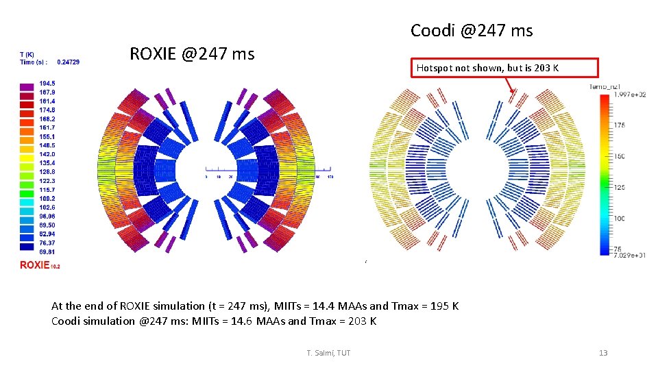
Voltage comparison with ROXIE T. Salmi, TUT 12
Coodi @247 ms ROXIE @247 ms Hotspot not shown, but is 203 K At the end of ROXIE simulation (t = 247 ms), MIITs = 14. 4 MAAs and Tmax = 195 K Coodi simulation @247 ms: MIITs = 14. 6 MAAs and Tmax = 203 K T. Salmi, TUT 13
Costheta: Voltages between cables at 190 ms Turn-to-turn (Laterally adjacent turns) T. Salmi, TUT Layer-to-layer (vertically adjacent turns) 14
Common. Coil v 1 h_intragrad_t 2: Layer-to-layer voltages at ~190 ms T. Salmi, TUT 15
Common. Coil v 1 h_intragrad_t 2: Turn-to-turn voltages at ~190 ms T. Salmi, TUT 16
Block_v 26 b: Voltages between cables at ~160 ms Turn-to-turn (Laterally adjacent turns) T. Salmi, TUT Layer-to-layer (vertically adjacent turns) 17
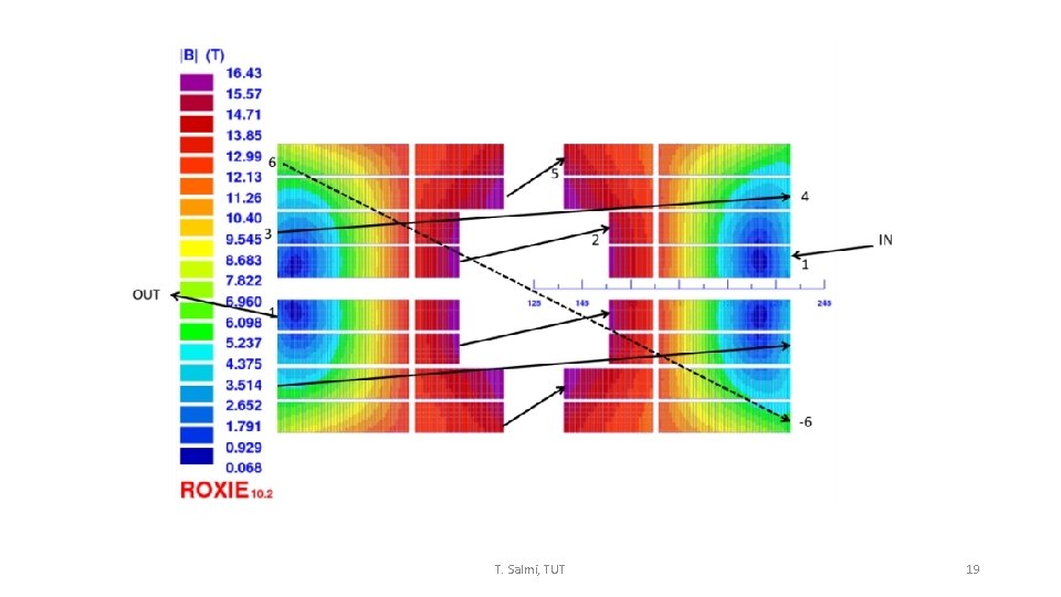
IN OUT T. Salmi, TUT 18
T. Salmi, TUT 19
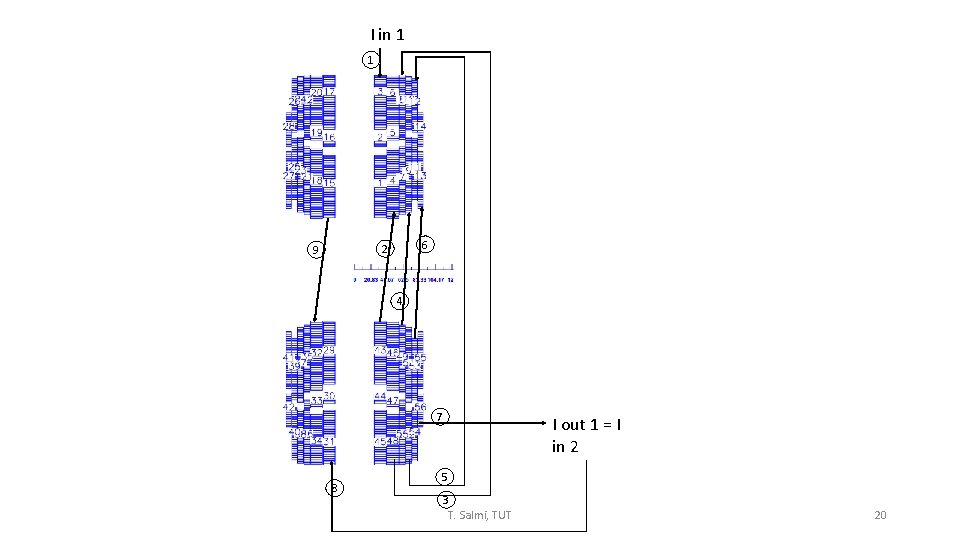
I in 1 1 6 2 9 4 7 8 I out 1 = I in 2 5 3 T. Salmi, TUT 20
T. Salmi, TUT 21
T. Salmi, TUT 22
T. Salmi, TUT 23