
Update on stave thermal testing Claudio BORTOLIN Enrico
Update on stave thermal testing Claudio BORTOLIN Enrico DA RIVA Corrado GARGIULO Manuel GOMEZ MARZOA WG 4 Meeting - 12 th December 2012 M. Gomez Marzoa WG 4 Meeting - 12 th December 2012 1
Contents 1. Overview 2. Wound-truss prototypes plus carbon plate with embedded pipes: thermal tests § D 12: non-squeezed pipes 3. Results: § @0. 3 W cm-2 & @0. 5 W cm-2 § D 12 (C 4 F 10) vs. D 06 (water) § D 12 vs. D 08 (C 4 F 10) § Summary plot 4. General conclusion & test plan M. Gomez Marzoa WG 4 Meeting - 12 th December 2012 2
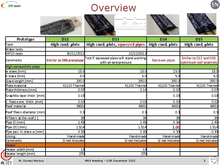
Overview Prototype Type Water tests C 4 F 10 tests Comments High conductivity plate w stave [mm] h stave [mm] Stave length [mm] Plate material Plate thickness [mm] D 12 High cond. plate 30/11/2012 D 13 D 14 High cond. plate, squeezed pipes High cond. plate 10/12/2012 Test if squeezed pipes will stand working Similar to D 06 prototype with an overpressure 15. 0 290. 0 K 1100 Thornel 0. 07 0. 14 - D 15 High cond. plate Similar to D 12 and D 06, Narrower pipes optimized roof assembly 15. 0 290. 0 K 1100 Thornel 0. 07 Graphite layer thick. [mm] 0. 03 - 0. 03 C. fleece enc. thick. [mm] Roof material 0. 02 M 60 J 0. 3 38 1. 45 1. 514 0. 33 Hand-made Si not included 13 270 38 9. 36 38 1. 45 1. 514 0. 33 Hand-made Si not included Roof fibers diameter [mm] N fibers at the roof [-] Pipe ID [mm] Pipe OD [mm] Pipe pos. in stave w [mm] Gluing Comments Heater width [mm] Heater length [mm] M. Gomez Marzoa 13 270 WG 4 Meeting - 12 th December 2012 1. 00 0. 33 Hand-made Si not included 3
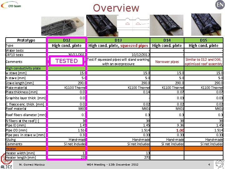
Overview Prototype Type Water tests C 4 F 10 tests Comments High conductivity plate w stave [mm] h stave [mm] Stave length [mm] Plate material Plate thickness [mm] D 12 High cond. plate 30/11/2012 D 13 D 14 High cond. plate, squeezed pipes High cond. plate 10/12/2012 Test if squeezed pipes will stand working Similar to D 06 prototype TESTED with an overpressure 15. 0 290. 0 K 1100 Thornel 0. 07 0. 14 - D 15 High cond. plate Similar to D 12 and D 06, Narrower pipes optimized roof assembly 15. 0 290. 0 K 1100 Thornel 0. 07 Graphite layer thick. [mm] 0. 03 - 0. 03 C. fleece enc. thick. [mm] Roof material 0. 02 M 60 J 0. 3 38 1. 45 1. 514 0. 33 Hand-made Si not included 13 270 38 9. 36 38 1. 45 1. 514 0. 33 Hand-made Si not included Roof fibers diameter [mm] N fibers at the roof [-] Pipe ID [mm] Pipe OD [mm] Pipe pos. in stave w [mm] Gluing Comments Heater width [mm] Heater length [mm] M. Gomez Marzoa 13 270 WG 4 Meeting - 12 th December 2012 1. 00 0. 33 Hand-made Si not included 4
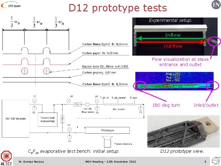
D 12 prototype tests Experimental setup. Inflow Outflow Flow visualization at stave entrance and outlet 180 deg turn C 4 F 10 evaporative test bench: initial setup. M. Gomez Marzoa WG 4 Meeting - 12 th December 2012 Inlet/outlet D 12 prototype view. 5
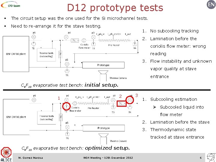
D 12 prototype tests § The circuit setup was the one used for the Si microchannel tests. Experimental setup. § Need to re-arrange it for the stave testing. 1. No subcooling tracking 2. Lamination before the coriolis flow meter: wrong reading 3. Flow instability and unknown vapor quality at stave entrance C 4 F 10 evaporative test bench: initial setup. 1 2 3 1. Subcooling estimation Ø Subcooled liquid into flow meter 2. Lamination before the stave 3. Thermodynamic state tracked at stave entrance C 4 F 10 evaporative test bench: optimized setup. M. Gomez Marzoa WG 4 Meeting - 12 th December 2012 6
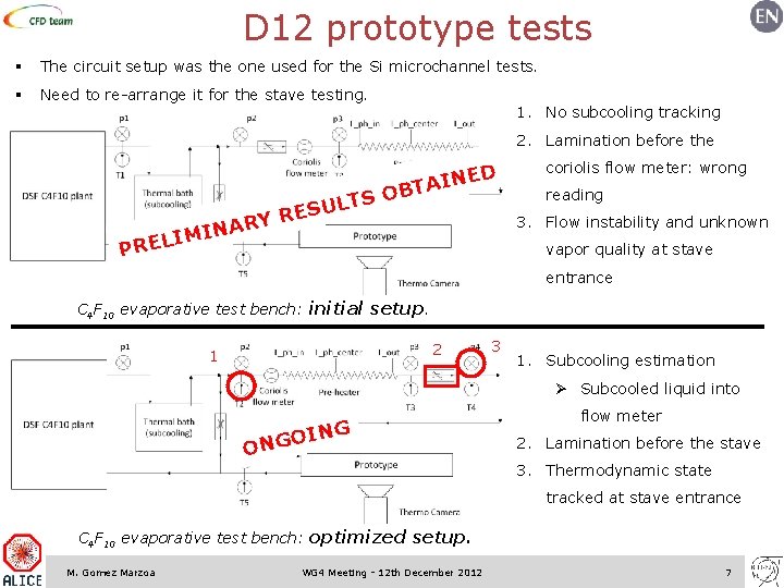
D 12 prototype tests § The circuit setup was the one used for the Si microchannel tests. Experimental setup. § Need to re-arrange it for the stave testing. 1. No subcooling tracking 2. Lamination before the NED I A T OB S T L RESU Y 3. R A N I M I PREL coriolis flow meter: wrong reading Flow instability and unknown vapor quality at stave entrance C 4 F 10 evaporative test bench: initial setup. 2 1 3 1. Subcooling estimation Ø Subcooled liquid into ING O ONG flow meter 2. Lamination before the stave 3. Thermodynamic state tracked at stave entrance C 4 F 10 evaporative test bench: optimized setup. M. Gomez Marzoa WG 4 Meeting - 12 th December 2012 7
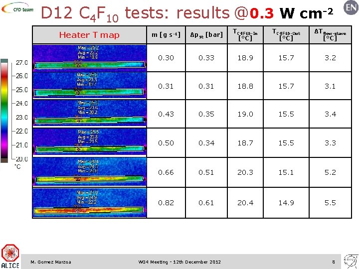
D 12 C 4 F 10 tests: results @0. 3 W cm-2 Heater T map M. Gomez Marzoa m [g s-1] Δp. St [bar] TC 4 F 10 -In [°C] TC 4 F 10 -Out [°C] ΔTflow-stave [°C] 0. 30 0. 33 18. 9 15. 7 3. 2 0. 31 18. 8 15. 7 3. 1 0. 43 0. 35 19. 0 15. 5 3. 4 0. 50 0. 34 18. 7 15. 5 3. 3 0. 66 0. 51 20. 3 15. 1 5. 2 0. 82 0. 61 20. 4 14. 9 5. 5 WG 4 Meeting - 12 th December 2012 8
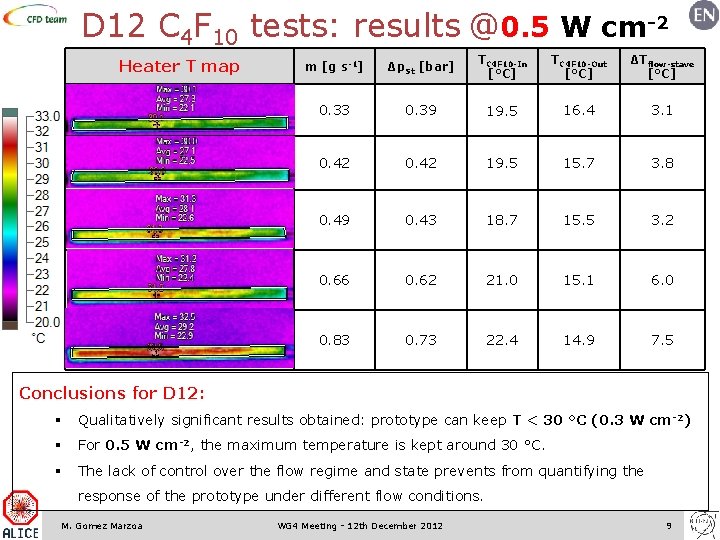
D 12 C 4 F 10 tests: results @0. 5 W cm-2 Heater T map m [g s-1] Δp. St [bar] TC 4 F 10 -In [°C] TC 4 F 10 -Out [°C] ΔTflow-stave [°C] 0. 33 0. 39 19. 5 16. 4 3. 1 0. 42 19. 5 15. 7 3. 8 0. 49 0. 43 18. 7 15. 5 3. 2 0. 66 0. 62 21. 0 15. 1 6. 0 0. 83 0. 73 22. 4 14. 9 7. 5 Conclusions for D 12: § Qualitatively significant results obtained: prototype can keep T < 30 °C (0. 3 W cm-2) § For 0. 5 W cm-2, the maximum temperature is kept around 30 °C. § The lack of control over the flow regime and state prevents from quantifying the response of the prototype under different flow conditions. M. Gomez Marzoa WG 4 Meeting - 12 th December 2012 9
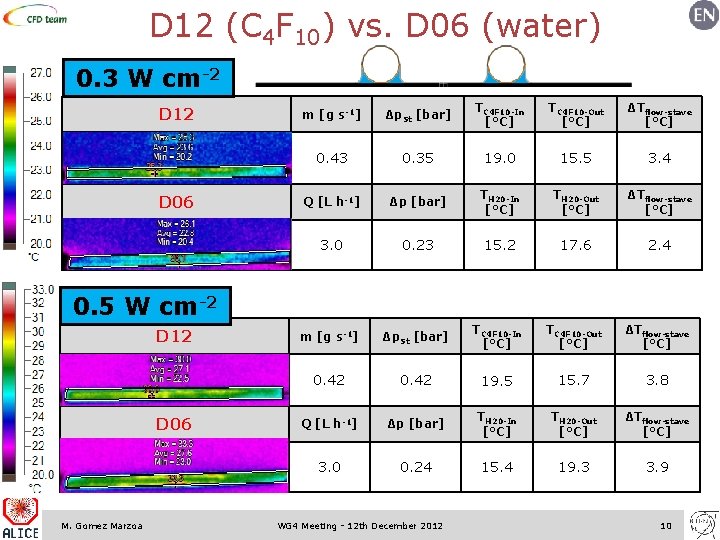
D 12 (C 4 F 10) vs. D 06 (water) 0. 3 W cm-2 D 12 D 06 m [g s-1] Δp. St [bar] TC 4 F 10 -In [°C] TC 4 F 10 -Out [°C] ΔTflow-stave [°C] 0. 43 0. 35 19. 0 15. 5 3. 4 Q [L h-1] Δp [bar] TH 20 -In [°C] TH 20 -Out [°C] ΔTflow-stave [°C] 3. 0 0. 23 15. 2 17. 6 2. 4 m [g s-1] Δp. St [bar] TC 4 F 10 -In [°C] TC 4 F 10 -Out [°C] ΔTflow-stave [°C] 0. 42 19. 5 15. 7 3. 8 Q [L h-1] Δp [bar] TH 20 -In [°C] TH 20 -Out [°C] ΔTflow-stave [°C] 3. 0 0. 24 15. 4 19. 3 3. 9 0. 5 W cm-2 D 12 D 06 M. Gomez Marzoa WG 4 Meeting - 12 th December 2012 10
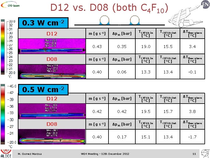
D 12 vs. D 08 (both C 4 F 10) 0. 3 W cm-2 D 12 D 08 m [g s-1] Δp. St [bar] TC 4 F 10 -In [°C] TC 4 F 10 -Out [°C] ΔTflow-stave [°C] 0. 43 0. 35 19. 0 15. 5 3. 4 m [g s-1] Δp. St [bar] TC 4 F 10 -In [°C] TC 4 F 10 -Out [°C] ΔTflow-stave [°C] 0. 40 0. 06 13. 3 13. 4 -0. 1 m [g s-1] Δp. St [bar] TC 4 F 10 -In [°C] TC 4 F 10 -Out [°C] ΔTflow-stave [°C] 0. 42 19. 5 15. 7 3. 8 m [g s-1] Δp. St [bar] TC 4 F 10 -In [°C] TC 4 F 10 -Out [°C] ΔTflow-stave [°C] 0. 40 0. 17 15. 1 13. 4 -1. 7 0. 5 W cm-2 D 12 D 08 M. Gomez Marzoa WG 4 Meeting - 12 th December 2012 11
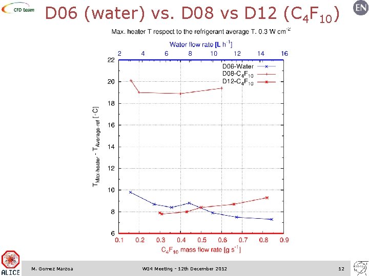
D 06 (water) vs. D 08 vs D 12 (C 4 F 10) M. Gomez Marzoa WG 4 Meeting - 12 th December 2012 12
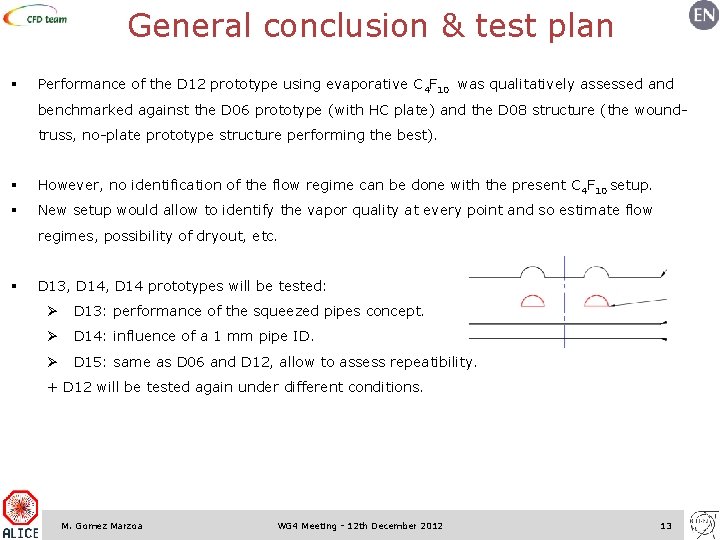
General conclusion & test plan § Performance of the D 12 prototype using evaporative C 4 F 10 was qualitatively assessed and benchmarked against the D 06 prototype (with HC plate) and the D 08 structure (the woundtruss, no-plate prototype structure performing the best). § However, no identification of the flow regime can be done with the present C 4 F 10 setup. § New setup would allow to identify the vapor quality at every point and so estimate flow regimes, possibility of dryout, etc. § D 13, D 14 prototypes will be tested: Ø D 13: performance of the squeezed pipes concept. Ø D 14: influence of a 1 mm pipe ID. Ø D 15: same as D 06 and D 12, allow to assess repeatibility. + D 12 will be tested again under different conditions. M. Gomez Marzoa WG 4 Meeting - 12 th December 2012 13
Update on stave thermal testing Claudio BORTOLIN Enrico DA RIVA Corrado GARGIULO Manuel GOMEZ MARZOA WG 4 Meeting - 12 th December 2012 M. Gomez Marzoa WG 4 Meeting - 12 th December 2012 14
Backup M. Gomez Marzoa WG 4 Meeting - 12 th December 2012 15
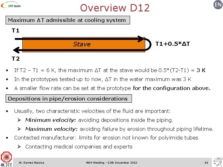
Overview D 12 Maximum ΔT admissible at cooling system T 1 Stave T 1+0. 5*ΔT T 2 § If T 2 – T 1 = 6 K, the maximum ΔT at the stave would be 0. 5*(T 2 -T 1) = 3 K § In the prototypes tested up to now, ΔT in the water maximum was 3 K § A smaller flow rate can be set at the prototype for the configuration above. Depositions in pipe/erosion considerations § Usually, two characteristic velocities of the fluid are important: Ø Minimum velocity: avoiding depositions inside the piping. Ø Maximum velocity: avoiding failure by erosion throughout piping lifetime. § Contacted manufacturer: limits for erosion not known for polyimide tubes Ø Contacting medical companies and experts M. Gomez Marzoa WG 4 Meeting - 12 th December 2012 16
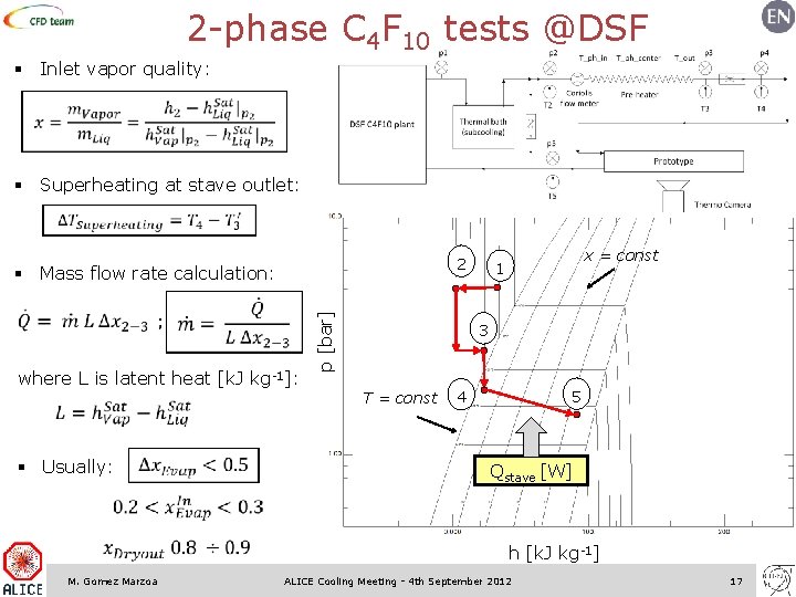
2 -phase C 4 F 10 tests @DSF § Inlet vapor quality: § Superheating at stave outlet: 2 where L is latent heat [k. J kg-1]: § Usually: p [bar] § Mass flow rate calculation: x = const 1 3 T = const 5 4 Qstave [W] M. Gomez Marzoa h [k. J kg-1] ALICE Cooling Meeting - 4 th September 2012 17
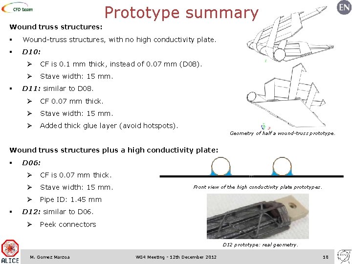
Prototype summary Wound truss structures: § Wound-truss structures, with no high conductivity plate. § D 10: § Ø CF is 0. 1 mm thick, instead of 0. 07 mm (D 08). Ø Stave width: 15 mm. D 11: similar to D 08. Ø CF 0. 07 mm thick. Ø Stave width: 15 mm. Ø Added thick glue layer (avoid hotspots). Geometry of half a wound-truss prototype. Wound truss structures plus a high conductivity plate: § § D 06: Ø CF is 0. 07 mm thick. Ø Stave width: 15 mm. Ø Pipe ID: 1. 45 mm Front view of the high conductivity plate prototypes. D 12: similar to D 06. Ø Peek connectors D 12 prototype: real geometry. M. Gomez Marzoa WG 4 Meeting - 12 th December 2012 18
- Slides: 18