Update of layout of electron beam line and

Update of layout of electron beam line and vapour source L. Verra, R. Ramjiawan AWAKE Run 2 Meeting, CERN Thursday 26 th March 2020
 had a meeting")
Overview • We (P. Muggli, L. Verra, F. Velotti, R. Ramjiawan) had a meeting to discuss how best to approach studying the layout of the electron line particularly with regards to the vacuum window placement. • It would be good to have a cohesive approach for this, plans for these studies are outlined in this presentation.
 membrane positioned further upstream. Great simplification of the design of the gap area")
1) membrane positioned further upstream. Great simplification of the design of the gap area Si. N membrane vacuum e- be a m Rb vapor B p+ beam laser beam SM’or x laser beam LBDP ~m ACC’or
 membrane positioned further upstream. If the foil is positioned where an imaging waist")
1) membrane positioned further upstream. If the foil is positioned where an imaging waist is, the emittance growth is negligible. e. g. for a 1: 1 imaging, β = 5. 1 mm (matched beam for npe = 7 E 14 cm-3) εN_in [mm mrad] σw [μm] ΔεN Δβ 2 5. 6 <1/1000 5 8. 9 “ “ 10 13 “ “ 15 15 “ “ 20 18 “ “ Easier or more difficult to transport with a 1: 1 imaging? (The increase on emittance and decrease on beta is below 1% up to 10: 1 imaging)

Current beamline design • The current beamline design does not have one singular imaging waist for both x and y together and so I will look into this next. • I will study designs with e. g. 2: 1, 3: 1, 4: 1 etc. imaging.

1: 1 imaging •
 model of")
Modelling the window within beamline design • Have added a simple (MCS) model of the foil/vacuum window into the beamline model, so we can study the beamline + window using (PTC) tracking. Possible vacuum window placement • We can then look at different positions/widths of the vacuum window with full tracking of non-linear effects, and can optimise the beamline with the foil already included. Rebecca Ramjiawan
 vacuum window right before injection Vacuum window + movable laser beam dump to")
2) vacuum window right before injection Vacuum window + movable laser beam dump to protect the window injection point e. B p+ • very difficult to engineer • more invasive on beam optics x hv

Upper limit: waist is downstream the foil Lower limit: βout < βin βout = 9. 5 mm for npe = 2 E 14 cm-3 ε 0 = 20 mm mrad εin = 2 mm mrad βout = 5. 1 mm for npe = 7 E 14 cm-3 εout= 11 mm mrad εin = 2 mm mrad

Also the waist position is affected: it moves upstream βout = 9. 5 mm for npe = 2 E 14 cm-3 βin = 5. 1 mm for npe = 7 E 14 cm-3 εout = 20 mm mrad εin = 2 mm mrad εout = 11 mm mrad εin = 2 mm mrad

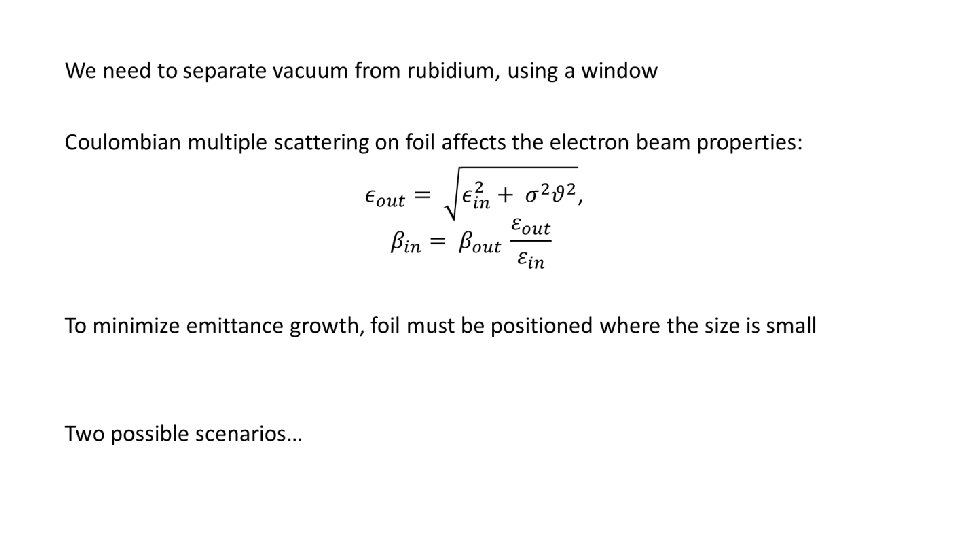
Conclusions: We have two possible solutions to solve one part of the injection puzzle: 1. The membrane is positioned upstream where an imaging waist is (need to adjust the beamline design accordingly) 2. We use two foils right before the injection: once we fix thickness and material, we can univocally determine the necessary incoming parameters
- Slides: 13