
University of Tampere CS Department Jyrki Nummenmaa SOFTWARE
- Slides: 40
University of Tampere, CS Department Jyrki Nummenmaa SOFTWARE ARCHITECTURES An architecture contains the information on how the software devides into building blocks. Software Engineering – http: //www. cs. uta. fi/se
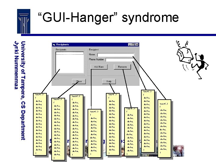
“GUI-Hanger” syndrome University of Tampere, CS Department Jyrki Nummenmaa Func. X(…) { do this; do that; do this; do that; do this; do that; do this; do that; } Func. X(…) { do this; do that; do this; do that; do this; do that; do this; do that; do this; do that; do this; do that; } Func. X(…) { do this; do that; do this; do that; do this; do that; } Software Engineering – http: //www. cs. uta. fi/se
Why software architectures? University of Tampere, CS Department Jyrki Nummenmaa • Managing complexity – It is easier to manage complexity, if we divide the application into reasonable parts. • Maintainability – Usually a reasonable architecture makes it much easier to maintain the software. – This may actually be the biggest reason for architectural design. • Efficiency – A good architecture enables us to isolate the potential causes for inefficiency and makes it possible to scale up performance when load increases. Software Engineering – http: //www. cs. uta. fi/se
Architectural Design Choices University of Tampere, CS Department Jyrki Nummenmaa Choices Made In Architectural Design: • Components • High-Level Design Patterns • Architectural Styles • A Possible Framework Architecture • Processes and Hardware • Processes and Communication • Other Architecture-Related Decisions • -> Some of these issues depend on each other strongly. • Let’s have a look at some historical development. Software Engineering – http: //www. cs. uta. fi/se
Monolithic Architecture / 1 University of Tampere, CS Department Jyrki Nummenmaa • Monolithic systems are not divided into independent parts. They typically run on a single processing unit (computer). • There was a time when computers typically did not talk that much with each other. • This made monolithic systems more or less the only choice. • Lack of complicated communication speeds up processing, but it is hard to improve performance in any other way than increasing processing power for that one computer. Software Engineering – http: //www. cs. uta. fi/se
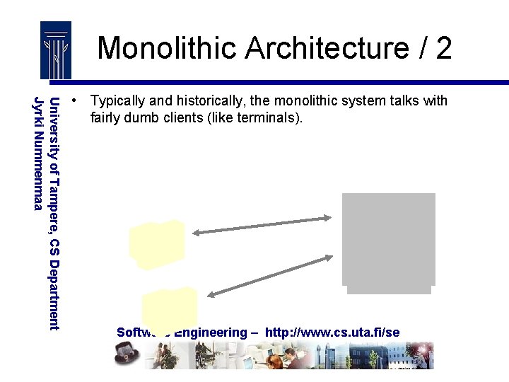
Monolithic Architecture / 2 University of Tampere, CS Department Jyrki Nummenmaa • Typically and historically, the monolithic system talks with fairly dumb clients (like terminals). Software Engineering – http: //www. cs. uta. fi/se
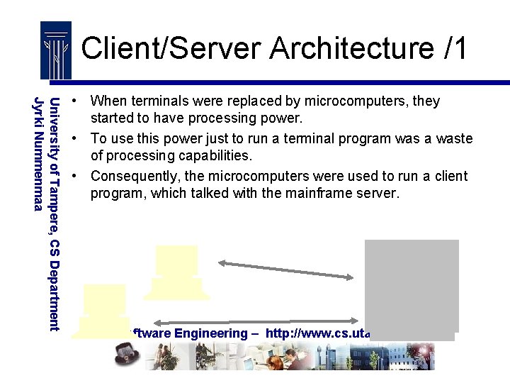
Client/Server Architecture /1 University of Tampere, CS Department Jyrki Nummenmaa • When terminals were replaced by microcomputers, they started to have processing power. • To use this power just to run a terminal program was a waste of processing capabilities. • Consequently, the microcomputers were used to run a client program, which talked with the mainframe server. Software Engineering – http: //www. cs. uta. fi/se
Client/Server Architecture /2 University of Tampere, CS Department Jyrki Nummenmaa • Fat clients contained more functionalities and data. • Thin clients contained more or less terminal-type functionalities. • Client/Server (C/S) computing was the first step towards multi -tier (multi-layer) architectures on processing unit level. • It allowed a better division of work. • However, fat clients also needed maintenance and installations to keep up with current versions. Software Engineering – http: //www. cs. uta. fi/se
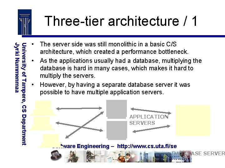
Three-tier architecture / 1 University of Tampere, CS Department Jyrki Nummenmaa • The server side was still monolithic in a basic C/S architecture, which created a performance bottleneck. • As the applications usually had a database, multiplying the database is hard in many cases, which makes it hard to multiply the servers. • However, by having a separate database server it was possible to have multiple application servers. APPLICATION SERVERS Software Engineering – http: //www. cs. uta. fi/se DATABASE SERVER
Three-tier architecture / 2 University of Tampere, CS Department Jyrki Nummenmaa • The database server only runs the database, as having several of them is difficult. • If there are database server performance problems, get a more powerful server! • You may use several servers for backup to always have a backup server on-line ready for action. • The three-tier architecture is fairly common. • To make client installation easier, it is possible to have a client server (or UI server), from which the client is software is loaded for execution (like an applet to be executed in the browser). Software Engineering – http: //www. cs. uta. fi/se
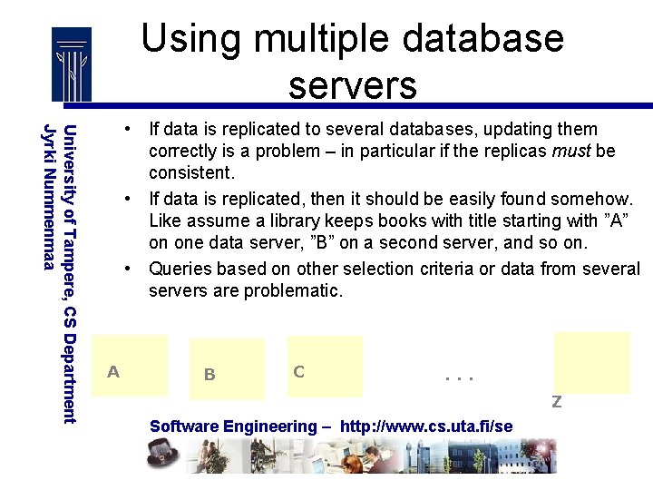
Using multiple database servers University of Tampere, CS Department Jyrki Nummenmaa • If data is replicated to several databases, updating them correctly is a problem – in particular if the replicas must be consistent. • If data is replicated, then it should be easily found somehow. Like assume a library keeps books with title starting with ”A” on one data server, ”B” on a second server, and so on. • Queries based on other selection criteria or data from several servers are problematic. A B C . . . Z Software Engineering – http: //www. cs. uta. fi/se
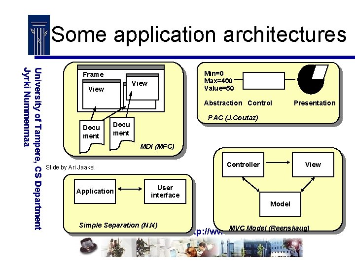
Some application architectures University of Tampere, CS Department Jyrki Nummenmaa Min=0 Max=400 Value=50 Frame View Abstraction Control Docu ment Presentation PAC (J. Coutaz) Docu ment MDI (MFC) Controller Slide by Ari Jaaksi. Application View User interface Model Simple Separation (N. N) MVC Model (Reenskaug) Software Engineering – http: //www. cs. uta. fi/se
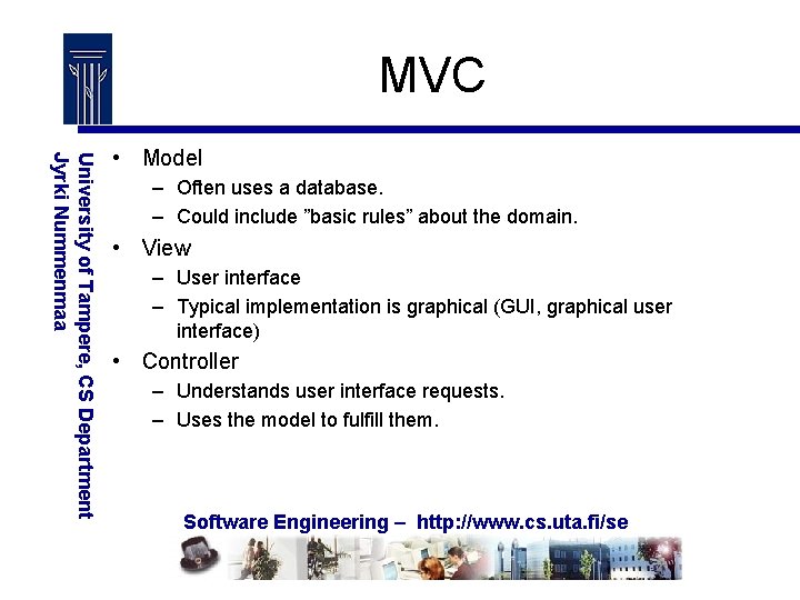
MVC University of Tampere, CS Department Jyrki Nummenmaa • Model – Often uses a database. – Could include ”basic rules” about the domain. • View – User interface – Typical implementation is graphical (GUI, graphical user interface) • Controller – Understands user interface requests. – Uses the model to fulfill them. Software Engineering – http: //www. cs. uta. fi/se
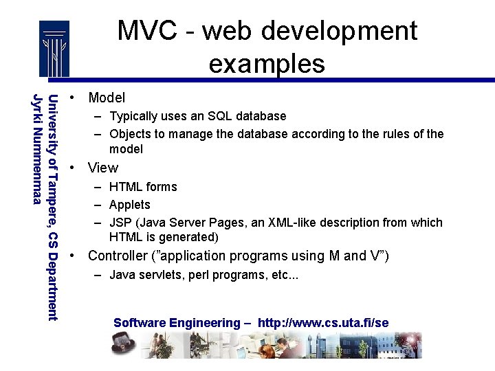
MVC - web development examples University of Tampere, CS Department Jyrki Nummenmaa • Model – Typically uses an SQL database – Objects to manage the database according to the rules of the model • View – HTML forms – Applets – JSP (Java Server Pages, an XML-like description from which HTML is generated) • Controller (”application programs using M and V”) – Java servlets, perl programs, etc. . . Software Engineering – http: //www. cs. uta. fi/se
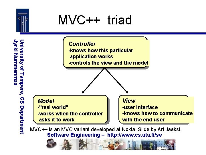
MVC++ triad University of Tampere, CS Department Jyrki Nummenmaa Controller -knows how this particular application works -controls the view and the model Model View -"real world" -works when the controller asks it to work -user interface -knows how to communicate with the end user MVC++ is an MVC variant developed at Nokia. Slide by Ari Jaaksi. Software Engineering – http: //www. cs. uta. fi/se
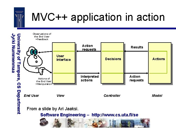
MVC++ application in action University of Tampere, CS Department Jyrki Nummenmaa Observations of the End User =Feedback Action requests User Interface Decisions Interpreted actions Actions of the End User =Manipulation End User Results View Actions Action requests Controller From a slide by Ari Jaaksi. Software Engineering – http: //www. cs. uta. fi/se Model
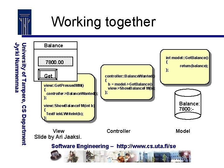
Working together University of Tampere, CS Department Jyrki Nummenmaa Balance int model: : Get. Balance() { return(balance); }; 7800. 00 Get view: : Get. Pressed. MM() { controller->Balance. Wanted(); }; controller: : Balance. Wanted() { b = model->Get. Balance(); view->Show. Balance. FM(b); }; Balance: 7800: - view: : Show. Balance. FM(int b) { Text. Field. Write. Int(b); }; View Slide by Ari Jaaksi. Controller Model Software Engineering – http: //www. cs. uta. fi/se
Peer-To-Peer Computing University of Tampere, CS Department Jyrki Nummenmaa • The above processing architectures have assumed that we have separate servers and clients and the configuration of the system is controlled in a centralised fashion. • In Peer-To-Peer computing, each computer (node) is equal, and the nodes may ask each other for processing services. • The nodes may contact each other flexibly and forward processing requests, which removes a fixed configuration for processing. • Grid computing (”a software infrastructure enabling flexible, secure and coordinated resource sharing”) Software Engineering – http: //www. cs. uta. fi/se
Processing Unit vs. Software Architecture University of Tampere, CS Department Jyrki Nummenmaa • If an architecture divides processing into different types of processing units (clients and various servers), then of course this division implies also a division of the software functionalities. • However, there is also architectural structural decisions, which do not need to be based on the processing unit architecture. Software Engineering – http: //www. cs. uta. fi/se
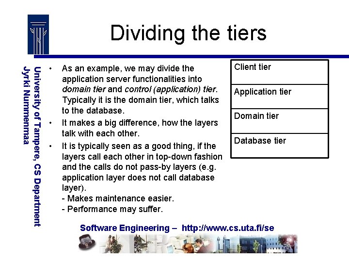
Dividing the tiers University of Tampere, CS Department Jyrki Nummenmaa • • • As an example, we may divide the application server functionalities into domain tier and control (application) tier. Typically it is the domain tier, which talks to the database. It makes a big difference, how the layers talk with each other. It is typically seen as a good thing, if the layers call each other in top-down fashion and the calls do not pass-by layers (e. g. application layer does not call database layer). - Makes maintenance easier. - Performance may suffer. Client tier Application tier Domain tier Database tier Software Engineering – http: //www. cs. uta. fi/se
Issues with multi-layer architectures University of Tampere, CS Department Jyrki Nummenmaa • Number of layers • Error/exception management (what to pass on, what to process) • Callback from lower layers. • Interfaces between layers / encapsulation of layers. • Maintenance knock-on effects (do changes of one layer imply changes in other layers? ) Software Engineering – http: //www. cs. uta. fi/se
Components - What? University of Tampere, CS Department Jyrki Nummenmaa • Component technologies can be seen as packaging technologies • Independent • Can be used as a building block to build larger systems – dynamic, ”plug & play” linking • Have a well-defined interface, which hides the implementation completely • Can be treated as a product of its own • Can be installed separately • Can be implemented with any language, as long as it implements the necessary interfaces Software Engineering – http: //www. cs. uta. fi/se
Components - Why? University of Tampere, CS Department Jyrki Nummenmaa • Object-oriented source-level re-use of code requires same source code language. • Object-oriented source-level re-use may require understanding of the implementation. • Building the system from source-level pieces requires that these pieces compile happily with each other. • We want to avoid the above problems and build binary components with well-defined interfaces. Software Engineering – http: //www. cs. uta. fi/se
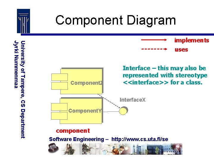
Component Diagram University of Tampere, CS Department Jyrki Nummenmaa implements uses Component. Z Interface – this may also be represented with stereotype <<interface>> for a class. Interface. X Component. Y component Software Engineering – http: //www. cs. uta. fi/se
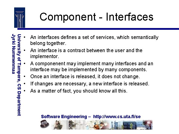
Component - Interfaces University of Tampere, CS Department Jyrki Nummenmaa • An interfaces defines a set of services, which semantically belong together. • An interface is a contract between the user and the implementor. • A componenent may implement many interfaces and an interface may be implemented by many components. • Once an interface is released, it does not change. • If changes are necessary, a new interface is released. • As a matter of fact, you should know all this. Software Engineering – http: //www. cs. uta. fi/se
Component Technologies University of Tampere, CS Department Jyrki Nummenmaa • Microsoft COM & DCOM (distributed COM) • CORBA standard – several vendors – heavyweight system • Java Beans Software Engineering – http: //www. cs. uta. fi/se
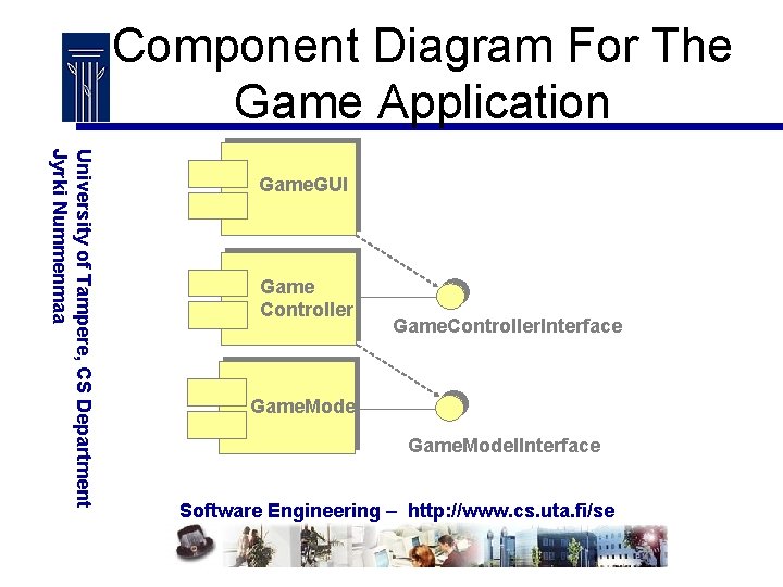
Component Diagram For The Game Application University of Tampere, CS Department Jyrki Nummenmaa Game. GUI Game Controller Game. Controller. Interface Game. Model. Interface Software Engineering – http: //www. cs. uta. fi/se
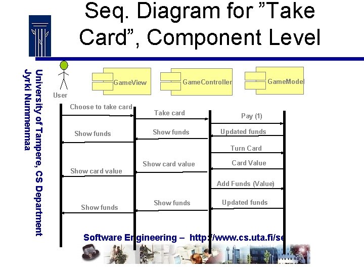
Seq. Diagram for ”Take Card”, Component Level University of Tampere, CS Department Jyrki Nummenmaa Game. View Game. Model Game. Controller User Choose to take card Show funds Take card Show funds Pay (1) Updated funds Turn Card Show card value Card Value Add Funds (Value) Show funds Updated funds Software Engineering – http: //www. cs. uta. fi/se
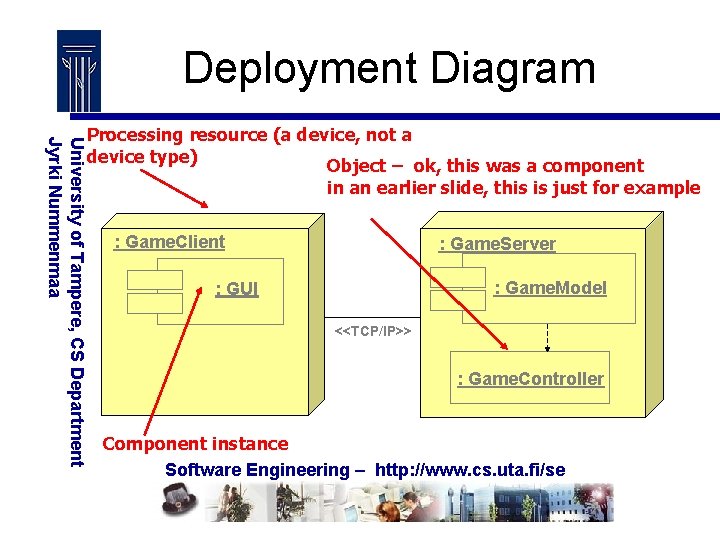
Deployment Diagram University of Tampere, CS Department Jyrki Nummenmaa Processing resource (a device, not a device type) Object – ok, this was a component in an earlier slide, this is just for example : Game. Client : Game. Server : Game. Model : GUI <<TCP/IP>> : Game. Controller Component instance Software Engineering – http: //www. cs. uta. fi/se
FRAMEWORKS University of Tampere, CS Department Jyrki Nummenmaa • A an application framework contains core parts for an application. • The framework serves as a starting-point for application development. • We add new things to the core. • In case of OO software development, a framework may contain a set of core classes. • Naturally, the new system inherits the basic architecture from the framework. Software Engineering – http: //www. cs. uta. fi/se
Black-box vs. white-box frameworks University of Tampere, CS Department Jyrki Nummenmaa • In black-box frameworks, we just build things on top of the framework without a need to see the implementation details in the framework. - Easy to use • In white-box frameworks, we typically implement new subclasses based on the classes in the framework. - More flexible Software Engineering – http: //www. cs. uta. fi/se
Frameworks vs. components University of Tampere, CS Department Jyrki Nummenmaa • When you use components, you typically write the “main programs” yourself and call the services from the components. • When you use frameworks, the framework includes the “main programs” and you implement the application-specific special services, which the framework calls. - The so-called Hollywood principle: “Don’t call us, we call you”. Software Engineering – http: //www. cs. uta. fi/se
Frameworks – conclusions University of Tampere, CS Department Jyrki Nummenmaa • It is harder to write a good application framework than it is to write a good application. • However, if it succeeds, a lot of effort can be saved in producing future applications based on the framework. • In particular, it is possible to get the products out earlier (a time-to-market improvement). Software Engineering – http: //www. cs. uta. fi/se
Design Patterns University of Tampere, CS Department Jyrki Nummenmaa • The idea is to copy an existing design idea and modify it to our needs. • The idea of copying designs like this is the basic idea behind design patterns. • It has been difficult to reuse code. The idea of design patterns is to reuse ideas. • In a way, applying the MVC model is reusing the idea. However, there have been efforts to give a fixed format for presenting design patterns. • Design patterns can be used at architectural design as well as in more detailed design. Software Engineering – http: //www. cs. uta. fi/se
Design Pattern Description University of Tampere, CS Department Jyrki Nummenmaa • Name • Problem • Solution – Static: E. g. Class Diagram – Dynamic: E. g. Sequence Diagram • Strategy – How to implement the pattern • Consequences – Results and trade-offs Software Engineering – http: //www. cs. uta. fi/se
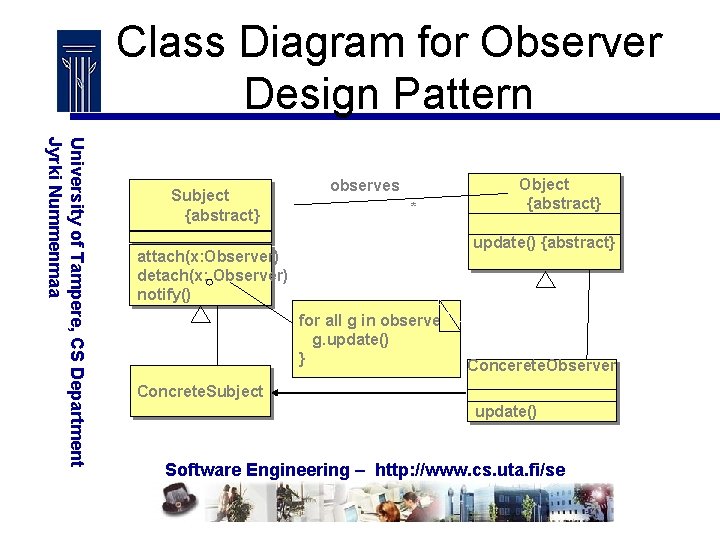
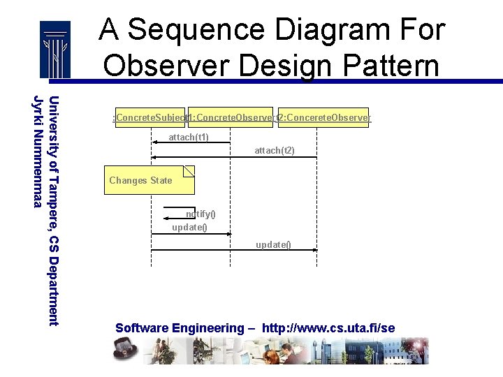
Design Pattern ”Observer” University of Tampere, CS Department Jyrki Nummenmaa • Problem: We want to keep a number of objects (observers) aware of the state of an object (subject) • This is done by making the observers subscribe to the subject. • Whenever the subjects state changes, it will publish information about that to all subscribed observers. Software Engineering – http: //www. cs. uta. fi/se
Class Diagram for Observer Design Pattern University of Tampere, CS Department Jyrki Nummenmaa Subject {abstract} attach(x: Observer) detach(x: Observer) notify() observes * Object {abstract} update() {abstract} for all g in observes { registers g. update() } Concerete. Observer Concrete. Subject update() Software Engineering – http: //www. cs. uta. fi/se
A Sequence Diagram For Observer Design Pattern University of Tampere, CS Department Jyrki Nummenmaa : Concrete. Subjectt 1: Concrete. Observert 2: Concerete. Observer attach(t 1) attach(t 2) Changes State notify() update() Software Engineering – http: //www. cs. uta. fi/se
Some observations University of Tampere, CS Department Jyrki Nummenmaa • A subject and the respective observers need minimal information on each other. • In fact, they need to implement the required operations (attach, detach, notify, update), but that’s about that. • This way, we get a high level of independence in their implementations. Software Engineering – http: //www. cs. uta. fi/se
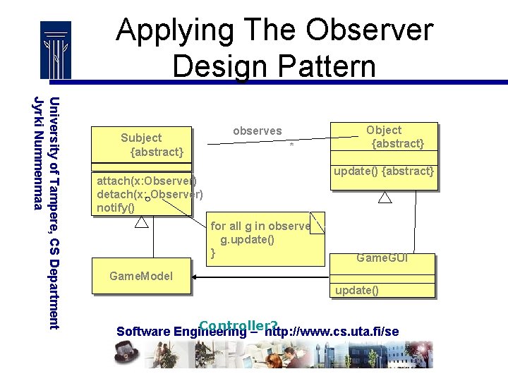
Applying The Observer Design Pattern University of Tampere, CS Department Jyrki Nummenmaa Subject {abstract} observes * Object {abstract} update() {abstract} attach(x: Observer) detach(x: Observer) notify() for all g in observes { registers g. update() } Game. GUI Game. Model update() Controller? Software Engineering – http: //www. cs. uta. fi/se