UNIVERSAL JOINTS Chapter Objectives Understand describe the purpose

UNIVERSAL JOINTS

Chapter Objectives �Understand describe the purpose and construction of common RWD drive shaft designs. �Understand describe the purposes and construction of common Universal joint designs. �Explain the importance of drive shaft balance. �Explain the natural speed variations inherent to a drive shaft. �Describe the effects of canceling Universal joint angles.

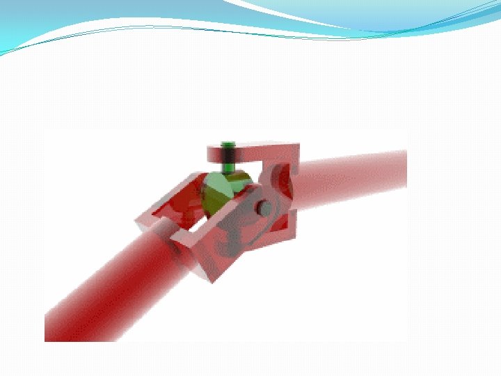
Definition Universal joint: - is a connection between two intersecting rotating shafts which are coplanar and are inclined at an angle, with respect to each other. It is also a positive, mechanical connection between two. . . ……. . rotating shafts A and B. And is used to transmit both motion and power from shaft A to shaft B. Shaft B Shaft A U-joint

Applications of U-joints have many applications in: - aircraft, Control mechanisms, electronics, instrumentation, textile machinery tool drives etc. Uses of U-joint Ø to carry maximum load-capacity for a given size. Øuniversal joints with thermoplastic body members are used in light industrial applications by their Selflubricating feature, light weight, corrosion resistance and capability for high-speed operation are significant advantages. ØDisadvantage: - its expensiveness… (From http: //en. wikipedia. org/wiki/Universal_joint

Universal Joints �Are sometimes referred to as Cardan Joints, Spicer Joins , or Hooke joints �Allow for angle changes between the drive shaft, the transmission output shaft, and the rear axle housing

Universal Joint Characteristics �Speed variations �While operating at an angle, U-joints speed up and slow down twice per revolution �Joint phasing �The vibrations caused by one U-joint are transmitted to the other one
 �Canceling angles �The angle of the front U-joint is offset")
Universal Joint Characteristics (cont’d) �Canceling angles �The angle of the front U-joint is offset by the rear one �The correct angle must be maintained to minimize vibration

Universal Joint Designs �Single universal joint �Sometimes known as single Cardan/Spicer Universal joint �Consists of a cross and four needle bearings �Double Cardan joint �Consists of two single U-joints joined by a center yoke and a ball and socket
 �Slip joint �Allows for changes in driveshaft length caused by")
Universal Joint Designs (cont’d) �Slip joint �Allows for changes in driveshaft length caused by suspension travel �Components include: � Transmission � The output shaft slip joint � A yoke and U-joint � The driveshaft

Universal Joint �Allows non-parallel shafts to be coupled. �Considered to be a variation of a solid coupling. �Generally, requires lubrication. 11

Industrial applications operate continuously and with high torque loads. This demands maximum strength and long life of the universal joint components. The modern universal joint has become much more complex than its simple ancestor. The universal joints manufactured by Ameridrives are made for demanding industrial applications. Universal joints have several unique features that make them ideal for a variety of applications. Most significant is the ability of the universal joint to operate at high misalignment angles. Operating angles up to 25 degrees are not uncommon. Another feature of the universal joint is the bearing and seal design that resists lubrication loss and contamination. This makes Ameridrives Universal Joints suitable for applications where severe atmospheric conditions would put other couplings at a distinct disadvantage. When compared to other high misalignment couplings, universal joints operate with negligible backlash or radial clearance. The difference can be significant on applications where backlash is critical. Ameridrives Universal Joint yokes are precisely engineered using the latest design technologies. They are manufactured as a onepiece, closed bearing eye design, assuring the highest degree of strength and minimum distortion under load. 12

Industrial applications operate continuously and with high torque loads. This demands maximum strength and long life of the universal joint components. The modern universal joint has become much more complex than its simple ancestor. The universal joints manufactured by Ameridrives are made for demanding industrial applications. Universal joints have several unique features that make them ideal for a variety of applications. Most significant is the ability of the universal joint to operate at high misalignment angles. Operating angles up to 25 degrees are not uncommon. Another feature of the universal joint is the bearing and seal design that resists lubrication loss and contamination. This makes Ameridrives Universal Joints suitable for applications where severe atmospheric conditions would put other couplings at a distinct disadvantage. When compared to other high misalignment couplings, universal joints operate with negligible backlash or radial clearance. The difference can be significant on applications where backlash is critical. Ameridrives Universal Joint yokes are precisely engineered using the latest design technologies. They are manufactured as a onepiece, closed bearing eye design, assuring the highest degree of strength and minimum distortion under load. 13

The universal joint can be used as a single joint or it can be used in pairs. When used as a single joint, only angular misalignment is accommodated. Since nearly every installation requires the coupling to also accommodate offset misalignment, universal joints should be used in pairs. Using universal joints in pairs also corrects for non-uniform angular velocity caused by the rotational characteristics of a single joint. 14

15

U-joint 16

17

Amerigear® Spindles Americardan™ U-Joints VL Mill Spindles 18

Ameridrives U 3600 FT Universal Joints on a large section mill 19

20

21

22

VELOCITY RATIO OF SHAFTS Consider the two shafts A and B which are the driver and follower respectively. The axes of the two shafts are inclined at angle from the plan view of the designer. When the shafts A and B rotate A-A traces a circle(shown by b-b) while B-B traces an ellipse(shown by a-a). A schematic representation of a universal joint From Alem Bazezew Text book series

In reality Follower . Driver Universal joint From http: //www. ehow. com/info_8181311_types-ujoints. html Driver Follower Universal joint From http: //en. wikipedia. org/wiki/Universal_joint.

When the two shafts are cross sectioned A B . Follower A B Driver A B B A

If shaft A turns through an angle from AA to A 1 A 1 , then the projection of BB will also turn through angle to B 1 B 1. During this time the angle turned by shaft B is as observed from the axis of shaft B. The projections of B 1 and B 2 on AA are C 1 and C 2. B 1 O Note: and shows the fluctuation of shaft B o C 1 B B 2 O O C 1 B 1 C 1 B 1=C 2 B 2 OC 2=OB 1 Plan and elevation of a cross-shaped universal joint From Alem Bazezew Text book series C 2

. . sec

P 2 P 1 P 3 P 4 . . Polar angular velocity diagram From Alem Bazezew Text book series Conclusion: 1) At P 1, P 2, P 3, P 4 Þ A = B. 2) B/n (P 1 up to P 2) &. . (P 3 up to P 4) => A > B. 3) B/n (P 1 up to P 4) &. . (P 2 up to P 3)

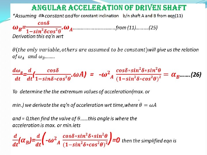

Thus, having obtained the angular position for which the angular acceleration is maximum, the angular acceleration is obtained by substituting for in the equation of the acceleration.

DOUBLE HOOK’S JOINT usingle Hooke’s joint in automobile would vary the speed of either car or engine during each revolution of the driver shaft. -*this occurs high stresses on shaft and slippage on the tires. -*so the best solution for this is to use double Hooke’s joint. -*it provides uniformity of speed b/n input and output ends by limiting the variation of speed to the intermediate shaft. -*If the driver and follower shafts are inclined equally relative to the intermediate shaft the fluctuation of speed is confined to the intermediate Shaft alone. To reduce the inertia due to fluctuation in transmission, the intermediate shaft can be made short and light.

Double universal joint From Alem Bazezew Text book series Double Hooke’s joint From http: //en. wikipedia. org/wiki/Universal_joint


1 Jun 4 /2 013 THANK YOU !!! From Group
- Slides: 35