UnitIV Induction Motor Stator Design 1 Application Why
 2. Working")
 Stator φ D Rotor")

 Total No. of conductors, Z= No. of phases")
 v Large no. of turns")


- Slides: 12
Unit-IV Induction Motor Stator Design 1. Application (Why it is used? ) 2. Working Principle (How does the rotor of IM rotates? ) 3. Types A. Squirrel Cage B. Slip Ring Difference a. Construction b. Performance
Choice of specific magnetic loading or average flux density (Bav) Stator φ D Rotor Where, D is diameter at air gap or inner diameter of stator φ is flux per pole P is total number of poles L is stator core length L
Vs Ir’ Is 2 Is 1 φs 2 φs 1 Im 1 Ir Im 2 φ
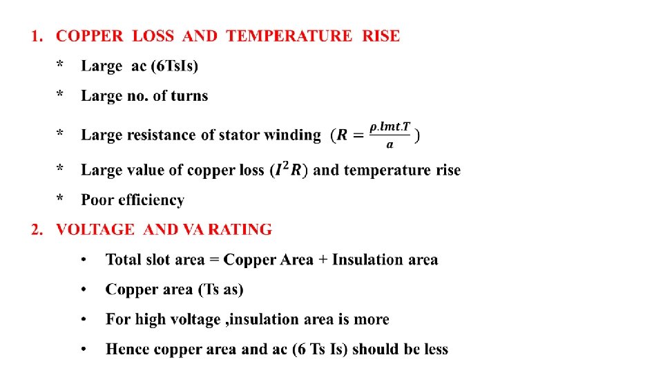
Choice of specific electric loading (ac) Total No. of conductors, Z= No. of phases (3) x 2 conductors/turn x Turns per phase, TS
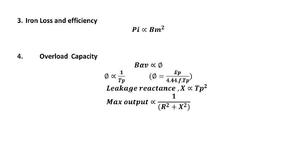
3. OVERLOAD CAPACITY v Large ac (6 Ts. Is) v Large no. of turns v Large value of leakage reactance X v Small value of overload capacity
Factors affecting selection of type of Stator slot Two types of slots are used in Induction motor Semi enclosed slot Open Slot Teeth 1. Coils are formed and insulated outside and then inserted in slot. 2. Gap contraction factor is large. 3. Magnetizing current is large. 4. Leakage reactance is less. 5. Variation in reluctance is more and hence tooth pulsation loss and noise is more Slot 1. 2. 3. 4. 5. Teeth Coils are formed and insulated in slot. Gap contraction factor is small. Magnetizing current is small. Leakage reactance is more. Variation in reluctance is less and hence tooth pulsation loss and noise is less
Factors affecting choice of number of slots 1. Leakage reactance: For large number of slot , width of insulation is more. Hence leakage reactance is less and overload capacity is more. 2. Ventilation: For large number of slots, width of slot and hence width of teeth is less Hence teeth becomes mechanically weak and supported by ventilating duct, Which obstructs ventilation. 3. Magnetizing current and Iron Loss: For large number of slots, area of teeth becomes less Hence flux density increases, which increases magnetizing current and Iron loss
4. Cost: For large number of slots, large number of coils to be formed and Insulate, which increases cost of winding 5. Tooth pulsation loss and noise: Large number of slots produces minimum variation in reluctance , hence tooth pulsation loss and noise is less.
Choice of length of air gap 1. Power Factor If the length of air gap increases, then induction motor draws more magnetizing current Vs Is 2 Is 1 Ir’ φs 2 φs 1 Im 1 Ir Im 2 φ
2. Overload Capacity With increase in the length of air gap, zig-zag leakage flux decreases with less leakage reactance, overload capacity increases. Slot Teeth