UNITIII SHEARBONDTORSION TORSI ON SHEAR Module 1 Behaviour

UNIT-III SHEAR-BOND-TORSION

TORSI ON SHEAR Module 1: Behaviour of RC Beams in Shear and Torsion: Modes of Cracking , Shear Transfer Mechanisms , Shear Failure Modes, Critical Sections for Shear Design , Influence of Axial Force on Design Shear Strength, Shear Resistance of Web Reinforcement, Compression Field Theory, Strut-and - Tie Model. Equilibrium Torsion and Compatibility Torsion, Design
 stress fx and")
1. Flexural and shear stresses in prismatic beams v Flexural (normal) stress fx and the Shear stress at any point in the section, located at a distance y from the neutral axis, are given by: I = second moment of area of the section about the neutral axis Q = first moment of area about the neutral axis of the portion of the section above the layer at distance y from the NA b = width of the beam at the layer at which is calculated. v variation of shear stress is parabolic, with a maximum value at the neutral axis and zero values at the top and bottom of the section.

v Combined flexural and shear stresses can be resolved into equivalent principal stresses planes, inclined at an angle f 1 and f 2 acting on orthogonal to the beam axis Principal stresses

v for elements located at the neutral axis – Condition of Pure Shear exists , τ is maximum and fx = 0 , f 1 = f 2 = τmax and α = 45 o v Principal stress trajectories’ are a set of orthogonal curves whose tangent/normal at any point indicate the directions of the principal. stresses at that point Principal Tensile Stress (PTS) Trajectory Principal Compressive Stress Trajectory takes the form of an arch while that of tensile stresses have the curve of a catenary or like a suspended chain. Towards midspan where shear stresses Principal stress trajectories are low and bending dominant the direction of principal stresses tend to be parallel to the beam axis. Potential crack pattern Near the supports where the shearing forces are greater, the principal stresses Cracks would develop in a direction that become inclined and greater the shear is perpendicular to that of the principal force greater tensile stress. is the inclination.

2. Modes of Cracking in RC Beams Two types of inclined cracking occur in concrete beams v Web Shear Cracking v Flexure – Shear Cracking v Web Shear cracking starts from near NA location when the PTS due to shear exceed the tensile strength of concrete. Usually occur in I beams (thin webs) v Flexure – Shear cracking is an extension of vertical flexural cracking and develops when the PTS due to combined shear and flexural tensile stresses

3. Shear failure modes in beams without web rebars Case 1: a/d < 1 DEEP BEAMS a v Without web reinforcement, inclined cracking transforms the beam into a tied -arch with tension element as longitudinal rebars and compression element as cracked concrete v The tension element may fail by yielding, fracture or failure of anchorage. v OR compression chord may fail by crushing of concrete

Case 2: 1 < a/d < 2. 5 Failure is initiated by an inclined crack � usually a flexure-shear crack. The actual a failure may take place either by (1) crushing of the reduced concrete section above the tip of the crack under combined compression, shear termed and a shear- compression failure (2)or secondary cracking along the Such failures usually occurtermed beforeshear the failure due to moment resisting tension reinforcement, capacity of failure. beam is exhausted -tension

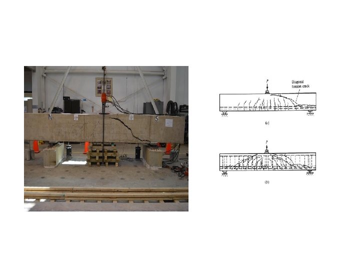
Case 3: 2. 5 < a/d < 6 v Such beams may fail either in shear or in flexure. Flexural tension cracks develop early. Failure in shear occurs by the propagation of inclined flexuralshear cracks. v If shear reinforcement is not provided, the cracks extend rapidly to the top of the a beam; the failure occurs suddenly and is termed diagonal tension failure. Addition of web reinforcement enhances the shear v strength Loads canconsiderably. be carried until failure occurs in a shear-tension mode (yielding of the shear reinforcement) or in a shear-compression mode (If shear reinforcement is excessive, it may not yield; instead concrete in diagonal compression gets crushed), or in a flexural mode. v The limiting a/d ratio above which flexural failure is certain depends on the

Note: Web−Crushing Failure I−beams with web reinforcement may fail by the crushing of concrete in the web portion between the inclined cracks under diagonal compression forces

4. Shear Transfer Mechanisms Shear resistance in reinforced concrete beams is provided by the shear transfer in the compression zone, aggregate interlock across crack face, stirrups crossing the shear crack, and dowel action of longitudinal reinforcing bars crossing the crack in cconcrete v Interface shear (aggregate interlock) force Va , transmitted along the inclined plane of the crack, resulting from the friction against relative slip between the interlocking surfaces of the crack. Its contribution can be
 V d V")
v Dowel force in the tension reinforcement (due to dowel action) V d V = Vc + Va + Vd + Vs = Vint v In the uncracked stage the applied shear is resisted almost entirely by concrete. V Vc v At the instance of flexural cracking, there is a redistribution of stresses, and some interface shear Va and dowel action Vd are induced v At the stage of diagonal tension cracking, the shear reinforcement that intercepts the crack contributes significantly to resist shear. All the four

V = Vc + Va + Vd + Vs = Vint Since methods to include Vay and Vd are not clearly available only two primary mechanisms are considered in practice. Vc is modified to take into account of Va and Vd V = Vc + Vs

5. Influence of Longitudinal Rebars content ; pt – 100 Ast / bd v The increase in pt in the flexural tension zone contributes to enhanced dowel action Vd , and control the propagation of flexural cracks. v This results in increase in the position of the neutral axis v The increased area of uncracked concrete in compression zone enhances contributions of Va and Vc v Thus the higher the percentage tension reinforcement, the greater the shear resistance in the concrete – up to a limit : Xu /d = Xu, max/d v This contribution is given in Table 19 of IS 456 which are computed from

v. For a concrete grade beyond a value of pt which corresponds to =1, c remains constant. v. This is the upper limit of contribution that can be expected from dowel action and control of crack propagation (increased depth of NA) v Detailing provisions as per CL 26. 2. 2 and 26. 2. 3 are satisfied in regions of rebar curtailment

6 Concept of Shear Span P P SHEAR SPAN The dimensionless ratio a/d or M / V d enables the prediction of failure modes of beam in flexural shear
(2/3) Average Shear Stress")
7. Concept of Nominal Shear Stress V/BD = (1. 5 V/BD)(2/3) Average Shear Stress A. Members with Uniform Depth The concept of average shear stress in a beam section is used in mechanics of materials is used in RC sections also t v = shear force / area of cross section = Vu / bd τ v is merely a parameter intended to aid design and to control shear stresses in RC members It does not actually represent the true average shear stress as C

B. Members with Varying Depth

Note on Computation of Nominal Shear Stress v When the depth increases in the same direction as the bending moment as in the case in cantilever beams, nominal shear stress is reduced. Use of the simpler equation for nominal shear stress gives conservative results. v Equation as per CL 40. 1. 1 is mandatory when the depth decreases with increasing moment. Compression face is sloping - tapered footings and cantilever beams v A similar correction is necessary and equations holds good in this case also. Use of the simpler equation for nominal shear stress gives
 Support")
8. Critical sections for shear computation Critical Section for Shear (22. 6. 2) Support Region When a support reaction introduces transverse compression in the end region of the member, the shear strength of this region is enhanced, and inclined cracks do not develop near the face of the support (which is usually the location of maximum shear). This is of particular significance in footing slabs where flexural (oneway) shear is a major design consideration

End Region subjected to transverse compression, inclined cracks do not develop in this region Support Region End Region subjected to transverse compression, inclined cracks do not develop in this region 450 Line of Dispersi on d Critical Section for Shear (22. 6. 2. 1) (Crack Initiation Plane) Support Region 450 Line of Dispersi on d > 2 d Critical Section for Shear (22. 6. 2. 1)

End Supporte d beam Beam Supporte d by columns Concentra ted Load within d from the face of support Member Loaded near the bottom (Inverted T beam) Critical section at d from the face of support Critical section at the face of support Beam Supported by girder of similar depth Beam Supported by monolithic vertical element (Suspende rs) Critical section at the face of support

9. Influence of Axial Force on Design Shear Strength v Axial force either compression or tension may act in conjunction with M and V due to reasons such as externally applied, prestressing and restraint forces due to shrinkage or temperature. v. Typical examples include ring beams in domes v Shear strength of concrete is generally improved in the presence of uniaxial compression and weakened in the presence of uniaxial tension. Effect of Axial Compression v The effect of an axial compressive force is to delay the formation of both v IS 456 specifies that the design flexural and inclined cracks, shear and also to decrease the angle of inclination α of the inclined cracks to the strength in the presence of axial longitudinal axis. compression should be taken as δ τc

Effect of Axial Tension v. Axial tensile force is expected to do exactly the reverse - it will decrease the shear strength, accelerate the process of cracking and increase the angle α of the inclined cracks. v No explicit provisions in IS 456 are available v. The following simplified expression for δ, based on the ACI Code may be used: When axial tension is also present, design for shear may be done based on the Compression Field Theory or the Strut-and-Tie Model,

10. Enhanced Shear Strength of Sections Close to Supports v Shear strength of concrete is enhanced in regions close to the support, when the support reaction introduces transverse compression. v Substantial portion of the load is transmitted to the support directly through strut action, rather than through flexural shear. d 300 d/tan 30 = 1. 732 d 2 d > 300
")
CL 40. 5. 1 Enhancement of Shear Strength in end region (40. 5. 1) > 300 < 2 d

EXAMPLE 1 B = 300 mm, d = 610 mm, D = 685 mm, fck = 25 MPa, P = 445 k. N at mid span, Ast = 2458 mm 2, Span = 1220 mm Find the maximum shear strength of concrete if 1. No Axial forces are present 2. If Axial compression = 265 k. N Case 1: No Axial forces are present 1. av = 610 < 2 d , failure plane is inclined at angle greater than 300 and concentrated load is acting in shear span (<2 d). Hence critical section for shear is located in regions closer to support. 2. As per CL 40. 5. 1 design shear strength is enhanced to 2 d c /av 3. 100 Ast/bd = 100 x 2458 / (300 x 610) = 1. 34% From Table 19 c = 0. 7 + [(0. 74 - 0. 7) x 0. 09/0. 25] = 0. 714 N/mm 2 Enhanced design Shear Strength c = 2 x 610 x 0. 714 /610 = 1. 428 N/mm 2 4. Shear Strength of Concrete = 1. 428 x 300 x 610 = 261 k. N

2. Enhanced design Shear Strength: c = 1. 155 x 1. 428 = 1. 65 N/mm 2 3. Strength of Concrete = 1. 65 x 300 x 610 = 302 k. N

Example 2 - Enhanced design shear strength Vu = 700 k. N b = 400 mm d = 644 mm fck = 35 MPa Ast = 5 x 804. 25 = 4021 mm 2 1. av = 750 < 2 d , failure plane is inclined at angle greater than 300 and concentrated load is acting in shear span. Hence critical section for shear is located in regions closer to support 2. As per CL 40. 5. 1 design shear strength is enhanced to 2 d c /av 3. 100 Ast / bd = 100 x 4021 / (400 x 644) = 1. 56% 1. 5%, From Table 19 = 0. 78 N/mm 2 Enhanced design Shear Strength c c = 2 x 644 x 0. 78 /750 = 1. 34 N/mm 2

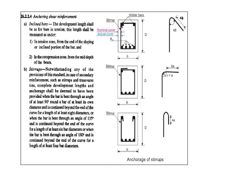
11. Shear Reinforcement v. Flexural member should be capable of developing its full moment capacity rather than having its strength limited by premature shear failure. v. Further in an overloading scenario failure should not be sudden and explosive in nature. v. Special shear reinforcement is used to enhance shear strength and induce ductile failure mechanism. v reinforcement, also known as web reinforcement may consist of any one As. Shear per Cl. 40. 4 of the following systems. • stirrups perpendicular to the beam axis; • stirrups inclined (at 45° or more) to the beam axis • longitudinal bars bent-up (usually, not more than) at Ends anchored properly longitudinal bars to develop the yield strength in 45° to 60° to thearound beam axis, tension combined with stirrups.

12. Shear Resistance of Stirrups This is evaluated based on idealization of a RC beam as a plane truss consisting of a series of reinforcing steel tensile ties and concrete compressive struts, interconnected at nodes to form a truss capable of transmitting the loads to the supports. A. Plane Truss Model Crack pattern due to flexure and shear Original Truss model Truss is formed by lumping all the stirrups cut by section aa into one vertical member and all diagonal concrete struts cut by section bb into one compression diagonal inclined at 450 Variable angle Truss model Angle of inclination of concrete struts generally varies from 250 to 650 depending upon arrangement of rebars.

B. Beams with Inclined Stirrups Diagonal Crack with horizontal projection ‘p’ and inclined length, i= p/cos , is crossed by inclined bars, horizontally spaced ‘sv ‘apart. Let rebar inclination = , crack orientation= and ‘a’ be the distance between successive rebars measured parallel to the crack direction. AB = a cos D a A sv B C BD = a sin BC = BD cot = a sin cot AC = sv = a cos + a sin cot = a sin ( cot + cot a = sv / sin ( cot + cot )

Let ‘n’ be the number of bars crossing the crack ; n=IS 456 CL 40. 4 recommendations i/a n = [p / cos ] sin ( cot + cot ) / sv n = p [ 1 + tan cot ]/ sv Total shear resistance , Vus = n x fy x Asv x sin Vus = fy Asv p [sin + cos tan ] / sv Assuming usual crack inclination 450 and p d and fy = 0. 87 fy + cos ] sv 0 us = 0. 87 f y A sv d [sin. Stirrups C. VBeams with vertical /=90 Vus = 0. 87 fy Asv d / sv D. Beams with Inclined bars ( Bent-up) Vus = 0. 87 fy Asv sin

13. Limits of shear rebars or Limiting value of Ultimate Shear Resistance of concrete v Yielding of the shear reinforcement at the ultimate limit state is essential to ensure a ductile failure. v However, such a failure will not occur if the shear reinforcement provided is excessive as section becomes stronger in diagonal tension compared to diagonal compression v Hence, a shear -compression failure may occur even before the shear reinforcement has yielded. v Cl. 40. 2. 3 has imposed a limit on the resistance Vus from shear reinforcement, by limiting the ultimate shear resistance of concrete to c, max values given in Table 20. if c < v < c max , then resistance from rebars can be supplemented else section need to be redesigned

Example 3 : Design shear reinforcement for Example 2 560

Example 4 : Verify the adequacy of RC beam in shear with following design data C Critical section for Shear At curtailment location. L b = 250 mm, d = 399 mm, D = 450 2 -#20 mm 399 660 84. 3 1 -#25 + 2 -#20 30 00 DL = 15. 0 k. N/m, LL = 13. 1 k. N/m fy = 415 MPa, fck = 25 MPa Shear Rebars = 8 @ 200, fy = 250 MPa Support width = 230 mm 1. Ultimate shear Vu at different sections At support CL = (15 + 13. 1) x 3 = 84. 3 k. N , At midspan = 0 At curtailment location = 84. 3 x (3 - 0. 66) / 3 = 65. 754 k. N At critical section ; d from support face = 84. 3 x (3 - 0. 115 - 0. 399) / 3 = 69. 9 k. N CL 22. 6. 21.
 = 69. 9")
2. Check adequacy of section • v = V / (bd) = 69. 9 x 1000 / (230 x 399) = 0. 76 Mpa < τ u concrete). c, max = 3. 1 MPa (for M 25 BEAM size OK 3. Design shear resistance at critical section • Ast = 2 - #20 = 628 mm 2 , pt = 100 Ast/bd = 100 x 628 /( 250 x 399) = 0. 63 ; Table 19 - τc = 0. 536 MPa • Shear Resistance of Concrete : Vc = 0. 536 x 250 x 399 = 53. 47 k. N • Shear Resistance by Stirrups: Vus = 0. 87 x 250 x 2 x 50. 26 x 399 / 200 = 43. 62 k. N CL 40. 4 • Vs = Vc + Vus = 97. 1 k. N > 69. 9 KN • Asv min / Sv = 0. 4 x 250 /(0. 87 x 250) = 0. 46 OK • Asv prov / Sv = 2 x 50. 26 / 200 = 0. 5 > 0. 46

Sv max = 0. 75 x 399 = 299 mm or 300 mm whichever is less Sv prov = 200 < 299 5. Check OK shear strength at bar cut-off point CL 26. 2. 3. 2 • Max. Shear resistance of beam = 97. 1 k. N • (2/3) x 97. 1 = 64. 73 k. N • At curtailment location Vu = 65. 754 k. N > 64. 73 Cl 26. 2. 3. 2 (a) • Hence additional stirrup area is provided along terminated bar over a distance from the cutoff point = (3/4)d = 300 mm Cl 26. 2. 3. 2 (b) • Area of cutoff bar (1 -#25) = 491 mm 2 • Total Area of bar at cutoff section (1 -#25 + 2 - #20) = 1119 mm 2 • b = 491 / 1119 = 0. 44 , S = 399 /( 8 x 0. 44) = 113 mm

4 - 2 L - #8 @ 100 extra stps CL 1 -#25 + 2 -#20 66 0 30 00
- Slides: 41