UNITIII OPTICAL SOURCES COUPLING Emission of light Optical

 Emission of light, (in the form of a photon)")

 • Physical dimensions to suit the")


 – Edge Emitting LED’s (EELED)")


 A superluminescent diode (SLED or SLD) is an edge-emitting semiconductor light")


 Energy absorbed from the")


 cavity")

 E 2 -E 1<Fc-Fv (population inversion) g (1/L)ln(1/R)+ (net gain)")

 Mode Separation g(λ) Longitudinal Modes")


![Coupling Efficiency [5 -1] Source Optical Fiber](https://slidetodoc.com/presentation_image_h/26c275c1295b0ac942182afadaccf018/image-36.jpg "Coupling Efficiency [5 -1] Source Optical Fiber")
 of the source B= Optical power radiated from a unit area of")


- Slides: 46
UNIT-III OPTICAL SOURCES & COUPLING
Emission of light (Optical Source) Emission of light, (in the form of a photon) can take place either spontaneously or it can be stimulated by the presence of another photon of the right energy level. For spontaneous or stimulated emission to occur, energy must be supplied to boost the electron from its low energy state to a higher energy state. The energy can come from many sources: Heat (Incandescent light), Electrical Discharge (D 2, Hg, Na lamps), Electrical Current (LED, LD), Bioluminescence (Fire fly- luciferase enzyme)
OPTICAL SOURCES: Optical Source find applications in the area of medical, automotive, analytical equipments, communications and industry. Types of Optical Source Tungsten, Deuterium, Mercury, Hollow Cathode Lamp Optical Source specifically suited to FO systems are: Light Emitting Diode (SLED, ELED, SLD) Laser Diode (DFB, DBR)
Optical Source Requirement for Performance (For Fiber Optics) • Physical dimensions to suit the optical fiber • Narrow radiation pattern (beam width) • Linearity (output light power proportional to driving current) • Ability to be directly modulated by varying driving current • Fast response time • Adequate output power into the fiber • Narrow spectral width (or line width) • Stability and efficiency • Driving circuit issues • Reliability and cost
Basic LED operation • A PN junction acts as the active or recombination region. • When the PN junction is forward biased, electrons and holes recombine either radiatively (emitting photons) or non-radiatively (emitting heat). This is simple LED operation. • Emitted wavelength depends on bandgap energy • Transitions can take place from any energy state in either band to any state in the other band. This results in a range of different wavelengths produced in this spontaneous emission. This accounts for the fact that LEDs produce a range of wavelengths. Typically the range is about 80 nm or so.
Light Emitting Semiconductors Material Al. Ga. In. P Ga. As Al. Ga. As In. Ga. As. P Wavelength Range (µm) 0. 61 - 0. 68 0. 9 0. 8 - 0. 9 1. 0 - 1. 3 0. 9 - 1. 7 Bandgap Energy (e. V) 1. 82 - 1. 94 1. 4 - 1. 55 0. 95 - 1. 24 0. 73 - 1. 35
Homojunctions: P- type and N-type from same material G a A s P G a A s N Carriers are not confined Light is not confined Structure and index of refraction n in gallium arsenide with a junction width d LED should have a high radiance (light intensity), fast response time and a high quantum efficiency for FO system
Heterojunctions: Different p- and n- materials • Carriers are confined • Light is also confined • Single Heterojunction, Double Heterojunction. A heterojunction is a junction between two semiconductors with different bandgap energies. different The difference in bandgap energies creates a one-way barrier. Charge carriers (electrons or holes) are attracted over the barrier from the material of higher bandgap energy to the one of lower bandgap energy. Gallium Arsenide-Aluminum Gallium Arsenide single heterojunction
Double Heterojunction Confining and Guiding the Light within the Device Within the device the light must be confined and directed to the exit aperture so that it can be directed into the fiber which is done using insulating materials Si. O 2 to confine the active region and the current path. The active layer in a heterostructure has a higher refractive index. This junction forms a mirror layer and helps to confine the light to the active layer. For this reason, the outer layers are often called “confinement layers”
Types of LED Structures – Surface Emitting LED’s (SLED) – Edge Emitting LED’s (EELED) – Superluminescent LED’s (SLD) Confining and Guiding the Light within the Device In both types of LED (SLED and ELED) a combination of insulating materials and junctions is used to: 1. Guide the current flow to a small “active region” and 2. Guide the light produced out of the device and into an easy position for coupling to a fiber.
Surface-emitting LED The active region is limited to a circular section that has an area compatible with the fiber-core end face.
Surface Emitting LED • The surface-emitting LED is also known as the Burrus LED in honor of C. A. Burrus, its developer. • In SLEDs, the size of the primary active region is limited to a small circular area of 20 micron to 50 micron in diameter. • The primary active region is below the surface of the semiconductor substrate perpendicular to the axis of the fiber. • A well is etched into the substrate to allow direct coupling of the emitted light to the optical fiber. The etched well allows the optical fiber to come into close contact with the emitting surface.
Edge-emitting LED Edge-emitting double-heterojunction LED. The output beam is lambertian in the plane of the pn-junction ( ||) and highly directional perpendicular to the pn-junction
Edge-emitting LED Have advantage of transparent guiding layers with a very thin active layer (50 to 100 m). This reduces self absorption and narrows the beam divergence. Light is emitted at one end face only. Couple more power to small NA fibers Higher data rates>100 Mbps, better modulation Multimode and Single Mode fibers ELEDs provide narrower linewidth than SLED High radiance
Superluminescent LEDs Significant benefits over both SLEDs and ELEDs for OFS SLDs Provide • High output power • Directional output beam • Narrow spectral linewidth One end is made optically lossy to prevent reflections and thus suppress lasing. Injection current increased until stimulated emission i. e. amplification occurs without feedback.
Superluminescent Diode (SLD) A superluminescent diode (SLED or SLD) is an edge-emitting semiconductor light source based on superluminnescence. It combines the high power and brightness of laser diodes with the low coherence of conventional LED. Its emission band is 5– 100 nm wide.
Comparision : SLEDs Vs ELEDs SLED’s generally radiate more power into air (2. 5 to 3 times) than ELED’s since the emitted light is less affected by re-absorption. SLED’s couples more optical power into large NA (greater than 0. 3) than ELED where as the opposite is true for low NA’s. Less coupling efficiency in SLED’s as compare to ELED’s have better modulation bandwidth than SLED’s ELEDs have narrower bandwidth than SLED’s.
LED Characteristics LED is forward biased, its current increases rapidly and must be controlled to prevent destruction of the device. The light output is quite linearly proportional to the current, so it can be precisely modulated. Full Width Half Max, Peak Wavelength, Forward current, Rise time, Luminous intensity (Flux(lm)), LED radiation pattern
LED Power & Efficiency Spontaneous emission allows nonradiative recombination to take place within the structure due to imperfections and impurities Internal Quantum Efficiency • 50% for simple homojunctions • 60 to 80% with DH structures Internal quantum efficiency : Ratio of radiative recombination rate to the total recombination rate int rr rr Rr rt rr rnr R t Rr is the total number of radiative recombination per second R r int R t int i e i - forward biased current to the p-n junction
Rr is equivalent to number of photons generated per second and each photon has an energy equal to h , then optical power generated internally by the LED is i Pint R r h int h e In terms of wavelength Pnti int ic h W e A linear relationship between the optical power generated in the LED and the drive current into the device
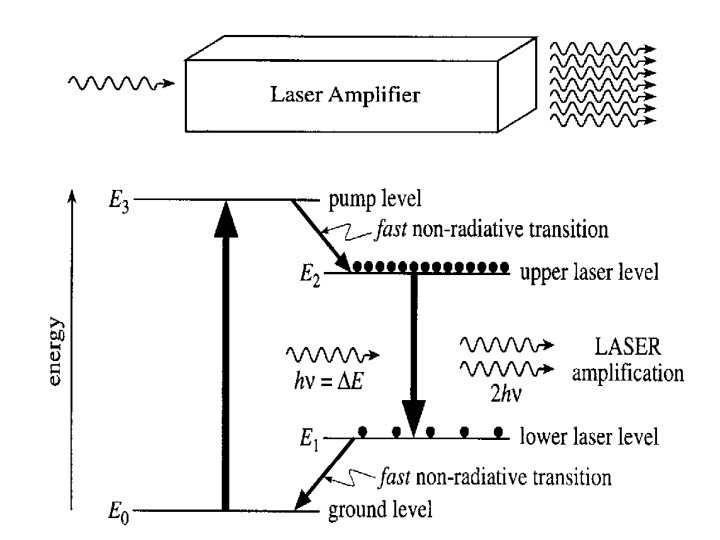
LASER DIODE LASER is an acronym for “Light Amplification by the Stimulated Emission of Radiation”. • Coherent light • Narrow beam width • Lasers can produce high output power. In communication applications, semiconductor lasers of power up to about 20 milliwatts are available. • Because laser light is Coherent, a high percentage (50% to can be coupled into the fiber. 80%)
LASER: Basic Operation Laser Transition Processes (Stimulated and Spontaneous Emission) Energy absorbed from the incoming photon Random release of energy Coherent release of energy
Conditions for Large Stimulated Emissions All three processes occur together with a balance between absorption and emission. Absorption and Emission process in steady state of material Two conditions to be satisfied for stimulated emissions to overwhelm the spontaneous emissions are: The population of excited level should be greater that at the lower energy level and The radiation density in the medium should be very large.
Population Inversion • At thermal equilibrium : Photon absorption and emission processes take place side by side, but because N 1>N 2 ; absorption dominates. • Laser operation requires stimulated emission exclusively. • To achieve a high percentage of stimulated emission, a majority of atoms should be at the higher energy level than at the lower level. • Energy is to be supplied somehow to the laser medium to raise atoms from the lower level to the excited level • The process by which atoms are raised from the lower level to the upper level is called pumping.
Basic Structure Homojunction device with cleaved ends demand for high threshold current density ( >104 A cm-2) due to lack of carrier containment - inefficient light sources Schematic diagram of a homojunction Ga. As injection laser with a Fabry-Perot cavity
How a Laser Works
Fabry-Perot Laser (resonator) cavity
Mirror Reflections
Conditions for gain (lasing) E 2 -E 1<Fc-Fv (population inversion) g (1/L)ln(1/R)+ (net gain) =2 n. L/p, p an integer (phase coherence) Reflectivity Longitudinal mode spacing
Quantum efficiency Internal quantum efficiency i, photons emitted per recombination event, determined empirically to be 0. 65 0. 05 for diode lasers External quantum efficiency e given by
Laser Output Spectrum (Center Wavelength) Mode Separation g(λ) Longitudinal Modes
Optical output vs. drive current of a laser External Efficiency Depends on the slope Threshold Current
Laser threshold depends on Temperature
Comparison between LED and LASER
Coupling Efficiency [5 -1] Source Optical Fiber
Radiance (Brightness) of the source B= Optical power radiated from a unit area of the source into a unit solid angle [watts/(square centimeter per stradian)]
Surface emitting LEDs have a Lambertian pattern:
Edge emitting LEDs and laser diodes radiation pattern For edge emitting LEDs, L=1
Power Coupled from source to the fiber
Power coupled from LED to the Fiber
Power coupling from LED to step-index fiber Total optical power from LED:
Examples of possible lensing schemes used to improve optical source-to-fiber coupling efficiency
Fiber - to- Fiber Joints Interconnect fiber in low loss manner Joints: There are two types of joints Optical Connector (Temporary Connection) Optical Splices (Permanent Connection) OPTICAL CONNECTORS Connectors are mechanisms or techniques used to join an optical fiber to another fiber or to a fiber optic component Connectors use variety of techniques: Screw on, bayonet-mount, push-pull configurations, butt joint and expanded beam fiber connectors. Butt Joint Connectors 1. Straight-Sleeve: In straight sleeve mechanism, the length of the sleeve and guided ferrules determines the end separation of two fibers. Below Fig. shows straight sleeve alignment mechanism of fiber optic connectors.
Tapered-Sleeve/Bi conical. In tapered sleeve or bi conical connector mechanism, a tapered sleeve is used to accommodate tapered ferrules. The fiber end separations are determined by sleeve length and guide rings. The below figure shows tapered sleeve fiber connectors
V-groove optical fiber splicing