UNITII Macro and Macro processor Macro Macro instructions


 A 2,")


 Positional argument Argument")
 keyword arguments � This allows reference to dummy arguments by name as")


:")
 & �A")
: � � � ALA is used during both Pass 1")


")


 Consider the following example: : MAIN START EXTRN SUBROUT -----L 15,")

 loader used in IBM 7094, IBM 1130, etc. �")
 SOURCE PROGRAM REL. ADDR MAIN EXTRN ST L BAL C")
 Absolute Relative Address 400 0 404 4 408 8 412")
 � Drawbacks : : 1) The transfer vector linkage is")
 ESD TXT RLD END FIG: - OBJECT DESK FOR A")
 � ADVATAGES: : 1)It allows the programmer multiple procedure & data")


- Slides: 65
UNIT-II
Macro and Macro processor � Macro: �Macro instructions are single line abbreviations for group of instructions. � Using a macro, programmer can define a single “instruction” to represent block of code.
MACRO ---- Start of definition INCR ---- Macro name A 1, DATA A 2, DATA ------Sequence of instructions to be A 3, DATA abbreviated MEND ---- End of definition
Macro Expansion � Replacement of macro call by corresponding sequence of instructions is called as macro expansion
Source Macro Expanded source : INCR : A 1, data : A 2, data : A 3, data : MEND : : A 1, Data : A 2, Data INCR A : : INCR : : A 1, Data : A 2, Data data DC : : END 3, Data F’ 5’ A 3, Data data DC F ‘ 5’
Features of macro facility Macro instructions arguments : : A 1, data 1 A 2, data 1 A 3, data 1 : : A 1, data 2 A 2, data 2 A 3, data 2 : Data 1 DC F’ 5’ Data 2 DC F’ 6’
Source MACRO INCR &arg (Macro name with A 1, &arg one argument) A 2, &arg A 3, &arg MEND : : INCR data 1 (use of data 1 as : operand) : INCR data 2 (use of data 1 as : operand) data 1 DC F’ 5’ data 2 DC F’ 6’ : END Expanded Source : : : A 1, data 1 A 2, data 1 A 3, data 1 : A 1, data 2 A 2, data 2 A 3, data 2 : : data 1 DC F’ 5’ data 2 DC F’ 6’
Example: more than one arguments. Loop 1 A 1, data 1 A 2, data 2 A 3, data 3 : Loop 2 A 1, data 3 A 2, data 2 A 3, data 1 : data 1 DC F’ 5’ data 2 DC F’ 6’
Source MACRO Expanded source : & lab 1 INCR & arg 1, & arg 2, & arg 3 : & lab 1 A 1, &arg 1 : A 2, &arg 2 : A 3, &arg 3 : MEND : : : LOOP 1 A 1, data 1 A 2, data 2 A 3, data 3 INCR data 1, data 2, data 3 : : : LOOP 2 INCR data 3, data 2, data 1 LOOP 2 A 1, data 3 : A 2, data 2 : A 3, data 1 DC F ‘ 5’ : data 2 F ‘ 6’ data 1 DC F ‘ 5’ F ‘ 7’ data 2 DC F ‘ 6’ DC data 3 DC F ‘ 7’
Two ways of specifying arguments to a macro call � A) Positional argument Argument are matched with dummy arguments according to order in which they appear. � INCR A, B, C � ‘A’ replaces first dummy argument � ‘B’ replaces second dummy argument � ‘C’ replaces third dummy argument
� B) keyword arguments � This allows reference to dummy arguments by name as well as by position. � e. g. � INCR &arg 1 = A, &arg 3 = C, &arg 2 =’B’ � e. g. � INCR &arg 1 = &arg 2 = A, &arg 2 =’C’
Conditional macro expansion � � � This allows conditional selection of machine instructions that appear in expansion of macro call. The macro processor pseudo op-codes AIF and AGO help to do conditional macro expansion. AIF is conditional branch pseudo op, it performs arithmetic test and branch only if condition is true. AGO is unconditional pseudo op or it is like go to statement. Both statements specify a label appearing in some other instruction within macro definition. These are macro processor directives and they do not appear in expanded source code
Source Program : MACRO & arg 0 INCR & count, & arg 1, & arg 2, & arg 3 & arg 0 A 1, &arg 1 AIF (& Count EQ. 1). FINAL A 2, & arg 2 AIF (&count EQ 2). FINAL A 3, &arg 3. FINAL MEND : LOOP 1 INCR 3, data 1, data 2, data 3 : : LOOP 2 INCR 2, data 3, data 2 : LOOP 3 INCR 1, data 1 : data 1 DC ‘ 5’ data 2 DC ‘ 6’ data 3 DC ‘ 7’ Expanded Program LOOP 1 A 1, data 1 A 2, data 2 A 3, data 3 : : LOOP 2 A 1, data 3 A 2, data 2 : : LOOP 3 A 1, data 1 : data 1 DC ‘ 5’ data 2 DC ‘ 6’ data 3 DC ‘ 7’ :
Macro-calls within macro � Macros are abbreviations of instruction sequence. Such abbreviations are also present within other macro definition.
Macro-calls within macro
Source Code : : MACRO ADD 1, &arg L 1, &arg A 1, = F ‘ 10’ ST 1, &arg MEND MACRO ADDS &arg 1, &arg 2, arg 3 ADD 1 &arg 1 ADD 1 &arg 2 ADD 1 &arg 3 MEND : : ADDS data 1, data 2, data 3 : : data 1 DC F‘ 5’ data 2 DC F‘ 6’ data 3 DC F‘ 7’ END Expanded code (level 1) Expansion of ADDS : : ADD 1 data 1 ADD 1 data 2 ADD 1 data 3 : : data DC F ‘ 5’ data DC F ‘ 6’ data DC F ‘ 7’ END Expanded code (level 2)
Source Code : : MACRO ADD 1, &arg L 1, &arg A 1, = F ‘ 10’ ST 1, &arg MEND MACRO ADDS &arg 1, &arg 2, arg 3 ADD 1 &arg 1 ADD 1 &arg 2 ADD 1 &arg 3 MEND : : ADDS data 1, data 2, data 3 : : data 1 DC F‘ 5’ data 2 DC F‘ 6’ data 3 DC F‘ 7’ END Expanded code (level 1) Expanded code (level 2) Expansion of ADD 1 Expansion of ADDS : : ADD 1 data 1 ADD 1 data 2 ADD 1 data 3 : : data DC F ‘ 5’ data DC F ‘ 6’ data DC F ‘ 7’ END L 1, data 1 A 1, = F ‘ 10’ ST 1, data 1 L 1, data 2 A 1, = F ‘ 10’ ST 1, data 2 L 1, data 3 A 1, = F ‘ 10’ ST 1, data 3 data 1 data 2 data 3 END DC F‘ 5’ DC F‘ 6’ DC F‘ 7’
Macro-instructions defining macros
Macro-instructions defining macros � � � � Macro-definition, which itself is a sequence of instruction, can be abbreviated by using macro. It is important to note that inner macro is not defined until the outer macro is called. The user might call the above macro with the statement. DEFINE-MACRO ADD 1 When this call is executed then the macro ADD 1 will be defined. So after the above call user can call the ADD 1 macro in following way. ADD 1 data 1 The macro processor will generate the sequence L 1, data 1 A 1, =F’ 0’ ST 1, data 1.
Implementation � There are four basic task that a macro-processor must perform � Recognize macro definition A macro instruction processor must recognize macro definition identified by MACRO & MEND pseudo – operations. � Save the Definition The processor must store the macro – definitions which will be needed at the time of expansion of calls. � Recognize the Macro call The processor must recognize macro calls that appear as operation mnemonics. � Expand calls & substitute arguments The macro call is replaced by the macro definition. The dummy arguments are replaced by the actual data.
Two pass Macro Processor � General Design Steps � Step 1: Specification of Problem: � Step 2 Specification of databases: � Step 3 Specification of database formats � Step 4 : Algorithm
Specify the problem � In Pass-I the macro definitions are searched and stored in the macro definition table and the entry is made in macro name table � In Pass-II the macro calls are identified and the arguments are placed in the appropriate place and the macro calls are replaced by macro definitions.
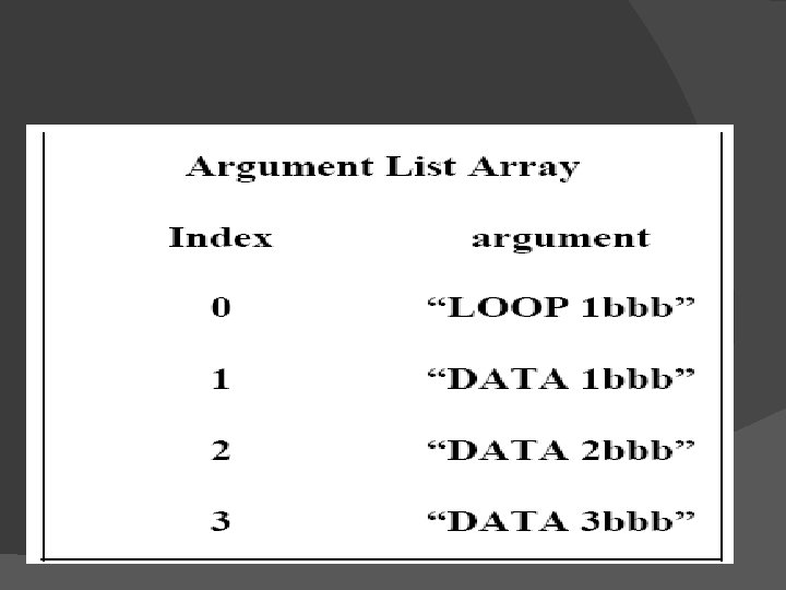
Specification of databases: Pass 1: � The input macro source program. � The output macro source program to be used by Pass 2. � Macro-Definition Table (MDT), to store the body of macro defns. � Macro-Definition Table Counter (MDTC), to mark next available entry MDT. � Macro- Name Table (MNT), used to store names of macros. � Macro Name Table counter (MNTC), used to indicate the next available entry in MNT. � Argument List Array (ALA), used to substitute index markers for dummy arguments before storing a macrodefns.
Specification of databases: � � � � Pass 2: The copy of the input from Pass 1. The output expanded source to be given to assembler. MDT, created by Pass 1. MNT, created by Pass 1. Macro-Definition Table Pointer (MDTP), used to indicate the next line of text to be used during macro-expansion. Argument List Array (ALA), used to substitute macro-call arguments for the index markers in the stored macro-defns
Specification of database format: -
� MDT is a table of text lines. � Every line of each macro definition except the MACRO line, is stored in the MDT (MACRO line is useless during macro-expansion) � MEND is kept to indicate the end of the depns. � The macro-name line is retained to facilitate keyword argument replacement.
Macro Names Table (MNT):
� Each MNT entry consists of �A character string (the macro name) & �A pointer (index) to the entry in MDT that corresponds to the beginning of the macrodefinition. (MDT index)
Argument List Array (ALA): � � � ALA is used during both Pass 1 & Pas 2 but for some what reverse functions. During Pass 1, in order to simplify later argument replacement during macro expansion, dummy arguments are replaced with positional indicators when defn is stored. Ex. # 1, # 2, # 3 etc. The ith dummy argument on the macro-name is represented in the body by #i. These symbols are used in conjunction with ALA prepared before expansion of a macro-call. Symbolic dummy argument are retained on macroname to enable the macro processor to handle argument replacement byname rather by position.
During pass-I
During Pass-II During Pass 2 it is necessary to substitute macro call arguments for the index markers stored in the macro. � Thus upon encountering the call expander would prepare a ALA as shown below: � LOOP 1 NCR DATA 1, DATA 2, DATA 3, } � → Call in main prog. � → ALA is prepare of after this call is encountered. �
Algorithm � � � Pass 1 of macro processor makes a line-by-line scan over its input. Set MDTC = 1 as well as MNTC = 1. Read next line from input program. If it is a MACRO pseudo-op, the entire macro definition except this (MACRO) line is stored in MDT. The name is entered into Macro Name Table along with a pointer to the first location of MDT entry of the definition. When the END pseudo-op is encountered all the macro-defns have been processed, so control is transferred to pass 2
MDTC 1 MNTC 1 Enter Macro Name and Current value of MDTC in MNT MDTC+1
Algorithm for Pass – 2 � � � � This algorithm reads one line of i/p prog. at a time. for each Line it checks if op-code of that line matches any of the MNT entry. When match is found (i. e. when call is pointer called MDTF to corresponding macro defns stored in MDT. The initial value of MDTP is obtained from MDT index field of MNT entry. The macro expander prepares the ALA consisting of a table of dummy argument indices & corresponding arguments to the call. Reading proceeds from the MDT, as each successive line is read, The values form the argument list one substituted for dummy arguments indices in the macro defn. Reading MEND line in MDT terminates expansion of macro & scanning continues from the input file. When END pseudo-op encountered , the expanded source program is given to the assembler
MDTP + 1
MACROS PROCEDURE 1 The corresponding machine code is 1 The Corresponding m/c code is written every time a macro is written only once in memory called in a program. 2 Program takes up more memory 2 Program takes up comparatively space. less memory space. 3 No transfer of program counter. 4 No overhead of using stack for 4 Overhead of using stack for transferring control. 5 Execution is fast 5 Execution is comparatively slow. 6 Assembly time is more. 6 Assembly time is comparatively less. 7 More advantageous to the programs when repeated group of instruction is too short. instructions is quite large. 3 Transferring of program counter is required.
Loaders � Loader is a program which accepts the object program decks and prepares these programs for execution by the computer and initiates the execution
The loader must perform the following functions Allocate space in memory for the program(Allocation) 2. Resolve symbolic references between object decks(Linking) 3. Adjust all address dependent locations, such as address constants, to corresponds to the allocated space (Relocation) 4. Physically place the machine instruction and data in memory(Loading) 1.
Loader A B B Data Base Program Loaded in memory ready for Execution
Loader Schemes � Compile-and-Go loader � General Loader Scheme � Absolute Loading scheme � Subroutine Linkages � Relocating Loaders � Direct Linking Loaders
Compile-and-Go Loader Source program deck
� In this scheme assembler run in one part of memory and place object instructions & data, as they are assembled, directly into their assigned memory location. � When assembly is completed, assembler causes a transfer to the starting instruction of the program
� � � Advantages: It is relatively easy to implement. Assembler simply places code into core and loader transfer control to starting instruction of newly assembled program. Disadvantages: i) A portion of memory is always occupied by assembler. That portion is unavailable to any other object program. � ii) User’s program have to be reassemble every time it is run. � iii) If source program contains sub routine written in different languages, then different assemblers have to be stored in memory ( i. e. again wastage of memory).
General Loading Scheme
General Loader Scheme � In this scheme the output of assembler is saved and loaded whenever code is to be executed. � Assembled program could be loaded, in the same area into memory where assembler was stored ( because now assembling is completed assembler is removed from main memory). � Function of loader is to accept instruction, data and other information in object format and put it into memory in executable format.
� Advantages: � No need to put assembler in main memory all the time it can be removed after assembly is completed. Assembled program is stored in secondary storage in object form � Loader is required to put object code in memory in executable format, which is smaller in size. � Every time when we run program one do not have to assembler it every time. � Even if subroutine are in different languages, their object code & linkage conventions will be in one language. � Disadvantage: Addition of a new program ‘Loader’ into system.
Absolute Loader 100 MAIN 248 400 Absolute Loader 248 MAIN SQRT 478 Object Deck 400 SQRT 478 Main Memory
Absolute Loaders: � The simplest type of loader scheme which fits to the general model is called as absolute loader. � Assembler produces object code, which is stored on secondary storage ( instead of directly loaded into main memory like in compile -&-go). � Loader in turn accepts this object code, places it into core at prescribed place by assembler for execution.
Advantages: � This scheme makes more memory available to the user, an assembler is not in memory at load time. � Simple to implement. Disadvantages: � Programmer must specify to the assembler, the address of memory location where program is to be loaded. � When program contains more than one subroutines, then programmer must remember the address of each and have to user it explicitly in other subroutines to perform subroutine linkages. � Programmer must be careful not to assign same or overlapping locations to two subroutines.
Thus in absolute loader scheme four loader functions are performed by � � Allocation - by programmer Linking - by programmer Relocation - by assembler Loading - by loader
Subroutine linkage � � � The problem is: : A MAIN program A wishes to transfer to sub-program B. However the assembler does not know this symbol and declare it as an undefined symbol (error) unless a special mechanism has been provided. This mechanism has been implemented with a directlinking or a relocating loader. The assembler pseudo-op EXTRN followed by a list of symbols indicates that these symbols are defined in another programs. Correspondingly if a symbol is defined in one program and referenced in others, we insert it into a symbol list following the pseudo-op ENTRY. The assembler will also inform the loader that these symbols may be referenced by other programs.
Subroutine linkage(Cont… 1) Consider the following example: : MAIN START EXTRN SUBROUT -----L 15, = A(SUBROUT) BALR 14, 15 // reg 14 is return addr of caller. -------END The subroutine can be defined at other location as : : SUBROUT START USING *, 15 -----BR 14 END �
Relocating loaders � To avoid possible reassembling of all subroutines when a single subroutine is changed, and to perform the task of allocation and linking for programmer, relocating loaders are developed. � In this scheme, assembler assembles each procedure segment independently and passes on the text and information after relocation & inter segment references to the loader.
Example: : BSS(Binary Symbolic Subroutines) loader used in IBM 7094, IBM 1130, etc. � The o/p of a relocating assembler using a BSS scheme is the object program & information about all programs it references. � It also provides the relocating information that needs to be changed if it is placed in an arbitrary place in core. � BSS loader scheme is used on computers with a fixed length direct address instruction format. �
5. RELOCATING LOADER(Cont… 1) SOURCE PROGRAM REL. ADDR MAIN EXTRN ST L BAL C BNE L BR START SQRT ERR 14, SAVE 1, =F ‘ 9’ 14, SQRT 1, = F ‘ 3’ ERR 14, SAVE 14 0 4 8 12 16 20 24 28 32 00 00 01 01 01 0 SAVE DS F END 34 36 40 44 0 skipped for alignment 00 temp. location 00 00 56 RELOCATION OBJECT CODE ‘SQRT’ ‘ERRb’ ST 14, 36 L 1, 40 BAL 14, 0 C 1, 44 BC 7, 4 L 14, 36 BCR 15, 14
5. RELOCATING LOADER(Cont… 2) Absolute Relative Address 400 0 404 4 408 8 412 12 416 16 420 20 424 24 428 28 432 32 436 36 440 40 444 44 BC 15, 448 BC 15, 526 ST 14, 436 L 1, 440 BAL 14, 400 C 1, 444 BC 7, 404 L 4, 436 BCR 15, 14 (TEMP LOC) 9 3 SQRT ERR 57 LENGTH = 48 BYTES. LENGTH = 78 BYTES.
5. RELOCATING LOADER(Cont… 3) � Drawbacks : : 1) The transfer vector linkage is only useful for transfers & is not well situated for loading or storing external data(data located in another procedure segments). 2) The transfer vector increases the size of the object program in memory. 58
6. DIRECT-LINKING LOADER(cont… 1) ESD TXT RLD END FIG: - OBJECT DESK FOR A DIRECT LINKING LOADER � ESD – External Symbol dictionary. � TXT – Text (contains actual assembled program). � RLD - Relocation & Linkage Directory. – contains information about those locations in the program whose contents depends on the address at which the program is placed. These information are: : � Location of each constant that needs to be changed due to relocation. � By what it has to be changed. � The operation to be performed. 59
DIRECT-LINKING LOADER(cont… 2) � ADVATAGES: : 1)It allows the programmer multiple procedure & data segments. 2)Complete freedom for the programmer to refer the data in other segments. 3)Provides flexibility in intersegment referencing & accessing ability. 4)Allows independent translations of the programs. � DISADVATAGES: : 1)It is necessary to allocate, relocate, link & load all of the subroutines each time in order to execute a program. 2)These loading are Time-consuming. 3)Although loader is smaller than assembler, it occupies some memory space. 60
OTHER LOADING SCHEMES � These includes Binders, linking loaders, Overlays & Dynamic loaders. � Binders: : - A Binder is a program that performs the same functions as that of a direct-linking loader in binding subroutines together, but rather than placing the relocated & linked text directly into memory, it outputs the text as a file or a card deck. � This o/p file to be loaded is called as “load-module”. � The functions of binders are : : Ø � Allocation, Relocation, Linking & Loading. There are 2 major classes of Binders: : �Core – image module. ( fast & simple) �Linkage Editor. (complex) 61
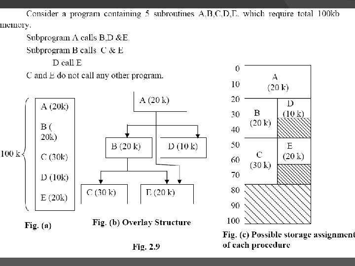
Dynamic Loading overlays � Each of the previous loader schemes assume that all of the subroutines are loaded into core at the same time. It the total amount of memory available is less than memory required by all needed subroutines, then there will be trouble.
Solution to above problem can be� Some hardware techniques like paging and segmentation are used to solve this problem � There is loading scheme called as dynamic loading which is also available to solve above problem.
� Usually different subroutines are needed at different times. E. g. PASS 1 & PASS 2 of assembler are mutually exclusive. Both can be loaded one after another, need not to be loaded at the same time. � By determining which subroutines call another, which are exclusive , we can produce an overlay structure, that will help to use memory economically.