UnitI 80386 DX Architecture History of 8086 microprocessor


 �Flags �General")


 has �Control unit �Instruction decoder �Arithmetic and Logical")


 is a 16 -bit register pointing to")


 register is a 16 -bit register containing address of")
 register is a 16 -bit register containing address of")


- Slides: 26
Unit-I 80386 DX Architecture �History of 8086 microprocessor, Concept of segmentation in 8086, 8086 Register block diagram � 80386 DX functional Block Diagram, PIN Description, Register set, Flags, Physical address space, Data types
History of 8086
Architecture of 8086 �The architecture of 8086 includes �Arithmetic Logic Unit (ALU) �Flags �General registers �Instruction byte queue �Segment registers
EU & BIU �The 8086 CPU logic has been partitioned into two functional units namely Bus Interface Unit (BIU) and Execution Unit (EU) �The major reason for this separation is to increase the processing speed of the processor �The BIU has to interact with memory and input and output devices in fetching the instructions and data required by the EU �EU is responsible for executing the instructions of the programs and to carry out the required processing
Architecture Diagram
Execution Unit �The Execution Unit (EU) has �Control unit �Instruction decoder �Arithmetic and Logical Unit (ALU) �General registers �Flag register �Pointers �Index registers
Execution Unit �Control unit is responsible for the co-ordination of all other units of the processor. �ALU performs various arithmetic and logical operations over the data. �The instruction decoder translates the instructions fetched from the memory into a series of actions that are carried out by the EU.
Execution Unit - Registers �General registers are used for temporary storage and manipulation of data and instructions �Accumulator register consists of two 8 -bit registers AL and AH, which can be combined together and used as a 16 -bit register AX �Accumulator can be used for I/O operations and string manipulation
Execution Unit - Registers �Base register consists of two 8 -bit registers BL and BH, which can be combined together and used as a 16 -bit register BX. �BX register usually contains a data pointer used for based, based indexed or register indirect addressing. �Count register consists of two 8 -bit registers CL and CH, which can be combined together and used as a 16 -bit register CX. �Count register can be used as a counter in string manipulation and shift/rotate instructions.
Execution Unit - Registers �Data register consists of two 8 -bit registers DL and DH, which can be combined together and used as a 16 -bit register DX. �Data register can be used as a port number in I/O operations. �In integer 32 -bit multiply and divide instruction the DX register contains high-order word of the initial or resulting number.
Execution Unit - Registers
Execution Unit - Flags
Execution Unit - Flags
Flags �Conditional Flags: Set or reset by EU on the basis of the results of arithmetic or logic operation �Control Flags (TF, IF, DF)
Execution Unit - Pointers �Stack Pointer (SP) is a 16 -bit register pointing to program stack �Base Pointer (BP) is a 16 -bit register pointing to data in stack segment. BP register is usually used for based, based indexed or register indirect addressing. �Source Index (SI) is a 16 -bit register. SI is used for indexed, based indexed and register indirect addressing, as well as a source data addresses in string manipulation instructions. �Destination Index (DI) is a 16 -bit register. DI is used for indexed, based indexed and register indirect addressing, as well as a destination data addresses in string manipulation instructions.
Bus Interface Unit �The BIU has � Instruction stream byte queue � A set of segment registers � Instruction pointer
BIU – Instruction Byte Queue � 8086 instructions vary from 1 to 6 bytes �Therefore fetch and execution are taking place concurrently in order to improve the performance of the microprocessor �The BIU feeds the instruction stream to the execution unit through a 6 byte prefetch queue �This prefetch queue can be considered as a form of loosely coupled pipelining
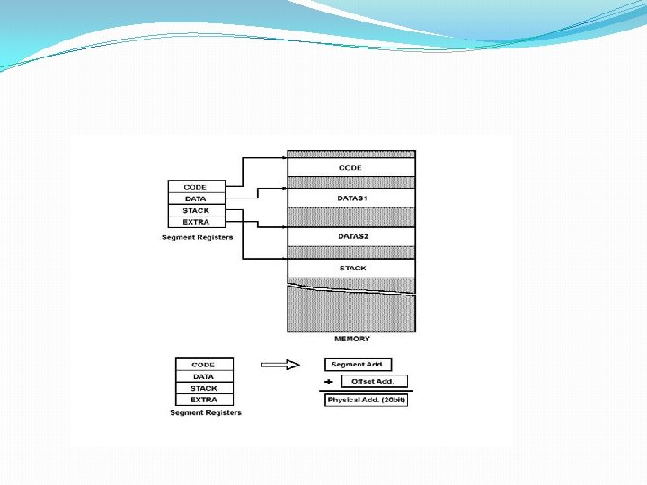
Segment Registers �The memory of 8086 is divided into 4 segments namely � Code segment (program memory) � Data segment (data memory) � Stack memory (stack segment) � Extra memory (extra segment)
Different Areas in Memory �Program memory – Program can be located anywhere in memory �Data memory – The processor can access data in any one out of 4 available segments �Stack memory – A stack is a section of the memory set aside to store addresses and data while a subprogram executes �Extra segment – This segment is also similar to data memory where additional data may be stored and maintained
Segment Registers �Code Segment (CS) register is a 16 -bit register containing address of 64 KB segment with processor instructions. �The processor uses CS segment for all accesses to instructions referenced by instruction pointer (IP) register. �Stack Segment (SS) register is a 16 -bit register containing address of 64 KB segment with program stack. �By default, the processor assumes that all data referenced by the stack pointer (SP) and base pointer (BP) registers is located in the stack segment
Segment Registers �Data Segment (DS) register is a 16 -bit register containing address of 64 KB segment with program data. �By default, the processor assumes that all data referenced by general registers (AX, BX, CX, DX) and index register (SI, DI) is located in the data segment. �Extra Segment (ES) register is a 16 -bit register containing address of 64 KB segment, usually with program data. �By default, the processor assumes that the DI register references the ES segment in string manipulation instructions
Segment Registers
Memory Segmentation
20 -bit Physical address generation
Thank You!