UNIT5 Transmission Media 1 3 6 PERFORMANCE Topics


,")


- Slides: 48
UNIT-5 Transmission Media 1
3 -6 PERFORMANCE Topics discussed in this section: ▪ Bandwidth - capacity of the system ▪ Throughput - no. of bits that can be pushed through ▪ Latency (Delay) - delay incurred by a bit from start to finish ▪ Bandwidth-Delay Product 2
Note In networking, we use the term bandwidth in two contexts. ▪ The first, bandwidth in hertz, refers to the range of frequencies in a composite signal or the range of frequencies that a channel can pass. ▪ The second, bandwidth in bits per second, refers to the speed of bit transmission in a channel or link. Often referred to as Capacity. 3
Example 3. 44 A network with bandwidth of 10 Mbps can pass only an average of 12, 000 frames per minute with each frame carrying an average of 10, 000 bits. What is the throughput of this network? Solution We can calculate throughput as The throughput is almost one-fifth of the bandwidth in this case. 4
Propagation & Transmission delay Propagation speed - speed at which a bit travels though the medium from source to destination. Transmission speed - the speed at which all the bits in a message arrive at the destination. (difference in arrival time of first and last bit) 5 Mc. Graw-Hill ©The Mc. Graw-Hill Companies, Inc. , 2000
Propagation and Transmission Delay Propagation Delay = Distance/Propagation speed Transmission Delay = Message size/bandwidth bps Latency = Propagation delay + Transmission delay + Queueing time + Processing time 6 Mc. Graw-Hill ©The Mc. Graw-Hill Companies, Inc. , 2000
Example 3. 45 What is the propagation time if the distance between the two points is 12, 000 km? Assume the propagation speed to be 2. 4 × 10⁸ m/s in cable. Solution We can calculate the propagation time as The example shows that a bit can go over the Atlantic Ocean in only 50 ms if there is a direct cable between the source and the destination. 7
Figure 3. 31 Filling the link with bits for case 1 8
Figure 3. 32 Filling the link with bits in case 2 9
Note The bandwidth-delay product defines the number of bits that can fill the link. 10
Figure 3. 33 Concept of bandwidth-delay product 11
Figure 7. 1 Transmission medium and physical layer 12
Figure 7. 2 Classes of transmission media 13
7 -1 GUIDED MEDIA Guided media, which are those that provide a conduit from one device to another, include twisted-pair cable, coaxial cable, and fiber-optic cable. Topics discussed in this section: Twisted-Pair Cable Coaxial Cable Fiber-Optic Cable 14
Figure 7. 3 Twisted-pair cable 15
Figure 7. 4 UTP and STP cables 16
Table 7. 1 Categories of unshielded twisted-pair cables 17
Connectors The most common UTP connector is RJ 45 (RJ stands for registered jack), The RJ 45 is a keyed connector, meaning the connector can be inserted in only one way. APPLICATION: • Twisted-pair cables are used in telephone lines to provide voice and data channels. • The local loop—the line that connects subscribers to the central telephone office— • commonly consists of unshielded twisted-pair cables in The DSL lines that are used by the telephone companies to provide high-data-rate connections also use the high-bandwidth capability of unshielded twisted -pair cables.
Figure 7. 5 UTP connector 19
Figure 7. 6 UTP performance 20
Figure 7. 7 Coaxial cable 21
Table 7. 2 Categories of coaxial cables 22
Figure 7. 8 BNC connectors 23
• The BNC connector is used to connect the end of the cable to a device, such as a TV set. • The BNC T connector is used in Ethernet to branch out to a connection to a computer or other device. • The BNC terminator is used at the end of the cable to prevent the reflection of the signal.
Performance: Attenuation is much higher in coaxial cable than in twistedpair cable. In other words, although coaxial cable has a much higher bandwidth Application: • Coaxial cable was widely used in analog telephone networks where a single coaxial network could carry 10, 000 voice signals. • Later it was used in digital telephone networks where a single coaxial cable could carry digital data up to 600 Mbps. • However, coaxial cable in telephone networks has largely been replaced today with fiberoptic cable.
• In the traditional cable TV network, the entire network used coaxial cable. • Later, however, cable TV providers replaced most of the media with fiber-optic cable; hybrid networks use coaxial cable only at the network boundaries, near the consumer premises. • Cable TV uses RG-59 coaxial cable. • Another common application of coaxial cable is in traditional Ethernet LANs Because of its high bandwidth, and consequently high data rate, coaxial cable was chosen for digital transmission in early Ethernet LANs. • The 10 Base-2, or Thin Ethernet, uses RG-58 coaxial cable with BNC connectors to transmit data at 10 Mbps with a range of 185 m.
Figure 7. 9 Coaxial cable performance 27
Figure 7. 10 Fiber optics: Bending of light ray 28
Figure 7. 11 Optical fiber 29
Figure 7. 12 Propagation modes 30
Figure 7. 13 Modes 31
Table 7. 3 Fiber types 32
Figure 7. 14 Fiber construction 33
Figure 7. 15 Fiber-optic cable connectors 34
Performance The plot of attenuation versus wavelength shows a very interesting phenomenon in fiber-optic cable. Attenuation is flatter than in the case of twisted-pair cable and coaxial cable.
Figure 7. 16 Optical fiber performance 38
Mc. Graw-Hill ©The Mc. Graw-Hill Companies, Inc. , 2000
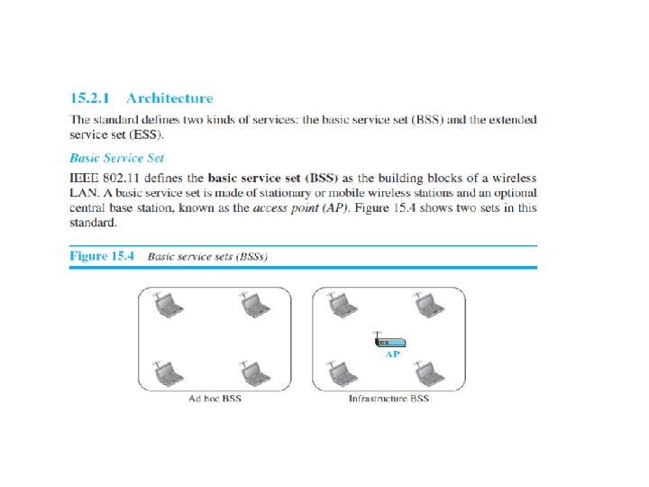
■ Ø Ø ■ ■ The standard defines two kinds of services: The basic service set (BSS) and The extended service set (ESS). The BSS without an AP is a stand-alone network and cannot send data to other BSSs. It is called an ad hoc architecture. In this architecture, stations can form a network without the need of an AP; they can locate one another and agree to be part of a BSS. A BSS with an AP is sometimes referred to as an infrastructure BSS.