UNIT4 HIGHWAY MATERIALS AND CONSTRUCTION PRACTICE Sub grade

UNIT-4 HIGHWAY MATERIALS AND CONSTRUCTION PRACTICE Sub grade soil Soil is an accumulation or deposit of earth material, derived naturally from the disintegration of rocks or decay of vegetation, that can be excavated readily with power equipment in the field or disintegrated by gentle mechanical means in the laboratory. The supporting soil beneath pavement and its special under courses is called sub grade. Undisturbed soil beneath the pavement is called natural sub grade. Compacted sub grade is the soil compacted by controlled movement of heavy compactors.

SOIL TEST - CBR Test 1. The representative soil sample is sieved through 19 mm sieve and retained on 4. 75 mm sieve. About 5 kg of soil is taken and mixed with optimum moisture content (OMC). 2. Clamp the mold to the base plate; attach the extension collar and weight. Insert the spacer disk into the mold and place a coarse filter paper on the top of the disk. 3. Compact the soil-water mixture into the mould in 3 equal layers to give a height of 127 mm compact each layer in the 10 blows, 30 blows and 65 blows for each sample. 4. Determine the water content of the soil mixture. 5. Remove the extension collar, and using on straight edge, trim the compacted soil even with the top of the mold surface. Remove the spacer disk and weigh the mold with sample.

6. Place the mold with soil on the CBR machine and place the surcharge weight of 2. 5 kg. Seat the penetration piston, set the dial gauges for load and penetration. 7. Apply the loads to the penetration piston at the rate of 1. 25 mm/min and record the load at 0. 0, 0. 5, 1. 0, 1. 5, 2. 0, 2. 5, 3. 0, 4. 0, 5. 0, 7. 5, 10. 0 and 12. 5 mm penetration respectively. 8. Detach the mould from the loading equipment. Take about 20 to 50 g of soil from the top 3 cm layer and determine the moisture content.

If the value of 2. 5 mm is greater than that of 5. 0 mm penetration, the former is adopted. If the CBR value obtained from test at 5. 0 mm penetration is higher than that at 2. 5 mm, then the test is to be repeated for checking. If the check test again gives similar results, then higher value obtained at 5. 0 mm penetration is reported as the CBR value. The average CBR value of three test specimens is reported as the CBR value of the sample.

FIELD DENSITY TEST Calibration of the Cylinder 1. Fill the sand pouring cylinder with clean sand so that the level of the sand in the cylinder is within about 10 mm from the top. Find out the initial weight of the cylinder plus sand (W 1) and this weight should be maintained constant throughout the test for which the calibration is used. 2. Allow the sand of volume equal to that of the calibrating container to run out of the cylinder by opening the shutter, close the shutter and place the cylinder on the glass sand takes place in the cylinder close the shutter and remove the cylinder carefully. Weigh the sand collected on the glass plate. Its weight(W 2) gives the weight of sand filling the cone portion of the sand pouring cylinder. Repeat this step at least three times and take the mean weight (W 2) Put the sand back into the sand pouring cylinder to have the same initial constant weight (W 1)
 of the container")
Determination of Bulk Density of Soil 3. Determine the volume (V) of the container be filling it with water to the brim. Check this volume by calculating from the measured internal dimensions of the container. 4. Place the sand poring cylinder centrally on yhe of the calibrating container making sure that constant weight (W 1) is maintained. Open the shutter and permit the sand to run into the container. When no further movement of sand is seen close the shutter, remove the pouring cylinder and find its weight (W 3). Determination of Dry Density of Soil In Place 5. Approximately 60 sq. cm of area of soil to be tested should be trimmed down to a level surface, approximately of the size of the container. Keep the metal tray on the level surface and excavate a circular hole of volume equal to that of the calibrating container.

Collect all the excavated soil in the tray and find out the weight of the excavated soil (Ww). Remove the tray, and place the sand pouring cylinder filled to constant weight so that the base of the cylinder covers the hole concentrically. Open the shutter and permit the sand to run into the hole. Close the shutter when no further movement of the sand is seen. Remove the cylinder and determine its weight (W 3). 6. Keep a representative sample of the excavated sample of the soil for water content determination. Weight of wet soil from hole Ww gm Weight of sand + cylinder before pouring W 1 gm Weight of sand + cylinder after pouring W 4 gm Weight of sand in hole Wb = (W 1 -W 2 -W 4) gm Bulk density gb = (Ww /Wb) gs gm/cc

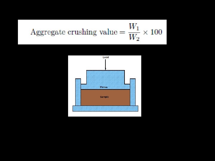
TESTS ON AGGREGATES Crushing test The aggregate crushing value provides a relative measure of resistance to crushing under gradually applied crushing load. The test consists of subjecting the specimen of aggregate in standard mould to a compression test under standard load conditions. Dry aggregates passing through 12. 5 mm sieves and retained 10 mm sieves are filled in a cylindrical measure of 11. 5 mm diameter and 18 cm height in three layers. Each layer is tampered 25 times with at standard tamping rod. The test sample is weighed and placed in the test cylinder in three layers each layer being tampered again. The specimen is subjected to a compressive load of 40 tonnes gradually applied at the rate of 4 tonnes per minute. Then crushed aggregates are then sieved through 2. 36 mm sieve and weight of passing material (W 2) is expressed as percentage of the weight of the total sample (W 1) which is the aggregate crushing value.

Abrasion test The principle of Los Angeles abrasion test is to find the percentage wear due to relative rubbing action between the aggregate and steel balls used as abrasive charge. Los Angeles machine consists of circular drum of internal diameter 700 mm and length 520 mm mounted on horizontal axis enabling it to be rotated. An abrasive charge consisting of cast iron spherical balls of 48 mm diameters and weight 340 -445 g is placed in the cylinder along with the aggregates. The number of the abrasive spheres varies according to the grading of the sample. The quantity of aggregates to be used depends upon the gradation and usually ranges from 5 -10 kg. The cylinder is then locked and rotated at the speed of 30 -33 rpm for a total of 500 -1000 revolutions depending upon the gradation of aggregates.

After specified revolutions, the material is sieved through 1. 7 mm sieve and passed fraction is expressed as percentage total weight of the sample. This value is called Los Angeles abrasion value. A maximum value of 40 percent is allowed for WBM base course in Indian conditions. For bituminous concrete, a maximum value of 35 is specified.

Impact test The aggregate impact test is carried out to evaluate the resistance to impact of aggregates. Aggregates passing 12. 5 mm sieve and retained on 10 mm sieve is filled in a cylindrical steel cup of internal dia 10. 2 mm and depth 5 cm which is attached to a metal base of impact testing machine. The material is filled in 3 layers where each layer is tamped for 25 number of blows. Metal hammer of weight 13. 5 to 14 Kg is arranged to drop with a free fall of 38. 0 cm by vertical guides and the test specimen is subjected to 15 number of blows. The crushed aggregate is allowed to pass through 2. 36 mm IS sieve.
")
And the impact value is measured as percentage of aggregates passing sieve (W 2) to the total weight of the sample (W 1). Aggregates to be used for wearing course, the impact value shouldn't exceed 30 percent. For bituminous macadam the maximum permissible value is 35 percent. For Water bound macadam base courses the maximum permissible value defined by IRC is 40 percent

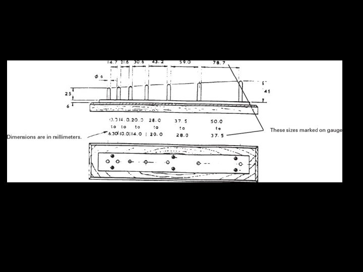
Shape tests The particle shape of the aggregate mass is determined by the percentage of flaky and elongated particles in it. Aggregates which are flaky or elongated are detrimental to higher workability and stability of mixes. The flakiness index is defined as the percentage by weight of aggregate particles whose least dimension is less than 0. 6 times their mean size. Flakiness gauge

For determining the flakiness index of aggregate. It consists of a panel having accurately cut slots of different standard lengths and width. Particle is elongated when its length (longest dimension) is more than 1. 8 of the midsize of the sieve fraction. Aggregate to be classified is separated into seven sieve fractions from 63 to 6. 3 mm, and each fraction is examined separately. Six labeled openings between pairs of metal pins measure particle from each of the six sieve cuts below 50 mm. The mass of all elongated particles (failing to pass between pins) as percent of the sample is the elongation index. Meets BS 812.

The elongation index of an aggregate is defined as the percentage by weight of particles whose greatest dimension (length) is 1. 8 times their mean dimension. This test is applicable to aggregates larger than 6. 3 mm. Discard all aggregate retained on the 50. 0 mm BS test sieve and all aggregate passing the 6. 30 mm BS test sieves Elongation gauge Select the length gauge appropriate to the size-fraction under test and gauge each particle separately by hand. Elongated particles are those whose greatest dimension prevents them from passing through the gauge
, calculate the")
From the sum of masses of the fractions in the trays(M 1), calculate the individual percentages retained on each of the various sieves. Discard any fraction whose mass is 5% or less of mass M 1. Record the mass remaining (M 2) Gauge each fraction as follows. Select the length gauge appropriate to the size-fraction under test and gauge each particle separately by hand. Elongated particles are those whose greatest dimension prevents them from passing through the gauge. Combine and weigh all Elongated particles (M 3). Elongation index = M 3 M 2 X 100

Water absorption is the difference between the apparent and bulk specific gravities or water permeable voids of the aggregates. We can measure the volume of such voids by weighing the aggregates dry and in a saturated, surface dry condition, with all permeable voids filled with water. The difference of the above two is MW. MW is the weight of dry aggregates minus weight of aggregates saturated surface dry condition. Water absorption values ranges from 0. 1 to about 2. 0 percent for aggregates normally used in road surfacing.

Polished Stone Value The Polished Stone Value of aggregate gives a measure of resistance to the polishing action of vehicle tyres under conditions similar to those occurring on the surface of a road. The action of road vehicle tyres on road surfaces results in polishing of the top, exposed aggregate surface, and its state of polish is one of the main factors affecting the resistance to skidding.

Four curved test specimens are prepared from each sample undergoing test. Each consists of 35 to 50 representative chippings of carefully controlled size supported in a rigid matrix. Fourteen specimens are clamped around the periphery of the 'road wheel' and subjected to two phases of polishing by wheels with rubber tyres. The first phase is of abrasion by a corn emery for three hours, followed by three hours of polishing with an emery flour. Two of the fourteen samples are of Control stone.
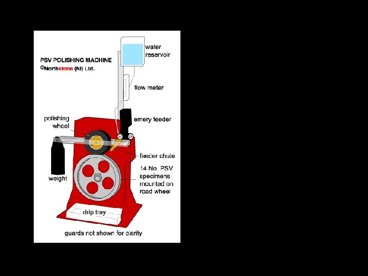

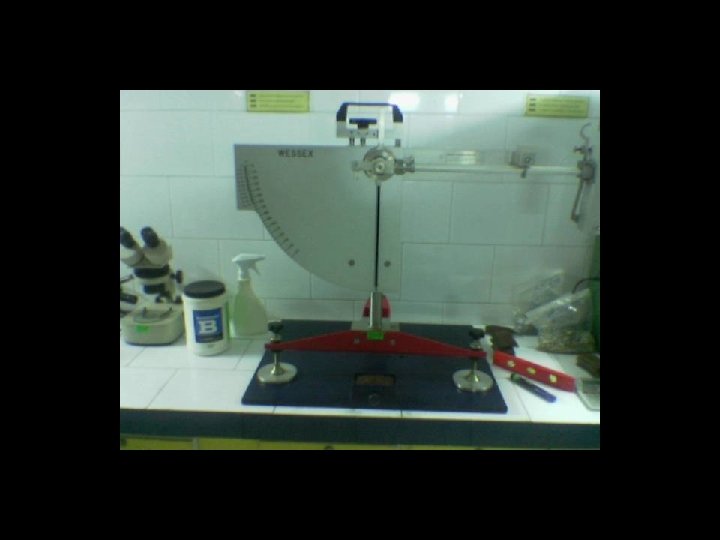
The degree of polish of the specimens is then measured by means of the portable skid resistance tester (using a special narrow slider, shorter test length and supplementary scale) under carefully controlled conditions. Control specimens are used to condition and check the slider before the test; also a pair of control specimens is included in each test run of fourteen specimens to check the entire procedure and to allow for adjustment of the result to compensate for minor variations in the polishing and or friction testing. Results are expressed as 'polished stone values' (PSVs), the mean of the four test specimens of each aggregate.

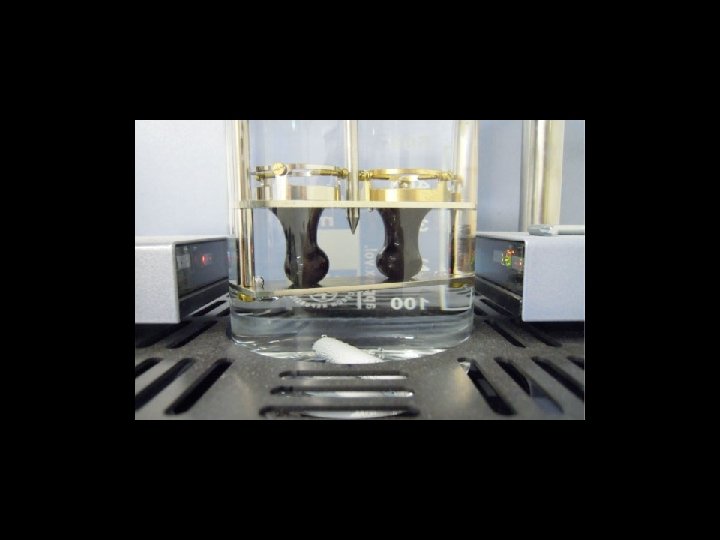
BITUMEN TESTS-Penetration test It measures the hardness or softness of bitumen by measuring the depth in tenths of a millimeter to which a standard loaded needle will penetrate vertically in 5 seconds. BIS had standardized the equipment and test procedure. In this test we examine the consistency of a sample of bitumen. 1. 2. 3. 4. 5. The penetrometer consists of a needle assembly with a total weight of 100 g and a device for releasing and locking in any position. The bitumen is heated and softened to a pouring consistency, stirred thoroughly and poured into a container to a depth of atleast 15 mm in excess of the expected penetration. Allow it to cool in an atmospheric temperature and this test should be conducted at a specified temperature of 25 o C Use the water bath to maintain the temperature of specimen. Clean the needle and place a weight above the needle. Penetration Test Setup

6. Mount the needle on bitumen, such that it should just touch the surface of bitumen. 7. Then start the stop watch and allow the penetration needle to penetrate freely at same time for 5 seconds. After 5 seconds stop the penetration. 8. Result will grade bitumen. A grade of 40/50 bitumen means the penetration value is in the range 40 to 50 at standard test conditions. In hot climates, a lower penetration grade is preferred. 9. Greater value of penetration indicates softer consistency. 9. It may be noted that penetration value is largely influenced by any inaccuracy with regards to pouring temperature, size of the needle, weight placed on the needle and the test temperature.

Ductility test Ductility is the property of bitumen that permits it to undergo great deformation or elongation. Ductility is defined as the distance in cm, to which a standard sample or briquette of the material will be elongated without breaking when pulled apart. 1. Assemble the mould on a brass plate and coat the surface of the plate and the interior surfaces of the sides of the mould with a mixture of equal parts of glycerine and dextrin in order to prevent the material under test from sticking. 2. Completely melt the bituminous material to be tested by heating it to a temperature of 75 to 100 o. C above the approximate softening point until it becomes thoroughly fluid. 3. Pour the bitumen into the mould assembly and allow it to cool in air and then in water bath at 27 o C temperature. The excess bitumen is cut and the surface is leveled using a hot knife. 4. Then the mould with assembly containing sample is kept in water bath of the ductility machine for about 90 minutes. Standard Briquette mould Dimension of the briquette thus formed is exactly 1 cm square

Ductility Test 5. The sides of the moulds are removed, the clips are hooked on the machine and the machine is operated. 6. The distance up to the point of breaking of thread is the ductility value which is reported in cm. 7. Ductility is defined as distance in cms to which a standard briquette of bitumen can be stretched before thread breaks. The briquette is stretched at a rate of 50 mm/minute ± 25 mm per minute at a temperature of 27ºC ± 0. 5ºC. 8. The ductility value gets affected by factors such as pouring temperature, test temperature, rate of pulling etc. A minimum ductility value of 75 cm has been specified by the BIS. 9. While the test is being done, make sure that the water in the tank of the testing machine covers the specimen both above and below by at least 25 mm and the temperature is maintained continuously within ± 0. 5 o. C of the specified temperature of 27 o C

A minimum ductility value of 75 cm has been specified by the BIS.
 Softening point denotes the temperature at which")
Softening point test (Ring and ball test) Softening point denotes the temperature at which the bitumen attains a particular degree of softening under the specifications of test. The test is conducted by using Ring and Ball apparatus. 1. 2. 3. 4. The sample should be just sufficient to fill the ring. The excess sample should be cut off by a knife Heat the material between 75 and 100 o. C. Stir it to remove air bubbles and water, and filter it through IS Sieve 30, if necessary A brass ring containing test sample of bitumen is suspended in liquid like water or glycerin at a given temperature. Remove excess material with the help of a warmed, sharp knife.

5. Assemble the apparatus with the rings, thermometer and ball guides in position. 6. A steel ball is placed upon the bitumen sample and the liquid medium is heated at a rate of 5 o C per minute. 6. Fill the beaker with boiled distilled water at a temperature 5. 0 ± 0. 5 o. C per minute. With the help of a stirrer, stir the liquid and apply heat to the beaker at a temperature of 5. 0 ± 0. 5 o. C per minute 7. Apply heat until the material softens and allow the ball to pass through the ring. 8. Record the temperature at which the ball touches the bottom, which is nothing but the softening point of that material. 9. Generally, higher softening point indicates lower temperature susceptibility and is preferred in hot climates. Figure shows Softening Point test setup

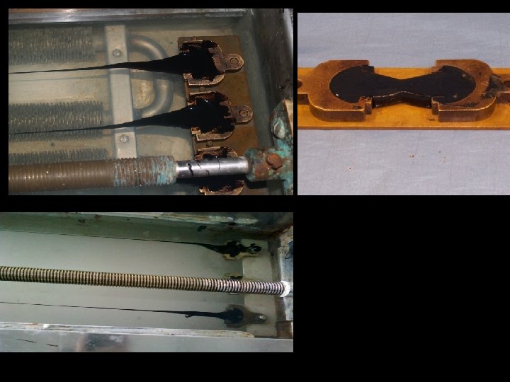
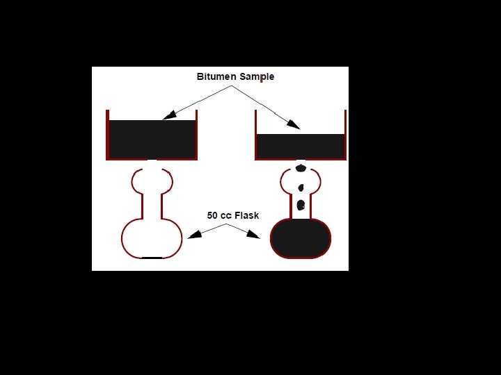
Viscosity test Viscosity denotes the fluid property of bituminous material and it is a measure of resistance to flow. At the application temperature, this characteristic greatly influences the strength of resulting paving mixes. Low or high viscosity during compaction or mixing has been observed to result in lower stability values. At high viscosity, it resist the compactive effort and thereby resulting mix is heterogeneous, hence low stability values. And at low viscosity instead of providing a uniform lm over aggregates, it will lubricate the aggregate particles. Orifice type viscometers are used to indirectly find the viscosity of liquid binders like cutbacks and emulsions. The viscosity expressed in seconds is the time taken by the 50 ml bitumen material to pass through the orifice of a cup, under standard test conditions and specified temperature. Viscosity of a cutback can be measured with either 4. 0 mm orifice at 25 o C or 10 mm orifice at 25 or 40 o C.

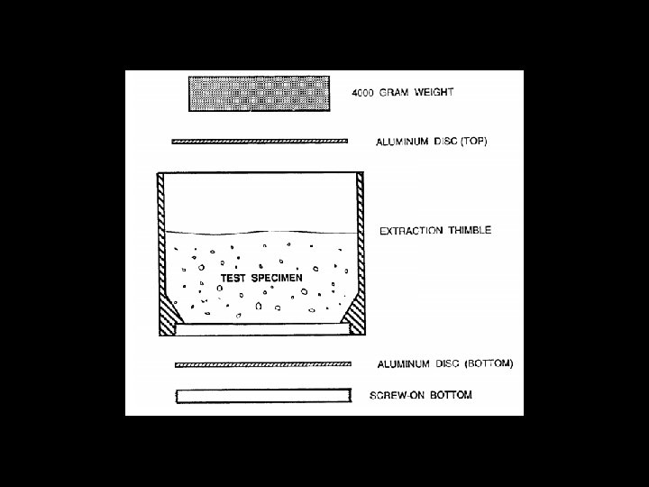
BINDER CONTENT For each group of 3 of the 1500 g samples having the same binder content, heat the aggregate and the asphalt binder to 275°F ± 9°F. 2. Place an aluminum disc in the bottom of each extraction thimble and attach the screw-on bottom so that the aluminum disc is firmly held in place. 3. Tare each extraction thimble with the bottom disc assembly in place. 4. Preheat 3 extraction thimble assemblies, 3 top discs and 3 cylindrical steel blocks in an oven at 275°F ± 9°F for a minimum of 15 min. 5. Mechanically mix or hand mix the 3 individual samples of aggregate and asphalt binder for 2 min ± 5 s. Mix over a heat source such as an infrared lamp or a hot plate to avoid loss of temperature.

6. After mixing, immediately transfer each mix into a heated extraction thimble assembly. Use a spatula to scrape clean the insides of the mixing bowl or pan. 7. Place an aluminum disc on top of each mix (Figure 1). 8. Place a cylindrical steel block on top of each disc (Figure 1). 9. Place each of the 3 assembled samples into an oven maintained at a temperature of 275°F ± 9°F for 30 min ± 15 s. 10. Remove the sample from the oven, remove the cylindrical steel block and top disc, invert the thimble, and dump the test specimen into a pan. Tap the bottom of the thimble assembly 10 times with the spatula handle to dislodge any loose material. Remove aggregate particles larger than No. 8 from the thimble assembly. 11. Allow the thimble and bottom disc assembly to cool to room temperature for a minimum of 20 min. 12. Reweigh each thimble with the bottom disc assembly in place to determine grams of asphalt drainage

CONSTRUCTION PRACTICE Excavation WATER BOUND MACADAM ROAD The box cutting shall be done in such a way, that the width of cutting is exactly that of the sub-base width. The depth of cutting shall be total thickness of sub-base, consolidated soling, road metalling and bituminous wearing course. The formation shall have the same profile and camber as shown on the drawings. Preparation of the Subgrade After the box cutting is completed the formation shall be watered and rolled to a proper gradient and camber with a road roller of 8 to 10 tonnes weight minimum, for thorough compaction, care shall be taken to avoid excessive rolling of the formation.

Preparation of the Sub-base After rolling of the subgrade is completed, the granular sub-base material shall be laid in two separate layers of 150 mm and 200 mm respectively and consecutively or as specified in the drawing and as instructed by Engineer In Charge. The first layer of 150 mm, shall be laid over the compacted subgrade between the edges of box-cutting, watered and rolled to a proper gradient and camber with a road roller of 8 tonnes weight minimum for thorough compaction to achieve a CBR value greater than 20%. Subsequently the second layer of 200 mm shall also be laid over the first layer, watered and rolled to a proper gradient and camber with 8 tonnes road roller and thoroughly compacted with a CBR valve of 10% is achieved. Excessive rolling shall be avoided.

Base Course The stones shall be laid closely packed to the profile of the finished road surface in such a way that these shall not move under pressure. A thin cushion of murrum shall be placed over the sub-base and packed with the stone. The joints shall preferably be staggered. Soling shall commence from edges and proceed towards the center. The profile of the soling shall frequently be checked with templates as the laying progresses. When a sufficient length of soling has been laid this shall be watered and packed with a power road roller of not less than 8 tonnes capacity and the surface shall be evened by blinding with small pieces of stone and chipping during rolling. A final thin cushioning with murrum shall be spread over the surface and watered and lightly rolled. Rolling shall be continued till the required compacted thickness is obtained

wearing course Road metal from road side stacks shall be raked on to the carriage way soling course directly. Spreading shall be done to the specified camber and thickness, but never more than 100 mm at a time to make a consolidated thickness of at least 75 mm after rolling. Two such layers shall be spread and consolidated separately but consequently to form a total compacted thickness of 150 mm. The surface so laid in each layer shall be checked up by means of wooden templates and spirit levels placed every 6 to 7 meters, the top surface being dressed up and hand packed with smaller pieces of stone between successive templates. Transition strips and curves shall be checked up very carefully

Dry-Rolling When spreading has been done for a sufficient length (not less than 15 M) and checked up with templates, dry rolling shall be started with a power road roller of 8 tonnes minimum weight, to obtain perfect inter locking of the adjacent pieces of stones. Adding Screenings When the desired degree of compaction has been obtained by dry rolling screenings of approved stone chippings shall be spread uniformly over the surface by brooming and these shall be pushed into the interstices by rolling, successive layers of screenings being added till no more chippings are taken up by the surface. Any unevenness observed shall be rectified by removing stones to a depth of 50 to 75 mm, refilling the same, hand packing and re-rolling. No watering shall be done till the process is complete.

Spreading of blindage and wet rolling Approved quality blindage such as murrum or sandy loam shall then be spread uniformly over the surface to a thickness of about 12 mm, copiously watered and rolled. The roller wheels as well as the road surface shall be constantly watered during the wet rolling and nay stone piece picked up shall be replaced by hand. The rolling shall be continued until a slurry is formed over the entire surface and the same moves in a wave in front of the roller wheels as it moves, when rolling may be stopped and the surface allowed to dry. The finished surface shall be smooth and uniform, free from waviness and corrugations and as per specified profile and camber.

Finishing, curing and opening up the road to traffic After 24 hours of wet rolling, the surface shall be covered with a thin layer of sand (about 12 mm thick) for curing. Ordinarily the newly consolidated surface shall not be opened to traffic till it is dry which may take 2 to 4 days depending on weather conditions. As the surface dries up the road maybe opened to traffic

BITUMINOUS ROAD Preparation of Existing Water Bound Macadam Surface: The existing water bound macadam surface shall be brushed, cleaned properly with wire brushes and coir brooms, so as to free from all loose materials, murrum, earth, silt and caked mud etc. If during the process of cleaning the sub grade (water bound macadam), soft spots and pockets, hollows etc. are found, such spots/pockets will be filled with approved precoated bituminous chips, consolidated and finished to proper level, rolled with power roller if necessary. The pot holes shall be excavated properly in a rectangular or rhomboidal shape with vertical edges. The bottom and sides shall be cleaned as stated above. The sides and bottom shall then be thoroughly painted with heated 80/100 penetration bitumen. The pot hole shall thereafter be filled with premixed bituminous chips so that after thorough tamping and rolling, the surface is flush with surrounding road surface.

HOT MIXED HOTLAID BITUMINOUS ROAD: Tack Coat: Bitumen of the grade as specified in the Schedule of Quantities shall be heated to a temperature of 1630 C to 1770 C (3250 F to 3500 F) in a bitumen boiler and the hot bitumen shall be applied evenly to the thoroughly cleaned and prepared road surface (as specified here-in-before) @ 8. 5 kg. per 10 sqm. Leaving no part of the surface unpainted. Application shall be done by a mechanical pressure sprayer or if permitted, by perforated pouring cans. The tack coat shall be applied just before the macadam is laid. Application of tack coat shall be only slightly in advance of laying premixed chips. In case of surface already asphalted application of tack coat is not necessary.

Compaction : The base bituminous macadam course shall be compacted thoroughly and evenly with 8 to 10 tonne power roller immediately after it is laid. Compacted thickness shall be as specified in schedule of quantity. The surface shall be checked for correct grade during and after rolling. Any irregularities shall be corrected by adding precoated chips or removing the surplus. The disturbed surface shall be well compacted again. If necessary, the roller wheel shall be coated with oil to prevent the coated chip from sticking to the wheels. Rolling shall be continued till no wheel marks are left on the surface.

CONCRETE ROAD Preparing the grade, or roadbed Subgrade: earth that has been graded to the desired elevation. (In county and municipal paving projects with low traffic volumes, concrete is often placed directly on the prepared earth subgrade. ) Subbase: a course of material that is placed on the subgrade to provide drainage and stability. Granular subbase is the most drainable subbase. It is a mixture of granular material that is uniformly shaped and minimally compacted. It does not provide significant structural support; no construction traffic is allowed on a granular subbase.

Placing dowel bars Dowel bars transfer heavy loads across joints in the pavement, preventing faulting at the joint that can lead to pavement damage. Practices vary from state to state, but dowel bars are typically required in eight-inch or thicker pavements. Dowels must be positioned and aligned perfectly so that, as joints open in winter and close in summer with contraction and expansion of the concrete, the pavement on either side of the joints can move in a straight line along the smooth dowels.

Wetting the grade: A dry subbase draws water from the bottom of the concrete mixture. This can produce stress due to differential moisture levels throughout the slab, causing cracking. To help prevent these stresses, thoroughly spray the subbase with water shortly before Placing the concrete: Delivering the mix when transporting the mixture from plant to construction site, the goal is to deliver well mixed, workable concrete to the construction site. It is essential that the mixture be uniform and consistent from batch to batch.

Placing the concrete To prevent differential compaction that can interfere with good drainage, haul trucks should not be driven on the subbase. If the grade provides adequate space, delivery vehicles should deliver the concrete from a haul road adjacent to the area to be paved. The mix is deposited, from off the grade, in front of the paver. It may be deposited by a belt placer or other method. Setting header joints Header joints are built at the end of a section of pavement where, in the future, pavement construction will continue. Header joints must be constructed at the end of a pour or a day’s run, or if paving is delayed by 30 minutes or more.

Header construction 1. A header board is placed just beyond the line where the paver has pulled away from the slab. 2. Tie-bars protruding through the header board are placed into the fresh concrete and stick out beyond the board. (The protruding ends will be incorporated into the next pavement section. ) 3. The header area is hand-poured, then vibrated, finished, and cured. Concrete should be well consolidated against the header board and finished with an edging tool. Placing tie-bars during construction When two or more lanes are placed, tie-bars must be placed across the centerline or lane lines to prevent movement along the line. If the paver does not install tie bars mechanically, a crew member rides on the paver and inserts them manually. In either case, a timing device —usually a wheel of a specific circumference riding on the paver track—is used to ensure the correct spacing.

Finishing Immediately after the paver passes, the surface is normally finished to close holes and create a tight surface. Crews standing along the slab edge run finishing tools (floats and straightedges) across the surface. Curing The importance of managing moisture in concrete immediately after placement cannot be overemphasized. Concrete moisture is managed primarily through proper curing—that is, by applying curing compound uniformly to the entire surface and exposed edges of the concrete to slow the evaporation of water from the concrete. Curing preserves water for hydration, maximizing pavement strength and durability. It also helps prevent the surface from drying out more quickly than the rest of the slab, reducing the possibility of surface damage due to differential shrinkage.
- Slides: 54