UNIT3 HYDRAULIC SIMILTUDE BACKGROUND Although many practical engineering

UNIT-3: HYDRAULIC SIMILTUDE

BACKGROUND Although many practical engineering problems involving fluid mechanics can be solved by • Equations and Analytical procedures yet a large number of problems rely on experimental data for their solution In fact, very few problems involving real fluids can be solved by analytical analysis alone In general, solution is obtained through the use of a combination of analysis and experimental data An obvious goal of any experiment is to make the results as widely applicable as possible To achieve this goal, the concept of similitude is often used so that measurements made on one system (Laboratory) can be used to describe the behavior of other systems (Outside of laboratory) 2

BACKGROUND The laboratory systems are usually thought of as models and are used to study the phenomenon of interest under carefully controlled conditions From these model studies, empirical formulations can be developed, or specific predictions of one or more characteristics of some other similar system can be made However, to do this, it is necessary to establish the relationship between the laboratory model and the “other” system In present topic, we will learn how to achieve this in a systematic manner 3

BACKGROUND Sudden contraction in pipes Wind turbine Dam/spillway Dimensional Analysis to predict the physical parameters that will significantly influence phenomenon under study Similitude and Model analysis to investigate the complexity of phenomenon in details Application of knowledge on actual/prototype model 4

DIMENSIONAL ANALYSIS Introduction: Dimensional Analysis is a mathematical technique making use of study of dimensions It deals with the dimensions of physical quantities involved in the phenomenon In dimensional analysis, one first predicts the physical parameters that will influence the flow, and then by, grouping these parameters in dimensionless combinations a better understanding of the flow phenomenon is made possible It is particularly helpful in experimental work because it provides a guide to those things that significantly influence the phenomena; thus it indicates the direction in which the experimental work should go This mathematical technique is used in research work for design and for conducting model tests 5

TYPES OF DIMENSIONS There are two types of dimensions • Fundamental Dimensions or Fundamental Quantities • Secondary Dimensions or Derived Quantities Fundamental Dimensions or Fundamental Quantities: These are basic quantities. For Example; • Time, T • Distance, L • Mass, M Time, T Distance, L, Force, F Force=Mass x Acceleration = MLT-2 6

TYPES OF DIMENSIONS Secondary Dimensions or Derived Quantities The are those quantities which posses more than one fundamental dimensions. For example; • Velocity is denoted by distance per unit time L/T • Acceleration is denoted by distance per unit time square L/T 2 • Density is denoted by mass per unit volume M/L 3 Since velocity, density and acceleration involve more than one fundamental quantities so these are called derived quantities. 7
 Dimension (MLT)")
Table: Flow Characteristics, units and Dimensions Characteristics Geometry Kinematic Dynamic Unit (SI) Dimension (MLT) Dimension (FLT) Length m L Area m 2 L 2 Volume m 3 L 3 Time S T Velocity m/S L/T Acceleration m/S 2 L/T 2 Discharge m 3/S L 3/T Mass Kg M FL-1 T 2 Force N (Kg-m/S 2) MLT-2 F Pressure Pa (N/m 2) ML-1 T-2 FL-2 Energy J (N-m) ML 2 T-2 FL Power Watt (N-m/S) ML 2 T-3 FLT-1 8

METHODOLOGY OF DIMENSIONAL ANALYSIS The basic principle is Dimensional Homogeneity, which means the dimensions of each terms in an equation on both sides are equal. So such an equation, in which dimensions of each term on both sides of equation are same, is known as Dimensionally Homogeneous Equation. Such equations are independent of system of units. For example; Lets consider the equation V=(2 g. H)1/2 • Dimensions of LHS=V=L/T=LT-1 • Dimensions of RHS=(2 g. H)1/2=(L/T 2 x. L)1/2=LT-1 • Dimensions of LHS = Dimensions of RHS So the equation V=(2 g. H)1/2 is dimensionally homogeneous equation. 9

METHODS OF DIMENSIONAL ANALYSIS If the number of variables involved in a physical phenomenon are known, then the relation among the variables can be determined by the following two methods; • Rayleigh’s Method • Buckingham’s π-Theorem Rayleigh’s Method: It is used for determining expression for a variable (dependent) which depends upon maximum three to four variables (Independent) only. If the number of independent variables are more than 4 then it is very difficult to obtain expression for dependent variable. Let X is a dependent variable which depends upon X 1, X 2, and X 3 as independent variables. Then according to Rayleigh’s Method X=f(X 1, X 2, X 3) X=K X 1 a, X 2 b, X 3 c which can be written as Where K is a non-dimensional constant and a, b, c are arbitrary powers which are obtained by comparing the powers of fundamental dimensions (Dimensional Homogeneity). 10

RAYLEIGH’S METHOD Q. The resisting force R of a supersonic plane during flight can be considered as dependent upon the length of the aircraft l, velocity V, air viscosity µ, air density ρ, and bulk modulus of air k. Express the functional relationship between the variables and the resisting force. Solution: R f (l, V , , , K ) R Al a , V b , c , d , K e (1) Where: A = Non dimensional constant Substituting the powers on both sides of the equation MLT -2 ALa (LT 1)b (ML 1 T 1)c (ML 3 )d (ML 1 T 2 )e Equating the powers of MLT on both sides Power of M 1 c d e Power of L 1 a b - c - 3 d - e Power of T 2 -b - c - 2 e 11
 are more than number of equations(3). So expressing a,")
RAYLEIGH’S METHOD Since the unkown(5) are more than number of equations(3). So expressing a, b & c in terms of d & e d 1 - c - e b 2 - c - 2 e a 1 - b c 3 d e 1 - (2 - c - 2 e) c 3(1 - c - e) e 1 - 2 c 2 e c 3 - 3 c - 3 e e 2 - c Substituting the values in (1), we get R Al 2 c. V 2 c 2 e c 1 c e K e Al 2 V 2 (l c. V c c c )(V 2 e e K e ) e c K R A l 2 V 2 2 Vl V K R A l V 2 Vl V 2 OR 2 12

RAYLEIGH’S METHOD u f K , u C Ka, b 13

RAYLEIGH’S METHOD 14

RAYLEIGH’S METHOD 15

BUCKINGHAM’S Π-THEOREM: Buckingham’s π-Theorem: Since Rayleigh’s Method becomes laborious if variables are more than fundamental dimensions (MLT), so the difficulty is overcome by Buckingham’s π-Theorem which states that “If there are n variables (Independent and Dependent) in a physical phenomenon and if these variables contain m fundamental dimensions then the variables are arranged into (n-m) dimensionless terms which are called π-terms. ” Let X 1, X 2, X 3, …, X 4, Xn are the variables involved in a physical problem. Let X 1 be the dependent variable and X 2, X 3, X 4, …, Xn are the independent variables on which X 1 depends. Mathematically it can be written as X 1=f(X 2 , X 3 , X 4 , Xn) f(X 1 X 2 , X 3 , X 4 , Xn)=0 which can be rewritten as Above equation is dimensionally homogenous. It contain n variables and if there are m fundamental dimensions then it can be written in terms of dimensions groups called π-terms which are equal to (n-m) Hence; f(π1, π2 π3, … πn-m)=0 16

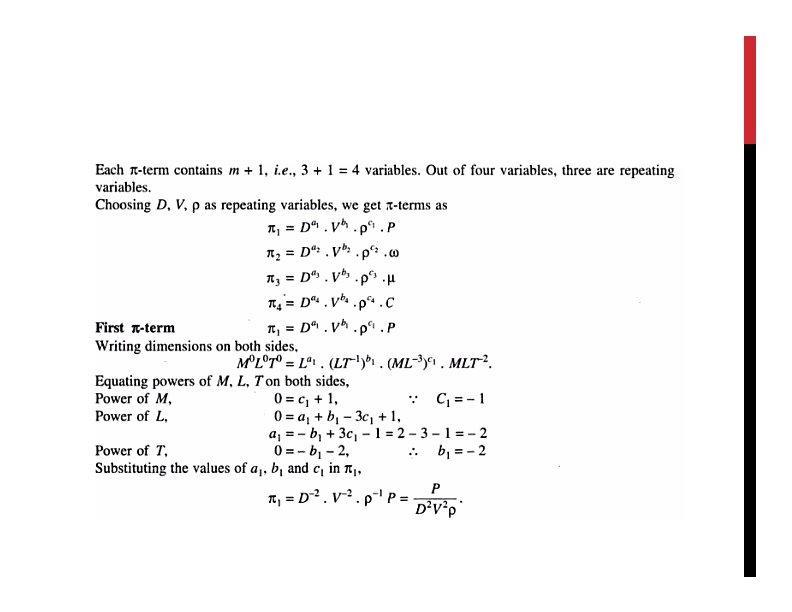
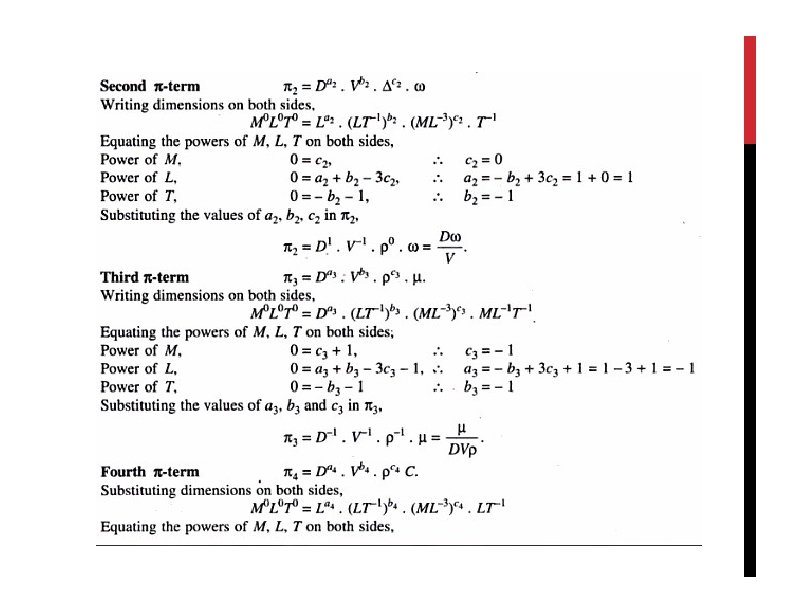
BUCKINGHAM’S Π-THEOREM: Properties of π-terms: • Each π-term is dimensionless and is independent of system of units. • Division or multiplication by a constant does not change the character of the π-terms. • Each π-term contains m+1 variables, where m is the number of fundamental dimensions and also called repeating variable. Let in the above case X 2, X 3, X 4 are repeating variables and if fundamental dimensions m = 3 then each π-term is written as Π 1=X 2 a 1. X 3 b 1. X 4 c 1. X 1 Π 2=X 2 a 2. X 3 b 2. X 4 c 2. X 5. . Πn-m=X 2 a(n-m). X 3 b(n-m). X 4 a(n-m). Xn Each equation is solved by principle of dimensionless homogeneity and values of a 1, b 1 & c 1 etc are obtained. Final result is in the form of Π 1=ϕ’(Π 2, Π 3, Π 4 , …, Π(n-m)) Π 2=ϕ”(Π 1, Π 3, Π 4 , …, Π(n-m)) 17

METHODS OF SELECTING REPEATING VARIABLES The number of repeating variables are equal to number of fundamental dimensions of the problem. The choice of repeating variables is governed by following considerations; • As far as possible, dependent variable should not be selected as repeating variable • The repeating variables should be chosen in such a way that one variable contains geometric property, other contains flow property and third contains fluid property • The repeating variables selected should form a dimensionless group • The repeating variables together must contain all three fundamental dimension i. e. , MLT • No two repeating variables should have the same dimensions. Note: In most of fluid mechanics problems, the choice of repeating variables may be (i) d, v, ρ, (ii) l, v, ρ or (iii) d, v, µ. 18

BUCKINGHAM’S Π-THEOREM: Q 1. The resisting force R of a supersonic plane during flight can be considered as dependent upon the length of the aircraft l, velocity V, air viscosity µ, air density ρ, and bulk modulus of air k. Express the functional relationship between the variables and the resisting force. R f (l, V , , , K ) f (R, l, V , , , K ) 0 Total number of variables, n= 6 No. of fundamental dimension, m=3 No. of dimensionless -terms, n-m=3 Thus: f ( 1, 2 , 3 ) 0 No. Repeating variables =m=3 Repeating variables =l, V , Thus π-terms are written as 1 la 1 V b 1 c 1 R 2 la 2 V b 2 c 2 a 3 b 3 c 3 3 l V K 19

BUCKINGHAM’S Π-THEOREM: Now each Pi-term is solved by the principle of dimensional homogeneity 1 term M o Lo. T o La 1 (LT 1 )b 1 (ML 3 )c 1 MLT 2 Equating the powers of MLT on both sides, we get Power of M: 0=c 1 +1 c 1 =-1 Power of L: 0=a 1 +b 1 -3 c 1 +1 a 1 2 Power of T: 0=-b 1 -2 b 1 =-2 R L 2 V 2 2 term M o Lo. T o La 2 (LT 1 )b 2 (ML 3 )c 2 ML 1 T 1 1 l-2 V -2 -2 R 1 Equating the powers of MLT on both sides, we get Power of M: 0 c 2 1 c 2 -1 Power of L: 0 a 2 b 2 - 3 c 2 -1 a 2 1 Power of T: 0 -b 2 -1 b 2 -1 2 l-1 V -1 -1 2 l. V 20
b")
BUCKINGHAM’S Π-THEOREM: 3 term M o Lo. T o La 3 (LT 1 )b 3 (ML 3 ) c 3 ML 1 T 2 Equating the powers of MLT on both sides, we get Power of M: 0 c 3 1 c 3 -1 Power of L: 0 a 3 b 3 - 3 c 3 -1 a 3 0 Power of T: 0 -b 3 - 2 b 3 -2 3 l 0 V -2 -1 K 2 K V 2 Hence R K f ( 1 2 3 ) f 2 2 , , 2 0 or l V l. V V R K K 2 2 , 2 R l V , 2 2 2 l V l. V V 21

BUCKINGHAM’S Π-THEOREM: Q 2. A thin rectangular plate having a width, w, and height, h, is located so that it is normal to a moving stream of fluid. Assume the drag D, that the fluid exerts on the plate is a function of w and h, the fluid viscosity and density µ, and ρ, respectively, and velocity V of the fluid approaching the plate. Determine a suitable set of pi terms to study this problem experimentally From the statement of problem, we can write: D f w, h, , , V Total number of variables, n 6 No. of fundamental dimension, m 3 No. of pi terms, n - m 6 - 3 3 Repeating variables w, , V The dimension of variables using MLT system are D MLT -2 , w L, h L ML 1 T 1 V LT 1 22

BUCKINGHAM’S Π-THEOREM: Now the pi terms can be written as a 1 b 1 c 1 a 2 b 2 c 2 a 3 b 3 1 Dw V , 2 hw V , 3 w V c 3 For 1 : a 1 b 1 1 Dw V c 1 M 0 L 0 T 0 MLT 2 L a 1 LT 1 For M : 0 1 c 1 For L : 0 1 a 1 b 1 - 3 c 1 ML b 1 3 c 1 For T : 0 -2 - b 1 Therefore, a 1 -2, b 1 -2 and c 1 -1 2 2 1 Dw V D 1 2 2 w. V 1 23

BUCKINGHAM’S Π-THEOREM: Now the pi terms can be written as a 1 b 1 c 1 a 2 b 2 c 2 a 3 b 3 1 Dw V , 2 hw V , 3 w V c 3 For 2 : a 2 b 2 2 hw V c 2 M 0 L 0 T 0 L L a 2 LT 1 ML 3 For M : 0 c 2 For L : 0 1 a 2 b 2 - 3 c 2 b 2 c 2 For T : 0 -b 2 Therefore, a 2 -1, b 2 0 and c 2 0 1 0 2 hw V 2 0 h w 24

BUCKINGHAM’S Π-THEOREM: Now the pi terms can be written as a 1 b 1 c 1 a 3 b 3 1 Dw V , 2 hw V , 3 w V For 3 : a 3 b 3 c 3 3 w V a 2 M 0 L 0 T 0 ML 1 T 1 L a 3 LT 1 For M : 0 1 c 3 b 2 c 3 ML b 3 3 c 3 For L : 0 1 a 3 b 3 - 3 c 3 For T : 0 -1 - b 3 Therefore, a 3 1, b 3 1 and c 3 -1 1 1 3 w V 3 � w. V 1 25

BUCKINGHAM’S Π-THEOREM: Finally the results of dimensional analysis can be represented in the form 1, 2 , 3 , 4 , . . . , n m 0 1 2 , 3 , 4 , . . . , n m w D , 2 2 w. V h w. V 26

BUCKINGHAM’S Π-THEOREM: Let’s solve it now 27

BUCKINGHAM’S Π-THEOREM: Let’s solve it now 28

BUCKINGHAM’S Π-THEOREM: 31

For more worked problems refer to Civil Engineering Hydraulics by Nalluri and Featherstone (Worked problems 9. 1 to 9. 11)

SIMILITUDE AND MODEL ANALYSIS Similitude is a concept used in testing of Engineering Models. Usually, it is impossible to obtain a pure theoretical solution of hydraulic phenomenon. Therefore, experimental investigations are often performed on small scale models, called model analysis. A few examples, where models may be used are ships in towing basins, air planes in wind tunnel, hydraulic turbines, centrifugal pumps, spillways of dams, river channels etc and to study such phenomenon as the action of waves and tides on beaches, soil erosion, and transportation of sediment etc. 33

MODEL ANALYSIS Model: is a small scale replica of the actual structure Prototype: the actual structure or machine Lp 1 Lp 2 Lm 1 Lm 2 Fp 1 Fp 2 Fp 3 Lp 3 Prototype Fm 1 Fm 2 Fm 3 Lm 3 Model Note: It is not necessary that the models should be smaller that the prototype, they may be larger than prototype 34

MODEL ANALYSIS Model Analysis is actually an experimental method of finding solutions of complex flow problems The followings are the advantages of the model analysis • Using dimensional analysis, a relationship between the variables influencing a flow problem is obtained which help in conducting tests • The performance of the hydraulic structure can be predicted in advance from its model • The merits of alternative design can be predicted with the help of model analysis to adopt most economical, and safe design Note: Test performed on models can be utilized for obtaining, in advance, useful information about the performance of the prototype only if a complete similarity exits between the model and the prototype 35

SIMILITUDE-TYPE OF SIMILARITIES Similitude: is defined as similarity between the model and prototype in every respect, which mean model and prototype have similar properties or model and prototype are completely similar. Three types of similarities must exist between model and prototype. • Geometric Similarity • Kinematic Similarity • Dynamic Similarity 36

SIMILITUDE-TYPE OF SIMILARITIES Geometric Similarity: is the similarity of shape. It is said to exist between model and prototype if ratio of all the corresponding linear dimensions in the model and prototype are equal. e. g. Lp Lm Bp Bm Dp Dm Lr Where: Lp, Bp and Dp are Length, Breadth, and diameter of prototype and Lm, Bm, Dm are Length, Breadth, and diameter of model. Lr= Scale ratio Note: Models are generally prepared with same scale ratios in every direction. Such models are called true models. However, sometimes it is not possible to do so and different convenient scales are used in different directions. Thus, such models are called distorted model 37

SIMILITUDE-TYPE OF SIMILARITIES Kinematic Similarity: is the similarity of motion. It is said to exist between model and prototype if ratio of velocities and acceleration at the corresponding points in the model and prototype are equal. e. g. Vp 1 Vm 1 Vp 2 Vm 2 Vr ; a p 1 am 1 ap 2 am 2 ar Where: Vp 1& Vp 2 and ap 1 & ap 2 are velocity and accelerations at point 1 & 2 in prototype and Vm 1& Vm 2 and am 1 & am 2 are velocity and accelerations at point 1 & 2 in model. Vr and ar are the velocity ratio and acceleration ratio Note: Since velocity and acceleration are vector quantities, hence not only the ratio of magnitude of velocity and acceleration at the corresponding points in model and prototype should be same; but the direction of velocity and acceleration at the corresponding points in model and prototype should also be parallel. 38

SIMILITUDE-TYPE OF SIMILARITIES Dynamic Similarity: is the similarity of forces. It is said to exist between model and prototype if ratio of forces at the corresponding points in the model and prototype are equal. e. g. Fi p Fv p Fi m Fv m F F g p Fr g m Where: (Fi)p, (Fv)p and (Fg)p are inertia, viscous and gravitational forces in prototype and (Fi)m, (Fv)m and (Fg)m are inertia, viscous and gravitational forces in model. Fr is the Force ratio Note: The direction of forces at the corresponding points in model and prototype should also be parallel. 39

TYPES OF FORCES ENCOUNTERED IN FLUID PHENOMENON Inertia Force, Fi: It is equal to product of mass and acceleration in the flowing fluid. Viscous Force, Fv: It is equal to the product of shear stress due to viscosity and surface area of flow. Gravity Force, Fg: It is equal to product of mass and acceleration due to gravity. Pressure Force, Fp: it is equal to product of pressure intensity and cross-sectional area of flowing fluid. Surface Tension Force, Fs: It is equal to product of surface tension and length of surface of flowing fluid. Elastic Force, Fe: It is equal to product of elastic stress and area of flowing fluid. 40

DIMENSIONLESS NUMBERS Dimensionless numbers are the numbers which are obtained by dividing the inertia force by viscous force or gravity force or pressure force or surface tension force or elastic force. As this is ratio of once force to other, it will be a dimensionless number. These are also called nondimensional parameters. The following are most important dimensionless numbers. • Reynold’s Number • Froude’s Number • Euler’s Number • Weber’s Number • Mach’s Number 41

DIMENSIONLESS NUMBERS Reynold’s Number, Re: It is the ratio of inertia force to the viscous force of flowing fluid. Velocity Volume. Velocity Fi Time Re Fv Shear Stress. Area Mass. Q. V AV. V VL . A du. A V. A dy L Froude’s Number, Fe: It is the ratio of inertia force to the gravity force of flowing fluid. Fe Fi Fg Velocity Time Mass. Gavitational Acceleraion Mass. Volume. Velocity Time Mass. Gavitational Acceleraion V 2 AV. V V AL. g g. L Volume. g g. L Q. V 42

DIMENSIONLESS NUMBERS Eulers’s Number, Eu: It is the ratio of inertia force to the pressure force of flowing fluid. Fi Fp Eu Q. V P. A Velocity Time Pr essure. Area Volume. Velocity Mass. AV. V P. A V 2 P / Time Pr essure. Area V P / Weber’s Number, We: It is the ratio of inertia force to the surface tension force of flowing fluid. We Fi Fg Velocity Time Surface Tensionper. Length Mass. Volume. Velocity Time Surface Tensionper. Length AV. V L 2 V 2 V Q. V . L . L L 43

DIMENSIONLESS NUMBERS Mach’s Number, M: It is the ratio of inertia force to the elastic force of flowing fluid. M Fi Fe Q. V K. A Velocity Time Elastic Stress. Area Time Elastic Stress. Area AV. V V Mass. K. A L 2 V 2 KL 2 Volume. Velocity K/ V C Where : C K / 44

MODEL LAWS OR SIMILARITY LAWS We have already learned that for dynamic similarity, ratio of corresponding forces acting on prototype and model should be equal i. e. Fv p Fg p Fp p Fs p Fe p FI p Fv m Fg m Fp m Fs m Fe m FI m Force of inertial comes in play when sum of all other forces is not equal to zero which mean: F F v g Fp Fs Fe FI Thus dynamic similarity require that F F v Fg Fp Fs Fe v Fg Fp FI p Fs Fe FI m m p In case all the forces are equally important, the above two equations cannot be satisfied for model analysis 45

MODEL LAWS OR SIMILARITY LAWS However, for practical problems it is seen that one force is most significant compared to others and is called predominant force or most significant force. Thus, for practical problem only the most significant force is considered for dynamic similarity. Hence, models are designed on the basis of ratio of force, which is dominating in the phenomenon. Finally, the laws on which models are designed for dynamic similarity are called models laws or laws of similarity. The followings are these laws • • • Reynold’s Model Law Froude’s Model Law Euler’s Model Law Weber’s Model Law Mach’s Model Law 46

REYNOLD’S MODEL LAW It is based on Reynold’s number and states that Reynold’s number for model must be equal to the Reynolds number for prototype. Reynolds Model Law is used in problems where viscous forces are dominant. These problems include: • Pipe Flow • Resistance experienced by submarines, airplanes, fully immersed bodies etc Re P Re m or VP LP P Vm. Lm m VP LP VL r r 1 P r Vm Lm m VP LP P where : Vr , Lr , r Vm Lm m 47

REYNOLD’S MODEL LAW The Various Ratios for Reynolds’s Law are obtained as VL and / sin ce P m VP Lm P = r Velocity Ratio: Vr Vm LP m L r Time Ratio: Tr= TP LP /VP Lr Tm Lm /Vm Vr a. P VP / TP Vr Acceleration Ratio: a r= am Vm / Tm Tr Discharge Ratio: Q r APVP L 2 r. Vr Am. Vm 2 2 2 Force Ratio: F =mr a r Q r Vr r Lr Vr rr Power Ratio: P =F. V = L 2 V 2 V L 2 V 3 r r r r r 48

REYNOLD’S MODEL LAW Q. A pipe of diameter 1. 5 m is required to transport an oil of specific gravity 0. 90 and viscosity 3 x 10 -2 poise at the rate of 3000 litre/s. Tests were conducted on a 15 cm diameter pipe using water at 20 o. C. Find the velocity and rate of flow in the model. Solution: Prototype Data: Diameter, Dp= 1. 5 m Viscosity of fluid, µp= 3 x 10 -2 poise Discharge, Qp =3000 litre/sec Sp. Gr. , Sp=0. 9 Density of oil=ρp=0. 9 x 1000 =900 kg/m 3 Model Data: Diameter, Dm=15 cm =0. 15 m Viscosity of water, µm =1 x 10 -2 poise Density of water, ρm=1000 kg/m 3 Velocity of flow Vm=? Discharge Qm=? For pipe flow, According to Reynolds' Model Law m. Vm. Dm p. Vp. Dp Vm p. Dp m V p m D m p m p Vm 900 1. 5 1 10 2 3. 0 2 V p 1000 0. 15 3 10 Since Vp Qp Ap 3. 0 / 4(1. 5)2 1. 697 m / s Vm 3. 0 Vp 5. 091 m / s and Q V A 5. 091 / 4(0. 15)2 m m m 0. 0899 m 3 / s 49

REYNOLD’S MODEL LAW Q. A ship 300 m long moves in sea water, whose density is 1030 kg/m 3. A 1: 100 model of this ship is to be tested in a wind tunnel. The velocity of air in the wind tunnel around the model is 30 m/s and the resistance of the model is 60 N. Determine the velocity of ship in sea water and also the resistance of ship in sea water. The density of air is given as 1. 24 kg/m 3. Take the kinematic viscosity of air and sea water as 0. 012 stokes and 0. 018 stokes respectively. Solution: For Prototype Length, Lp= 300 m Fluid = sea water Density of sea water, ρp= 1030 kg/m 3 Kinematic Viscosity, νp=0. 018 stokes =0. 018 x 10 -4 m 2/s Let Velocity of ship, Vp Resistance, Fp For Model Scale ratio = Lp/Lm=100 Length, Lm= Lp/100 = 3 m Fluid = air Density of air, ρm=1. 24 kg/m 3 Kinematic Viscosity, νm=0. 012 stokes =0. 012 x 10 -4 m 2/s Velocity of ship, Vm=30 m/s Resistance, Fm = 60 N 50

REYNOLD’S MODEL LAW For dynamic similarity between model and prototype, the Reynolds number for both of them should be equal. p Lm V VL Vp m L p m m p 0. 018 10 4 3 0. 012 30 0. 2 m / s Vp 4 0. 018 10 300 0. 012 Since Resistance= Mass Acceleration= L 2 V 2 Thus Fp Fm L V � L V 2 2 p m 1030 300 2 0. 2 2 369. 17 1. 24 3 30 Fp 369. 17 60 22150. 2 N 51

FROUDE’S MODEL LAW It is based on Froude’s number and states that Froude’s number for model must be equal to the Froude’s number for prototype. Froude’s Model Law is used in problems where gravity forces is only dominant to control flow in addition to inertia force. These problems include: • Free surface flows such as flow over spillways, weirs, sluices, channels etc. • Flow of jet from orifice or nozzle • Waves on surface of fluid • Motion of fluids with different viscosities over one another F e P F e m or VP g P LP Vm Vm VP or g m Lm LP Lm VP V L Vr / Lr 1; where : Vr P , Lr P L Vm Lm P Vm Lm 52

FROUDE’S MODEL LAW The Various Ratios for Reynolds’s Law are obtained as; sin ce V VP m LP Lm V Velocity Ratio: Vr P Vm Time Ratio: Tr= Lp Lm Lr L TP LP /VP r Lr Tm L m /Vm Lr V/T Vr a Acceleration Ratio: a r= P P P am Vm / Tm Tr Discharge Ratio: Q r Lr 1 Lr APVP L 2 r. V r L 2 r Lr L 5 r/ 2 Am. Vm Force Ratio: Fr=mr ar r Qr. Vr r L 2 r. Vr r Lr 2 Vr 2 r L 2 r L r r L 3 r Power Ratio: Pr=Fr. Vr= r. L V V r L 2 2 r r r 2 3 r r 2 r L L 3 r r 7/2 r 53

FROUDE’S MODEL LAW Q 1. In the model test of a spillway the discharge and velocity of flow over the model were 2 m 3/s and 1. 5 m/s respectively. Calculate the velocity and discharge over the prototype which is 36 times the model size. For Discharge Solution: Given that Qp Qm For Model Discharge over model, Qm=2 m 3/sec Velocity over model, Vm = 1. 5 m/sec Linear Scale ratio, Lr =36 For Prototype Discharge over prototype, Qp =? Velocity over prototype Vp=? Lr 36 2. 5 3 Qp 36 2 15552 m / sec For Dynamic Similarity, Froude Model Law is used Vp Vm Lr 36 6 V p 6 1. 5 9 m / sec 54

FROUDE’S MODEL LAW Q 2. The characteristics of the spillway are to be studied by means of a geometrically similar model constructed to a scale of 1: 10. (i) If 28. 3 cumecs, is the maximum rate of flow in prototype, what will be the corresponding flow in model? (i)If 2. 4 m/s, 50 mm and 3. 5 Nm are values of velocity at a point on the spillway, height of hydraulic jump and energy dissipated per second in model, what will be the corresponding velocity, height of hydraulic jump and energy dissipation per second in prototype? Solution: Given that For Model Discharge over model, Qm=? Velocity over model, Vm = 2. 4 m/sec Height of hydraulic jump, Hm =50 mm Energy dissipation per second, Em =3. 5 Nm Linear Scale ratio, Lr =10 For Prototype Discharge over model, Qp=28. 3 m 3/sec Velocity over model, Vp =? Height of hydraulic jump, Hp =? Energy dissipation per second, Ep =? 55

FROUDE’S MODEL LAW For Discharge: For Hydraulic Jump: Qp Hp Qm L 10 2. 5 r 2. 5 Hm Lr 10 Qm 28. 3 /102. 5 0. 0895 m 3 / sec H p 50 10 500 mm For Velocity: For Energy Dissipation: Vp Ep Vm Lr 10 Vp 2. 4 10 7. 589 Em 3. 5 L 3. 5 10 r 3. 5 m / sec E p 3. 5 10 11067. 9 Nm / sec 56

CLASSIFICATION OF MODELS Undistorted or True Models: are those which are geometrically similar to prototype or in other words if the scale ratio for linear dimensions of the model and its prototype is same, the models is called undistorted model. The behavior of prototype can be easily predicted from the results of undistorted or true model. Distorted Models: A model is said to be distorted if it is not geometrically similar to its prototype. For distorted models different scale ratios for linear dimension are used. For example, if for the river, both horizontal and vertical scale ratio are taken to be same, then depth of water in the model of river will be very small which may not be measured accurately. The followings are the advantages of distorted models The vertical dimension of the model can be accurately measured The cost of the model can be reduced Turbulent flow in the model can be maintained Though there are some advantage of distorted models, however the results of such models cannot be directly transferred to prototype. 57

CLASSIFICATION OF MODELS Scale Ratios for Distorted Models Let: L r H Lr V LP BP = Scale ratio for horizontal direction Lm Bm h. P =Scale ratio for vertical direction hm Scale Ratio for Velocity: Vr=VP /V m 2 gh. P 2 ghm Scale Ratio for area of flow: Ar=AP / Am Scale Ratio for discharge: Qr=Q P / Qm Lr V BP h. P Lr H Lr V Bmhm APVP Lr H Lr V Am. Vm Lr V Lr H Lr 3/ 2 V 58

DISTORTED MODEL Q 1. The discharge through a weir is 1. 5 m 3/s. Find the discharge through the model of weir if the horizontal dimensions of the model=1/50 the horizontal dimension of prototype and vertical dimension of model =1/10 the vertical dimension of prototype. Solution: Discharge of River= Q =1. 5 m 3/s p Scale ratio for horizontal direction= Lr H Scale ratio for vertical direction= Lr V LP =50 Lm h. P =10 hm Since Scale Ratio for discharge: Qr=QP / Qm Lr H Lr 3/ 2 V Q / Q 50 103/ 2 1581. 14 p m Qm 1. 5 /1581. 14 0. 000948 m 3 / s 59

DISTORTED MODEL Q 2. A river model is to be constructed to a vertical scale of 1: 50 and a horizontal of 1: 200. At the design flood discharge of 450 m 3/s, the average width and depth of flow are 60 m and 4. 2 m respectively. Determine the corresponding discharge in model and check the Reynolds’ Number of the model flow. 3 Disch arg e of River Qp 450 m / s Width Bp 60 m and Depth y p 4. 2 m BP =200 Bm Horizontal scale ratio= Lr H Vertical scale ratio= Lr V y. P =50 ym Since Scale Ratio for discharge: Qr =QP / Qm Lr H Lr 3/ 2 V Q / Q 200 503/ 2 70710. 7 p m 70710. 7 6. 365 10 3 Qm 450 / 1581. 14 m 3 / s 60

DISTORTED MODEL VL = Reynolds Number, Re m m Lm 4 Rm Width Bm B p / Lr H 60 / 200 0. 3 m Depth ym y p / Lr V 4. 2 / 50 0. 084 m Am Bm ym 0. 3 0. 084 0. 0252 m Pm Bm 2 ym 0. 3 2 0. 084 0. 468 m A 0. 0252 R m 0. 05385 Pm 0. 468 Kinematic Viscosity of water = =1 10 6 m 2 / sec 4 VR 4 0. 253 0. 05385 54492. 31 Re 1 10 6 m >2000 Flow is in turbulent range 61

PROBLEM

DIMENSIONAL ANALYSIS Repeating variables

MODEL ANALYSIS

PROBLEM

DIMENSIONAL ANALYSIS

MODEL ANALYSIS

THANK YOU 68

WORKED PROBLEMS 69

P 1. SAE 30 oil at is pumped through a 3 -ft-diameter pipeline at a rate of 6400 gallon/min. A model of this pipeline is to be designed using a 3 -in. -diameter pipe and water at as the working fluid. To maintain Reynolds number similarity between these two systems, what fluid velocity will be required in the model? For Reynolds number similarity For Model • Pipe diameter=3 in • Fluid=water • Viscosity=1. 21 x 10 -5 ft 2/s For Prototype • Pipe diameter= 3 ft • Liquid=SAE 30 • viscosity=4. 5 x 10 -3 ft 2/s VD m P m D p V p Vm D p m Vm 6. 4 10 2 ft / s Qp 6400 gallon / min 14. 26 ft 3 / s Vp Q p / Ap 14. 26 / / 4 3 2 2. 02 ft / s 70

P 2. Glycerin at 20 o. C flows with a velocity of 4 m/s through a 30 -mm-diameter tube. A model of this system is to be developed using standard air as the model fluid. The air velocity is to be 2 m/s. What tube diameter is required for the model if dynamic similarity is to be maintained between model and prototype? For Model VD m P For Prototype m V p Dp Dm V p m Dm 0. 736 10− 3 m 71

P 3. The drag characteristics of a torpedo are to be studied in a water tunnel using a 1 : 5 scale model. The tunnel operates with freshwater at 20 oc , whereas the prototype torpedo is to be used in seawater at 15. 6 oc. To correctly simulate the behaviour of the prototype moving with a velocity of 30 m/s, what velocity is required in the water tunnel? For Model • Fluid: water • Viscosity@20 o. C =1. 004 x 10 -6 m 2/s • Vm=? For Prototype • Fluid: Sea water • Viscosity@16. 5 o. C=1. 17 x 10 -6 m 2/s • Vp=30 m/s VD m P m � Dp V p Vm D p m Vm 129 m / s 72

P 4. The design of a river model is to be based on Froude number similarity, and a river depth of 3 m is to correspond to a model depth of 100 mm. Under these conditions what is the prototype velocity corresponding to a model velocity of 1. 2 ms? For Model • dm=0. 1 m • Vm=1. 2 m/s For Prototype dp=3 m For Froude No. Similarity V V gd m gd P V p gd p V gd m Vp=? V p 11 m / s 73

P 5. Water flows at a rate of 40 m 3/s through the spillway of a dam which is 65 m wide. A model spillway, having a width of 0. 9 m, is to be constructed and tested in the laboratory. What is the required flowrate in the model? For Model • lm=0. 9 m • Qm? For Prototype • lp= 65 m • Qp=40 m 3/s For Froude number similarity V V gd m gd P V p �pgd � Vm gd m Qp lr dp / d m Qm Ap. VP Am. Vm Qm Q p / l r 2 1/ 2 l r lr 2. 5 Qm 9. 02 10− 4 m 3 / s 74

P 12. The drag characteristics for a newly designed automobile having a maximum characteristic length of 20 ft are to be determined through a model study. The characteristics at both low speed (approximately 20 mph) and high speed (90 mph) are of interest. For a series of projected model tests, an unpressurized wind tunnel that will accommodate a model with a maximum characteristic length of 4 ft is to be used. Determine the range of air velocities that would be required for the wind tunnel if Reynolds number similarity is desired. Are the velocities suitable? Explain. ? VD m P D p m V Vm � p D p m Since the wind tunnel is unpressurized, the air properties will be approximately the same for model and prototype lp 20 Vm Vp V p 5 Vp 4 lm At low speed Vm 5 20 100 mph At high speed Vm 5 90 450 mph At high velocity in wind tunnel, compressibility of the air would start to become an important factor, whereas compressibility is not important for the prototype. Thus velocity required for the model would not be suitable 76

THANK YOU 78
- Slides: 76