UNIT2 IO PORT INTERFACING INTERFACING OF LEDS WITH


 • An Integrated Development Environment (IDE) is software that assists")


 into")


 is used to debug the software of")


 is an oscilloscope")

- Slides: 49
UNIT-2 I/O PORT INTERFACING
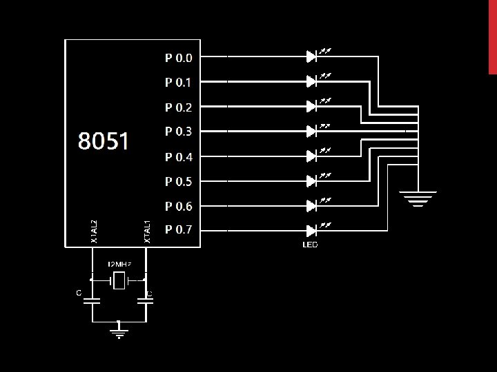
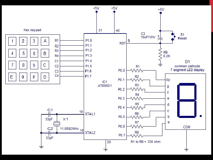
INTERFACING OF LEDS WITH 8051
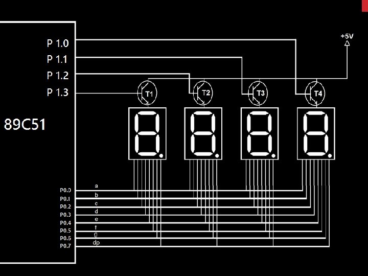
INTERFACING OF 7 -SEGMENT DISPLAY WITH 8051 ΜC
ORG 0000 H MOV P 0, #01111101 B MOV P 1, #00001111 B CALL DELAY MOV P 0, #00000111 B MOV P 0, #0000 B CALL DELAY START: MOV P 0, #01111111 B MOV P 0, #00111111 B ; DISPLAY 0 MOV P 0, #00000110 B ; DISPLAY 1 CALL DELAY MOV P 0, #01011011 B ; DISPLAY 2 CALL DELAY MOV P 0, #01001111 B ; DISPLAY 3 CALL DELAY MOV P 0, #0110 B CALL DELAY MOV P 0, #01101101 B CALL DELAY CALL START DELAY: MOV R 0, #0 FH L 3: MOV R 2, #0 FFH L 1: MOV R 1, #0 FFH L 2: DJNZ R 1, L 2 ; DISPLAY 4 DJNZ R 2, L 1 DJNZ R 0, L 3 ; DISPLAY 5 ; DISPLAY 7 ; DISPLAY 8 CALL DELAY MOV P 0, #01101111 B CALL DELAY ; DISPLAY 6 RET END ; DISPLAY 9
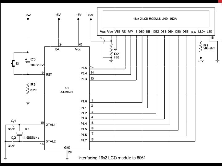
INTERFACING OF LCD WITH 8051
16 X 2 LCD
LCD COMMANDS
ORG 0000 H MOV A, #38 H MOV A, #'S' ACALL CMD ACALL DISP MOV A, #0 EH ACALL CMD MOV A, #01 H ACALL CMD MOV A, #'N' ACALL DISP MOV A, #'J' ACALL DISP MOV A, #06 H ACALL CMD MOV A, #'B‘ ACALL DISP MOV A, #80 H ACALL CMD
L 1: SJMP L 1 DISP: ACALL INIT CMD: ACALL INIT MOV P 1, A SETB P 3. 5 CLR P 3. 4 SETB P 3. 3 ACALL DELAY CLR P 3. 3 RET
INIT: CLR P 3. 3 CLR P 3. 5 MOV P 1, #0 FFH SETB P 3. 4 L 1: SETB P 3. 3 JB P 1. 7, L 1 CLR P 3. 3 DELAY: MOV R 3, #10 L 1: MOV R 4, #250 L 2: DJNZ R 4, L 2 DJNZ R 3, L 1 RET END
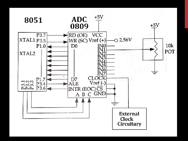
INTERFACING OF ADC 0809 WITH 8051
ADC 0809 • IN 0 -IN 7: Analog Input channels • D 0 -D 7: Data Lines • A, B, C: Analog Channel select lines; • OE: Output enable signal • ALE: Address Latch Enable • EOC: End of Conversion signal • Vref+/Vref-: Differential Reference voltage input • Clock: External ADC clock input
Selected Analog Channel IN 0 IN 1 IN 2 IN 3 IN 4 IN 5 IN 6 IN 7 C B A 0 0 1 1 0 1 0 1
STEPS TO PROGRAM 0809 1. Select an Analog Channel using bits A, B, C 2. Activate ALE (Address Latch Enable) 3. Activate SC(Start of Conversion) 4. Monitor EOC(End of Conversion) 5. Activate OE (Output Enable) to Read Data out.
ALE EQU P 3. 4 OE EQU P 3. 7 START EQU P 3. 5 EOC EQU P 3. 6 SEL_A EQU P 3. 1 SEL_B EQU P 3. 2 SEL_C EQU P 3. 3 ADC_DATA EQU P 1
ORG 0000 H MOV ADC_DATA, #0 FFH ; DATA PORT AS A INPUT SETB EOC ; EOC AS A INPUT CLR ALE ; REST AS A CLR OE OUTPUT CLR START SIGNALS
MAIN: SETB SEL_A CLR SEL_B CLR SEL_C SETB ALE SETB START CLR ALE CLR START ; SELECT ANALOG CHANNEL 1 ; LATCH CHANNEL SELECT ; START CONVERSION
HERE: JB EOC, HERE ; WAIT FOR END OF CONVERSION HERE 1: JNB EOC, HERE 1 SETB OE MOV A, ADC_DATA ; ASSERT READ SIGNAL ; READ DATA ; ADC DATA IS NOW IN ACCUMULATOR CLR OE ; START OVER FOR NEXT CONVERSION SJMP MAIN END
INTERFACING OF 4 X 4 KEYPAD WITH 8051
ORG 0000 H MOV P 1, #1111 B ACALL DELAY ; ITERATION FOR ROW 1 SCANNING MOV P 1, #01111111 B L 0: ; SCAN FOR ROW 1 CJNE P 1, #0111 B, L 1 MOV P 0, #01100000 B ; DISPLAY 1 ACALL L 0 L 1: L 2: L 3: CJNE P 1, #01111011 B, L 2 MOV P 0, #11011010 B ACALL L 0 CJNE P 1, #01111101 B, L 3 MOV P 0, #11110010 B ACALL L 0 CJNE P 1, #01111110 B, L 4 MOV P 0, #1110 B ACALL L 0 ; DISPLAY 2 ; DISPLAY 3 ; DISPLAY A
; ITERATION FOR ROW 2 SCANNING L 4: MOV P 1, #10111111 B ; SCAN FOR ROW 2 CJNE P 1, #10110111 B, L 5 MOV P 0, #0110 B ; DISPLAY 4 ACALL L 0 L 5: CJNE P 1, #1011 B, L 6 MOV P 0, #10110110 B ; DISPLAY 5 ACALL L 0 L 6: CJNE P 1, #10111101 B, L 7 MOV P 0, #10111110 B ; DISPLAY 6 ACALL L 0 L 7: CJNE P 1, #10111110 B, L 8 MOV P 0, #00111110 B ACALL L 0 ; DISPLAY b
; ITERATION FOR ROW 3 SCANNING L 8: MOV P 1, #11011111 B ; SCAN FOR ROW 3 CJNE P 1, #11010111 B, L 9 MOV P 0, #11100000 B ; DISPLAY 7 ACALL L 0 L 9: CJNE P 1, #11011011 B, L 10 MOV P 0, #11111110 B ; DISPLAY 8 ACALL L 0 L 10: CJNE P 1, #1101 B, L 11 MOV P 0, #11110110 B ; DISPLAY 9 ACALL L 0 L 11: CJNE P 1, #11011110 B, L 12 MOV P 0, #10011100 B ACALL L 0 ; DISPLAY C
; ITERATION FOR ROW 4 SCANNING L 12: MOV P 1, #11101111 B ; SCAN FOR ROW 4 CJNE P 1, #11100111 B, L 13 MOV P 0, #10011110 B ; DISPLAY E ACALL L 0 L 13: CJNE P 1, #11101011 B, L 14 MOV P 0, #11111100 B ; DISPLAY 0 ACALL L 0 L 14: CJNE P 1, #11101101 B, L 15 MOV P 0, #10001110 B ; DISPLAY F ACALL L 0 L 15: CJNE P 1, #1110 B, L 0 MOV P 0, #01111010 B ACALL L 0 ; DISPLAY D
DELAY: MOV R 3, #10 L 20: MOV R 4, #250 L 21: DJNZ R 4, L 21 DJNZ R 3, L 20 RET END
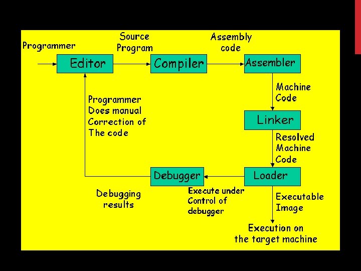
INTEGRATED DEVELOPMENT ENVIRONMENT (IDE) • An Integrated Development Environment (IDE) is software that assists programmers in developing software (and only software!) • IDEs normally consist of a source code editor, a compiler, a linker/locater and usually a debugger. • Sometimes, an IDE is devoted to one specific programming language or one specific processor or hardware, but more often the IDEs support multiple languages, processors, etc • Some commonly used IDEs for embedded systems are the GNU compiler collection (gcc) , Eclipse , Delphi , Kylix , KDevelop , Matlab, Microsoft Visual Studio , Netbeans , Powerbuilder , Dev. C++, Jdeveloper, Intelli. J, etc.
EDITOR • A source code editor is a text editor program designed specifically for editing source code to control embedded systems. • It may be a standalone application or it may be built into an integrated development environment (e. g. IDE) • Source code editors may have features specifically designed to simplify and speed up input of source code, such as syntax highlighting and auto complete functionality. • . These features ease the development of code • Some commonly used editors for embedded systems are BBEdit (for Mac), Emacs (GNU), Kate (KDE), Microsoft Visual Studio (built-in editor) and Vi (vim)
COMPILER • A compiler is a computer program that translates the source code into computer language (object code). • Commonly the output has a form suitable for processing by other programs (e. g. , a linker), but it may be a human-readable text file. • A compiler translates source code from a high level language to a lower level language (e. g. , assembly language or machine language). • The most common reason for wanting to translate source code is to create a program that can be executed on a computer or on an embedded system.
COMPILER • The compiler is called a cross compiler if the source code is compiled to run on a platform other than the on which the cross compiler is run. • For embedded systems the compiler always runs on another platform, so a cross compiler is needed. • A cross compiler is a tool that one must use for a platform where it is inconvenient or impossible to compile on that platform, like micro controllers that run with a minimal amount of memory for their own purpose. • Some commonly used compilers for embedded systems are GCC (GNU), Visual C/C++, CPPBuilder (Delphi/Kylix).
ASSEMBLER • An assembler is a program that translates symbolic code (assembly language) into executable object code. • This object code can be executed with a 80 C 51 -compatible microcontroller. • This sequence of assembler instructions, known as the source code or source program, is specified to the assembler when that program is started • The assembler takes each program statement in the source program and generates a corresponding bit stream or pattern (a series of 0's and 1's of a given length). • The output of the assembler program is called the object code or object program relative to the input source program. • The object program can then be run (or executed) whenever desired.
LINKER • A linker or link editor is a program that takes one or more objects generated by compilers and assembles them into a single executable program or a library that can later be linked to in itself. • All of the object files resulting from compiling must be combined in a special way before the program can be executed. • The object files themselves are individually incomplete, most notably is that some of the internal variable and function references have not yet been resolved. • The job of the linker is to combine these object files and, in the process, to resolve all of the unresolved symbols.
LINKER • Linkers can take objects from a collection called a library. Some linkers do not include the whole library in the output. • They only include its symbols that are referenced from other object files or libraries. Libraries for diverse purposes exist, and one or more system libraries are usually linked in by default. • Unfortunately, the standard library routines often require some changes before they can be used in an embedded program. • The problem here is that the standard libraries provided with most software development tool suites arrive only in object form. So you only rarely have access to the library source code to make the necessary changes yourself.
DEBUGGER • A debugger is a computer program that is used to test and debug other programs. • The code to be examined might alternatively be running on an instruction set simulator (ISS), a technique that allows great power in its ability to halt when specific conditions are encountered but which will typically be much slower than executing the code directly on the appropriate processor. • When the program crashes, the debugger shows the position in the original code if it is a source-level debugger or symbolic debugger. • Often programmers use bugdatabases. A bugdatabase-program makes it possible to database of all the bugs with their description.
SIMULATOR • A simulator is a software that duplicates some processor in almost all the possible ways. • Usually the simulators are used for the testing of new architectures and also to give training in some complex systems. • A simulator is a program which runs on the development system (i. e. your PC) and imitates the architecture of the target processor. • For example an 8051 simulator will contain simulated registers, RAM and other stuff on your PC screen. • example an 8051 simulator will contain simulated registers, RAM and other stuff on your PC screen. You can run your program in this simulator and verify the functionality. You can single step your program, run it up to a certain address, add breakpoints etc.
HARDWARE DEBUGGING TOOLS 1. In-Circuit Emulators 2. Programmers 3. Programmers Development Board 4. Digital Storage Oscilloscope 5. Logic Analyser
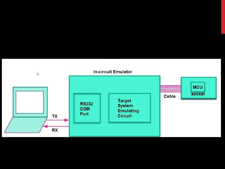
IN CIRCUIT EMULATOR 1. In-circuit emulation (ICE) is used to debug the software of an embedded system. 2. It operates by using a processor with the additional ability to support debugging operations, as well as to carry out the main function of the system. 3. The ICE is temporarily installed between the embedded system and an external terminal or personal computer so that the programmer can observe and alter what takes place in the embedded system, which has no display or keyboard of its own. 4. An ICE serves as a "surrogate" CPU (central processing unit) for the microcomputer in an embedded system. The ICE usually has a connector that fits the CPU socket in the system.
PROGRAMMER
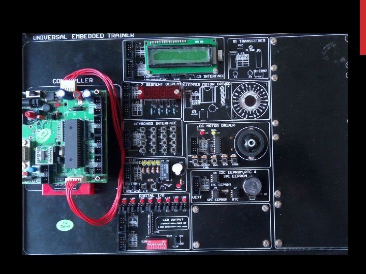
DEVELOPMENT BOARD 1. A microprocessor development board is a printed circuit board containing a microprocessor and the minimal support logic needed for an engineer to become acquainted with the microprocessor on the board and to learn to program it. 2. It also served users of the microprocessor as a method to prototype applications in products. 3. Unlike a general-purpose system such as a home computer, usually a development board contains little or no hardware dedicated to a user interface. 4. It will have some provision to accept and run a usersupplied program, such as downloading a program through a serial port to flash memory, or some form of programmable memory in a socket in earlier systems.
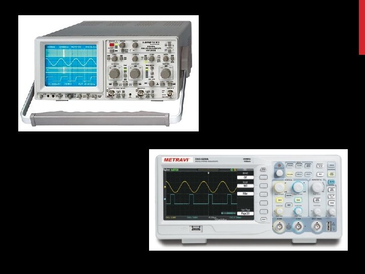
DIGITAL STORAGE OSCILLOSCOPE 1. A digital storage oscilloscope (often abbreviated DSO) is an oscilloscope which stores and analyses the signal digitally rather than using analog techniques. 2. It is now the most common type of oscilloscope in use because of the advanced trigger, storage, display and measurement features which it typically provides. 3. The input analog signal is sampled and then converted into a digital record of the amplitude of the signal at each sample time. 4. The principal advantage over analog storage is that the stored traces are as bright, as sharply defined, and written as quickly as non-stored traces. 5. Traces can be stored indefinitely or written out to some external data storage device and reloaded.
LOGIC ANALYZER 1. logic analyzer is an electronic instrument that captures and displays multiple signals from a digital system or digital circuit. 2. A logic analyzer may convert the captured data into timing diagrams, protocol decodes, state machine traces, assembly language, or may correlate assembly with source-level software. 3. Logic Analyzers have advanced triggering capabilities, and are useful when a user needs to see the timing relationships between many signals in a digital system.