Unit2 Design of Schematic Electronics Circuits Using Multisim


- Slides: 35
Unit-2 Design of Schematic Electronics Circuits Using Multisim
2. 1 Wire, bus, junction, probe, voltage source, current source, and ground etc. used in circuit simulation software
Step-1&2 • Go to place – click component. • Component menu will open up.
Step-3 • Component menu is shown in figure below. • Pickup component from it and place it.
Step-4 • Next use junction function in place tab to create junction as shown in figure below.
Step-5 • Junctions are put in between resisters and for ground as shown in figure.
Step-6 • Next connect junction using wires as shown in figure
Step-7 • Next use wire function in place tab as shown in figure.
Step-8 • Wire command is also use to connect instrument in circuit as shown on figures below.
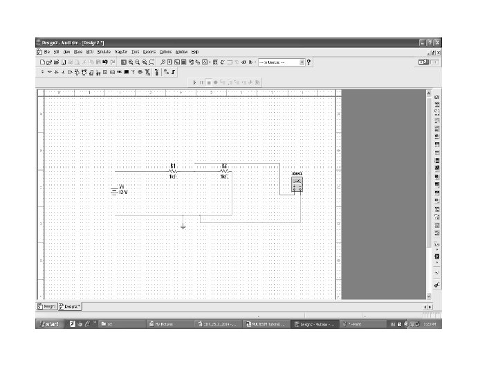
Step-9 • Using component, wire , junction, LED , different sources like AC and pulse etc. make circuit. Example circuits are given in below figure.
2. 2 Create new project, and schematic file.
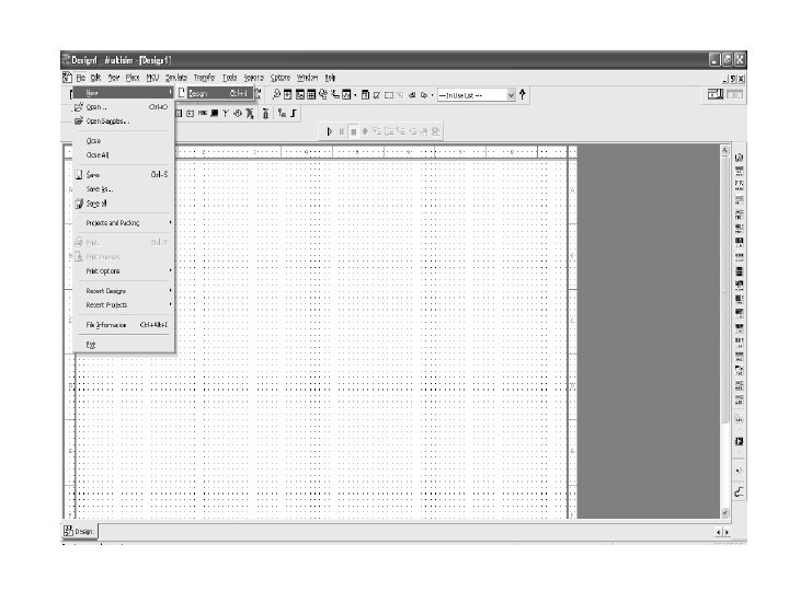
Create new project • First of all for starting of software go to Start • Click on Start --All Programs --National Instruments Circuit Design Suite 11. 0 Multisim
Open/Create Schematic • A blank schematic Circuit 1 is automatically created. • To create a new schematic click on File – New – Schematic Capture. To save the schematic click on File /Save As • To open an existing file click on File/ Open in the toolbar • Click on file—new—design for new file.
Click on save for saving file
For new project click on file—projects and pucking—new project
Next write project name, location and backup location in menu. Click ok
Create project and save it
For save project click on file—project and packing—save project
2. 3 Search , add and create new electronics part
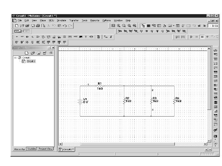
Place Components • To Place Components click on Place/Components. • On the Select Component Window click on Group to select the components needed for the circuit. • Click OK to place the component on the schematic
Resistor
DC Voltage
Figure : 3
Virtual Components • Click on View – Toolbars and select the toolbar needed for the circuit.
Rotate Components • To rotate the components right click on the Resistor to flip the component on 900 Clockwise (Ctrl +R) and 900 Counter Clockwise (Ctrl+Shift+R).
2. 4 Edit , Connect or wire the circuit
Place Wire/Connect Components • To connect resistors click on Place/Wire drag and place the wire. • Components can also be connected by clicking the mouse over the terminal edge of one component and dragging to the edge of another component.
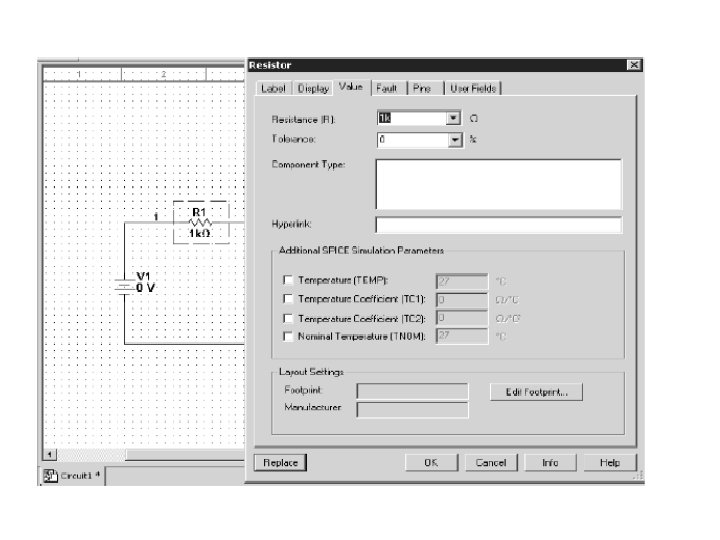
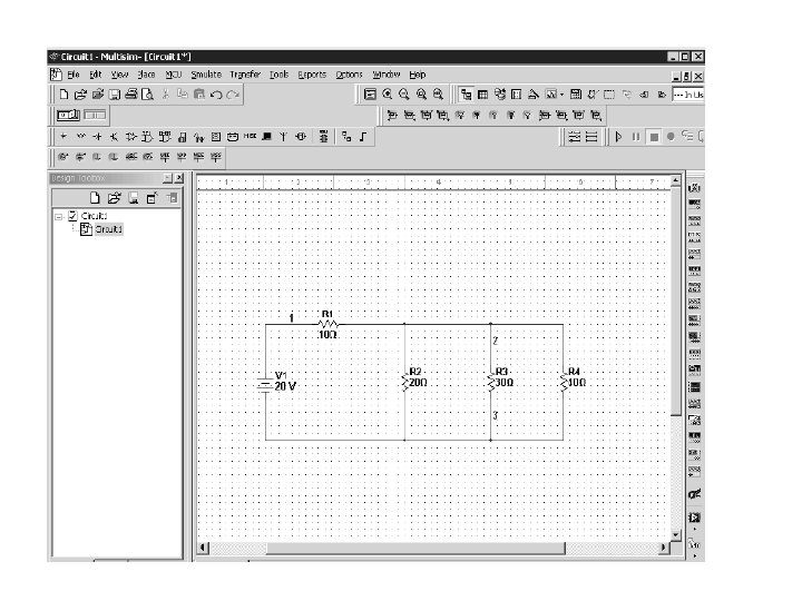
Change Component Values • To change component values double click on the component this brings up a window that display the properties of the component. • For example: • Change R 1 from 1 k Ohm to 10 Ohms, R 2 to 20 Ohms, R 3 to 30 Ohms, and R 4 to 40 Ohms. Also change the DV source from 0 V to 20 V.
Grounding • All circuits must be grounded before the circuit can be simulated. • Click on Ground in the toolbar to ground the circuit. If the circuit is not grounded Multisim will not run the simulation
Simulation • To simulate the completed circuit Click on Simulate/Run or F 5. • This feature can also be accessed from the toolbar as shown in the Figure.