Unit VI Condensation Boiling Heat Transfer in Condensation

Unit VI Condensation & Boiling
 Condensation: Change of phase")
Heat Transfer in Condensation & Boiling (Special Cases of Convection) Condensation: Change of phase from vapor to liquid Boiling: Change of phase from liquid to vapor Important Aspects: • In both cases, Q=mλ; where λ is latent heat • Both phenomena are two phase conversion
: • In both cases, temp")
Heat Transfer in Condensation & Boiling Important Aspects (contd): • In both cases, temp at interface between the liquid and vapor phases is equal to saturation temp (Ts) of the matter • In condensation, the condensate (liquid), while in boiling, the vapor , forms a film over the surface. Properties of this film governs the heat transfer process • At moderate ΔT, very high heat transfer coefficient are obtained (5000 to 50, 000). Hence, where very high Q is needed, two phase convection is used.

Heat Transfer in Condensation & Boiling

Condensation When phase change from vapor to liquid occurs by giving out latent heat to surface, on which it is condensing, which is at a temp lower than saturation temp, the process is called condensation. Types of Condensation 1. Dropwise Condensation 2. Filmwise Condensation

Types of Condensation 1. Dropwise Condensation: • When a saturated vapor comes in contact with a colder surface, it condenses giving out latent heat to surface and liquid droplets are formed on the surface. • These droplets, if they do not have affinity with the surface, instead of getting deposited on the surface, these drop down under gravitational force, leaving the surface bare for successive droplets to form. • Generally, steam has been found to condense in this manner.
: • Experimentally, it has been found that heat transfer rate is")
Dropwise Condensation (Contd): • Experimentally, it has been found that heat transfer rate is much higher than Filmwise condensation ( 5 to 8 times) as the surface remains in direct contact with vapor. • Therefore, dropwise condensation is always desirable. However, it is not achievable for very long time, because once surface gets wet, it results in filmwise condensation. • Some additives/ promoters can maintain and prolong dropwise condensation. Examples are Oliec Acid, highly polished surface etc

Filmwise Condensation: • Due to affinity, droplets form a film of the condensate on the surface and due to gravitational force, it flows down the surface. • Thickness of the film increases in the downwards direction • Due to lower thermal conductivity of the condensate, liquid film offers high resistance to heat flow • Due to the above reasons, heat transfer rate and rate of condensation are lower than dropwise condensation.
 According to")
Film Wise Condensation on Vertical Plate (Nusselt Theory of Laminar Film Condensation) According to Nusselt, the condensed liquid forms a continuous film on the surface and Heat flow rate is determined by thermal resistance of this film. Assumptions: • Flow of condensate in the film is Laminar • Fluid properties are constant • Velocity & thermal BLs are same • Heat transfer across film is due to pure conduction & temp distribution is linear • Liquid-vapor interface is at saturation temp • No shear stress or thermal resistance at liquid-vapor interface

Film Wise Condensation on Vertical Plate • Consider a thin section at a distance of z of thickness dz of vertical plate • From this section, consider a differential CV at a distance of x from the plate of thickness dx in the film • Let the plate be of unit width • Tw is plate temp & Ts interface temp • Let Vz be the velocity of elemental volume in z direction • Let δ be the film thickness at z

Film Wise Condensation on Vertical Plate • Consider CV • Direction of Shear Force Fsx on left face at x will be in upwards dirn while Fsx+dx on right face in downward dirn • Weight of CV W=(dx. dz. 1). ρ. g • Shear Stress ∞ d. Vz/dx

Film Wise Condensation on Vertical Plate • Weight of CV ie, W will act downward • Similarly, Shear Force acting on right face at x+dx will act downward:

Film Wise Condensation on Vertical Plate Hence, writing force balance equation for CV: Fsx=Fsx+dx+W

Film Wise Condensation on Vertical Plate
 At x=0; Vz=0 BC")
Film Wise Condensation on Vertical Plate Boundary Conditions: BC 1) At x=0; Vz=0 BC 2) At x=δ; d. Vz/dx=0 From BC 1) and Eqn (3), we have From BC 2) and eqn (2), we have, 0=0+0+C 2 →C 2=0

Film Wise Condensation on Vertical Plate Now, mass flow rate through CV; dm = ρ(dx. 1). Vz

Film Wise Condensation on Vertical Plate Now, mass flow rate of liquid through section at z can be obtained by integrating dm over film thickness δ:
")
Film Wise Condensation on Vertical Plate Now, rate of condensation(rate of change of mass) at section Z of thickness δ will be dm/dδ Hence, differentiating m wrt δ of eqn …(6);

Film Wise Condensation on Vertical Plate Assuming λ as latent heat; from energy balance at Interface between liquid & Vapor, we can write: Rate of heat released due to condensation of mass dm = Rate of heat conducted through film at z section

Film Wise Condensation on Vertical Plate

Film Wise Condensation on Vertical Plate At elementary section of the wall, steady state heat transfer equation can be written as : Rate of conduction through the film= Rate of heat convection from the film to the wall

Film Wise Condensation on Vertical Plate For obtaining hav for entire length L:

Film Wise Condensation on Vertical Plate

Film Wise Condensation on Vertical Plate This is hav for Film wise Condensation on Vertical Plate

Laminar Flow of Condensate

Condensation Over Inclined Plate

Condensation On Horizontal Tubes Rectangular Array N= No of horizontal Tubes in vertical bank

Condensation: Horizontal v/s Vertical Tubes For max heat transfer, should the tubes in Condenser be kept horizontal or vertical? For hv=hh , we have L/D=2. 86 (=hh/hv ) • When L/D=2. 86, immaterial whether tubes are kept horizontal or vertical • When L/D<2. 86; tubes should be kept vertical • When L/D >2. 86; tubes should be kept horizontal

Q 1: A steam condenser consists of 16 tubes arranged in square array. Water flows through tubes at 65°C while steam at 75°C condenses over the tubes. Find the rate of condensation if: a) Tubes are kept horizontal b) Tubes are kept vertical Take latent heat of steam=2300 k. J/kg and properties of water at 70°C as: ρ=977. 8 kg/m 3, Cp=4. 187 k. J/kg. K, k=0. 668 W/m. K, ν=0. 415 x 10 -6, β=5. 7 x 10 -7. Length of the tubes=120 cm, Dia of the tubes=25 mm Hints: Q=mλ=h. AΔT; m=? For Q=h. AΔT; h=?
 For Horizontal Tubes")
Solution: a) For Horizontal Tubes
 For Vertical Tubes")
Solution: b) For Vertical Tubes

Q 2: A surface condenser was designed for a condensation rate of 50 kg of vapor per hour. It contained 100 tubes of 1 cm OD, 1 m long arranged in square array. The condenser was installed in vertical position (tubes Vertical) by mistake instead of horizontal, for which it was designed. Will there be any change in condensation rate? If yes, find out. Solution: Since total area & ΔT are same in both cases; Q ∞ h and Q=mλ hence Q ∞ m; therefore m ∞ h. Since h values are different for horizontal and vertical layouts, condensation rate will change
:")
Solution (contd):

Q 3: Saturated steam at 80°C condenses on the outside of a horizontal tube of 10 cm dia maintained at temp of 70°C. λ for steam is 2300 k. J/kg. When the tube was kept vertical, it was observed that the rate of condensation was same as before. Find the length of the tube and rate of condensation per hour. Take properties of condensate in the film at 75°C as: ρ=977. 8 kg/m 3 ; k=0. 668 W/m. K; ν=0. 415 x 10 -6 m 2/s

Solution: Since rate of condensation remains same, that means Heat Transfer Rate Q is same, which implies that h in both cases is same ie. hh=hv
:")
Solution (contd):

Q 4: Two configurations are available for a condensing system for steam at 1 atm pressure, consisting of vertical plates maintained at 90 C. The first configuration consists of single vertical plate of height=H and width=W. The second configuration consists of two vertical plates, each of height=H/2 and width=W. Which configuration will you choose for effective condensation? Solution: Case-I: Height =H
: Case-II: Height =H/2 Hence second Configuration will be chosen.")
Solution (contd): Case-II: Height =H/2 Hence second Configuration will be chosen.

Boiling

Boiling When a substance undergoes a phase change from liquid to vapor by taking latent heat from the heating surface, which is at temp higher than the saturation temp of the liquid, the process is called BOILING Types of Boiling 1. Pool Boiling: When heating surface/plate/wire is submerged in the pool of liquid to be boiled, process is called Pool Boiling • Sub cooled Boiling • Saturated Boiling Example: Liquid boiling in a kettle or by wire heater 2. Forced Boiling: Boiling of water in water tubes of a boiler

Six Regimes of Pool Boiling • To study the phenomenon of pool boiling, a log-log plot of heat flux q and excess temp (Tw-Ts) is obtained by measuring heat input and temps on an electrically heated platinum resistance wire submerged in water/liquid. • The Curve thus obtained is known as Pool Boiling Curve. • Curve has three distinct regions, which are further subdivided in to SIX REGIMES
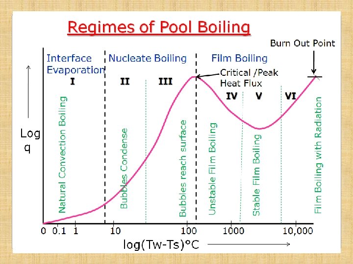

Regimes of Pool Boiling Regime-I • Heat flux increases gradually with increase in temperature difference • Temp diff is of the order of 7 -8°C • Heat transfer takes place just like in natural convection • Heated fluid particles at heating surface rise upwards, thus producing convection current in pool of liquid • Vapor is produced at free surface of the liquid by evaporation, hence this regime is known as Interface Evaporation • Heat flux is proportional to (Tw-Ts)n; where n is slightly higher than 1 (≈1. 3)
: • Heat")
Regimes of Pool Boiling 2. Nucleate Boiling Region (Regime –II & III): • Heat flux increases rapidly with increase in ΔT and reaches Peak value at the end of Regime - III • Temp diff of the order of (Tw-Ts)n; n≈3 (10 to 100°C) Regime-II • With increase in ΔT, bubbles start forming on heating surface at few places. • Bubbles rise upwards but get condensed and do not reach the free surface of the liquid • Intense convection current due to rise of bubbles and hence flux increases rapidly

Regimes of Pool Boiling Regime-III • With further increase in ΔT, large number of bubbles are formed on heating surface at almost all places. • Bubbles grow in size and rise to free surface of liquid, where vapor is released • As the bubbles on forming, leave the heating surface almost immediately, the heating surface becomes available for further bubble formation, hence heat transfer rate continuously increases in this regime and attains max value. • The max value attained at the end of the regime is called Critical Heat Flux (shown in the diagram)

Regimes of Pool Boiling 3. Film Boiling Region : Regime-IV: Unstable Film Regime • With increase in ΔT, the curve starts coming down • Rate of bubble formation becomes very high • These large no of bubbles form a film/blanket over the heating surface • Thermal conductivity of vapor being very small, the film of bubbles acts as shield for heat transfer, hence, Q reduces and curve starts coming down • In this regime , bubble film is unstable, however, it does offer resistance to Q, thus reducing it

Regimes of Pool Boiling Regime-V: Stable Film Region • With further increase in ΔT, the bubbles formation is so high, that the film becomes stable and thus offers more resistance to heat flow • Heat flux thus reduces to minimum • The lowest point on the curve achieved in this regime is known as Leidenfrost Point.

Regimes of Pool Boiling Regime-VI: Radiation Dominant Regime • With further increase in ΔT, the heat flux curve starts rising as the heat transfer by radiation becomes dominant, although stable bubble film remains and does offer same resistance to heat transfer • Temp in this regime is very high, of the order of 104 °C • With slight increase in heat flux above Critical Heat Flux, the temp of heating surface becomes so high that no heating body/surface/wire will be able to withstand that temp and will melt away. • This point on the curve is called Burn Out Point

Importance of Critical Heat Flux & Burn Out Points • From the curve, it can be seen that heat transfer rate decreases beyond Peak Flux, even on increasing the heating temperature. • Now, by obtaining even slight increase in heat flux above peak value, it will give rise to very high temp. • At this high temp, most of the metals will melt/fail/ burn out called Burn Out Point • So, there is no point in going above the Peak Flux heat transfer rate, while designing equipment for max possible heat transfer rate.

Correlations in Pool Boiling 1. Natural Convection Boiling: All properties of fluid to be taken at (Tw+Ts)/2
: All properties of fluid to")
Correlations in Pool Boiling 2. Nucleate Boiling (Rohsenhow’s Relation): All properties of fluid to be taken at Tsat
: All properties of fluid")
Correlations in Pool Boiling 3. Critical Heat Flux (Zuber Relation): All properties of fluid to be taken at Tsat
 Boiling • When a liquid is forced to flow through a tube,")
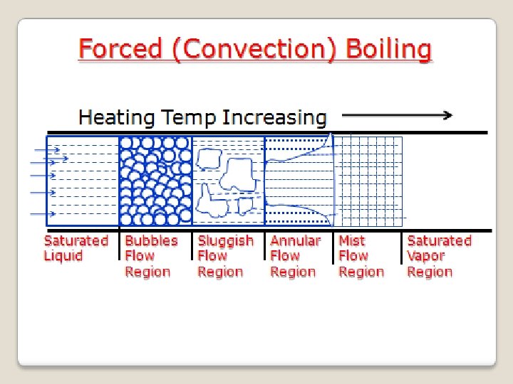
Forced (Convection) Boiling • When a liquid is forced to flow through a tube, which is being heated continuously from outside surface, the process of boiling is known as Forced Boiling. Example : Production of steam in a boiler tube • When saturated liquid is forced to flow, the following regions are observed along the length of pipe, when saturated fluid is getting converted to vapor: 1. Bubble Flow Region: Vapor bubbles form here and these can be observed with saturated fluid in this region 2. Sluggish Flow Region: Large number of vapor bubbles coagulate to form large vapors and they flow along with saturated liquid
 3. Annular Flow Region: Here large vapor masses formed in the")
Forced Boiling (Continued) 3. Annular Flow Region: Here large vapor masses formed in the earlier region combine and flow through the central region of the tube, while the liquid flows in annular passage around the vapor core 4. Mist Flow Region: In the previous region, thickness of annular ring of liquid goes on decreasing and then vanishes at the end the region. Now there are vapor with suspended liquid particles and is known as Mist Flow. Finally, suspended liquid particles also get evaporated at the end of this region to give saturated vapor, which become invisible to our eyes

End of Condensation & Boiling
°C")
Regimes of Pool Boiling Burn Out Point 0 0. 1 1 10 100 log(Tw-Ts)°C Unstable Film Boiling 1000 10, 000 Film Boiling with Radiation Critical /Peak Heat Flux IV V VI III Bubbles reach surface II Bubbles Condense Log q Natural Convection Boiling I Film Boiling Stable Film Boiling Interface Nucleate Boiling Evaporation
 Boiling Heating Temp Increasing Saturated Liquid Bubbles Flow Region Sluggish Flow Region")
Forced (Convection) Boiling Heating Temp Increasing Saturated Liquid Bubbles Flow Region Sluggish Flow Region Annular Flow Region Mist Flow Region Saturated Vapor Region
- Slides: 58