UNIT V RTOS SERVICESOther RTOS Services Other RTOS


 component allows for distributed computing. The")


, also known as the timer chip")


 have")


- Slides: 67
UNIT V RTOS SERVICESOther RTOS Services
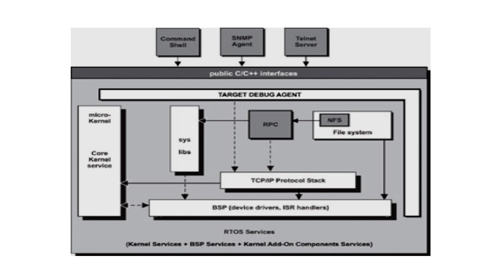
Other RTOS Services • A good real-time embedded operating system avoids implementing the kernel as a large, monolithic program. The kernel is developed instead as a micro-kernel. The goal of the micro-kernel design approach is to reduce essential • kernel services into a small set and to provide a framework in which other optional kernel services can be implemented as independent modules. These modules can be placed outside the kernel. Some of these modules arepart of special server tasks.
This structured approach makes it possible to extend the kernel by adding additional services or to modify existing services without affecting users. This level of implementation flexibility is highly desirable. The resulting benefit is increased system configurability because each embedded application requires a specific set of system services with respect to its characteristics. This combination can be quite different from application to application. The micro-kernel provides core services, including task-related services, the scheduler service, and synchronization primitives.
File system component.
Remote procedure calls. The remote procedure call (RPC) component allows for distributed computing. The RPC server offers services to external systems as remotely callable procedures. A remote RPC client can invoke these procedures over the network using the RPC protocol. To use a service provided by an RPC server, a client application calls routines, known as stubs, provided by the RPC client residing on the local machine.
The user can invoke commands, such as ping , ls , loader , androute through the shell. The shell interprets these commands and makes corresponding calls into RTOS routines.
Points to Remember Some points to remember include the following: · Micro-kernel design promotes a framework in which additional service components can be developed to extend the kernel's functionalities easily. · Debug agents allow programmers to debug every piece of code running on target systems. · Exceptions and Developers should choose a host debugger that understands many different RTOS debug agents. Interrupts · Components can be included and configured through a set of system configuration files. · Developers should only include the necessary components to safeguard memory efficiency
Exceptions and Interrupts Exceptions and interrupts are part of a mechanism provided by the majority of embedded processor architectures to allow for the disruption of the processor's normal execution path. This disruption can be triggered either intentionally by application software or by an error, unusual condition, or some unplanned external event. the definitions of exception and interrupt, · the applications of exceptions and interrupts, · a closer look at exceptions and interrupts in terms of hardware support, classifications, priorities, and causes of spurious interrupts, and · a detailed discussion on how to handle exceptions and interrupts.
What are Exceptions and Interrupts? An exception is any event that disrupts the normal execution of the processor and forces the processor into execution of special instructions in a privileged state. Exceptions can be classified into two categories: synchronous exceptions and asynchronous exceptions. Exceptions raised by internal events, such as events generated by the execution of processor instructions, are called synchronous exceptions. Examples of synchronous exceptions include the following: · On some processor architectures, the read and the write operations must start at an even memory address for certain data sizes. Read or write operations that begin at an odd memory address cause a memory access error event and raise an exception (called an alignment exception ). · An arithmetic operation that results in a division by zero raises an exception.
Exceptions raised by external events, which are events that do not relate to the execution of processor instructions, are called asynchronous exception s. In general, these external events are associated with hardware signals. The sources of these hardware signals are typically external hardware devices. Examples of asynchronous exceptions include the following: · Pushing the reset button on the embedded board triggers an asynchronous exception (called the system reset exception ). · The communications processor module that has become an integral part of many embedded designs is another example of an external device that can raise asynchronous exceptions when it receives data packets. An interrupt, sometimes called an external interrupt, is an asynchronous exception triggered by an event that an external hardware device generates.
Because the term interrupt has been used extensively in other texts, therefore, the text that follows uses exceptions to mean synchronous exceptions and interrupts to mean asynchronous exceptions. The book uses general exceptions to mean both. The term interrupts and external interrupts are used interchangeably throughout the text. Applications of Exceptions and Interrupts internal errors and special conditions management, · hardware concurrency, and · service requests management.
Internal Errors and Special Conditions Management Handling and appropriately recovering from a wide range of errors without coming to a halt is often necessary in the application areas in which embedded systems are typically employed. Exceptions are either error conditions or special conditions that the processor detects while executing instructions. Error conditions can occur for a variety of reasons. If some unanticipated condition occurs that causes a division by zero, over-flow, or other math error, the application must be warned. In this case, the execution of the task performing the calculation halts, and a special exception service routine begins. This process gives the application an opportunity to evaluate and appropriately handle the error. Other types of errors include memory read or write failures (a common symptom of a stray pointer), or attempts to access floating-point hardware when not installed.
Many processor architectures have two modes of execution: normal and privileged. Some instructions, called privileged instructions, are allowed to execute only when the processor is in the privileged execution mode. An exception is raised when a privileged instruction is issued while the processor is in normal execution mode Special conditions are exceptions that are generated by special instructions, such as the TRAP instruction on the Motorola 68 K processor family. These instructions allow a program to force the processor to move into privileged execution mode, consequently gaining access to a privileged instruction set. For example, the instruction used to disable external interrupts must be issued in privileged mode. Another example of a special condition is the trace exception generated by the break point feature available on many processor architectures. The debugger agent, a special software program running on the embedded device, handles this exception, which makes using a host debugger to perform software break point and code stepping possible.
Hardware Concurrency and Service Request Management The ability to perform different types of work simultaneously is important in embedded systems. Many external hardware devices can perform device-specific operations in parallel to the core processor. These devices require minimum intervention from the core processor. The key to concurrency is knowing when the device has completed the work previously issued so that additional jobs can be given. External interrupts are used to achieve this goal. A Closer Look at Exceptions and Interrupts General exceptions have classifications and are prioritized based on the classifications
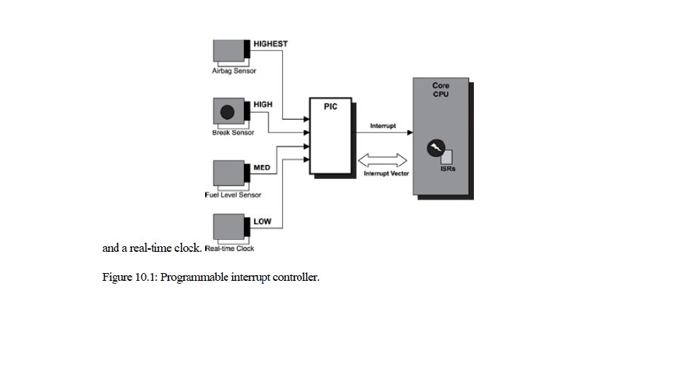
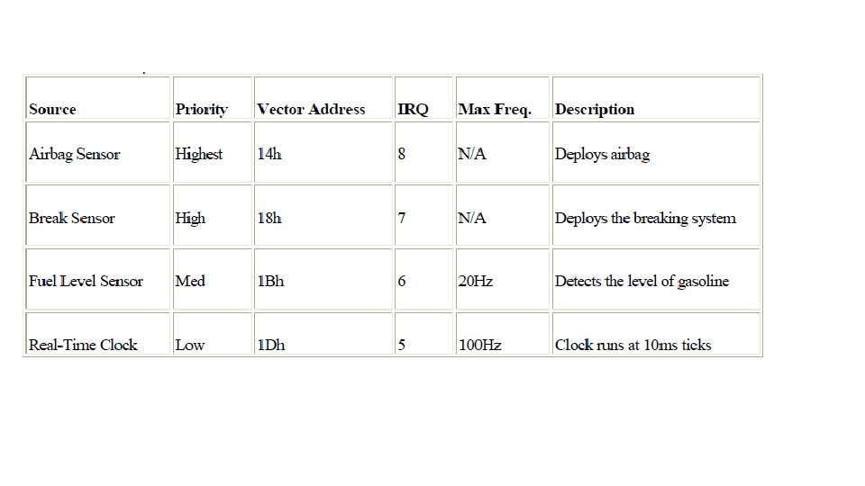
Programmable Interrupt Controllers and External Interrupts Most embedded designs have more than one source of external interrupts, and these multiple external interrupt sources are prioritized. To understand how this process is handled, a clear understanding of the concept of a programmable interrupt controller (PIC) is required. The PIC is implementation-dependent. It can appear in a variety of forms and is sometimes given different names, however, all serve the same purpose and provide two main functionalities: · Prioritizing multiple interrupt sources so that at any time the highest priority interrupt is presented to the core CPU for processing. · Offloading the core CPU with the processing required to determine an interrupt's exact source.
Classification of General Exceptions Although not all embedded processors implement exceptions in the same manner, most of the more recent processors have these types of exceptions: asynchronous-non-maskable, asynchronous-maskable, synchronous-precise, synchronous-imprecise.
Processing General Exceptions The overall exception handling mechanism is similar to the mechanism for interrupt handling. In a simplified view, the processor takes the following steps when an exception or an external interrupt is raised: Save the current processor state information. Load the exception or interrupt handling function into the program counter. Transfer control to the handler function and begin execution. Restore the processor state information after the handler function completes. Return from the exception or interrupt and resume previous execution. A typical handler function does the following: Switch to an exception frame or an interrupt stack. Save additional processor state information. Mask the current interrupt level but allow higher priority interrupts to occur. Perform a minimum amount of work so that a dedicated task can complete the main processing
Points to Remember · Exceptions are classified into synchronous and asynchronous exceptions. · Exceptions are prioritized. · External interrupts belong to the category of asynchronous exceptions. · External interrupts are the only exceptions that can be disabled by software. · Exceptions can be nested. · Using a dedicated exception frame is one solution to solving the stack overflow problem that nested exceptions cause. · Exception processing should consider the overall timing requirements of the system devices and tasks. · Spurious interrupts can occur and should be handled as any other interrupts.
Timer and Timer Services In embedded systems, system tasks and user tasks often schedule and perform activities after some time has elapsed. For example, a RTOS scheduler must perform a context switch of a preset time interval periodically-among tasks of equal priorities-to ensure execution fairness when conducting a round-robin scheduling algorithm. A software-based memory refresh mechanism must refresh the dynamic memory every so often or data loss will occur. In embedded networking devices, various communication protocols schedule activities for data retransmission and protocol recovery. The target monitor software sends system information to the host-based analysis tool periodically to provide system-timing diagrams for visualization and debugging.
Most embedded systems use two different forms of timers to drive time-sensitive activities: hard timers and soft timers. Hard timers are derived from physical timer chips that directly interrupt the processor when they expire. Operations with demanding requirements for precision or latency need the predictable performance of a hard timer. Soft timers are software events that are scheduled through a software facility.
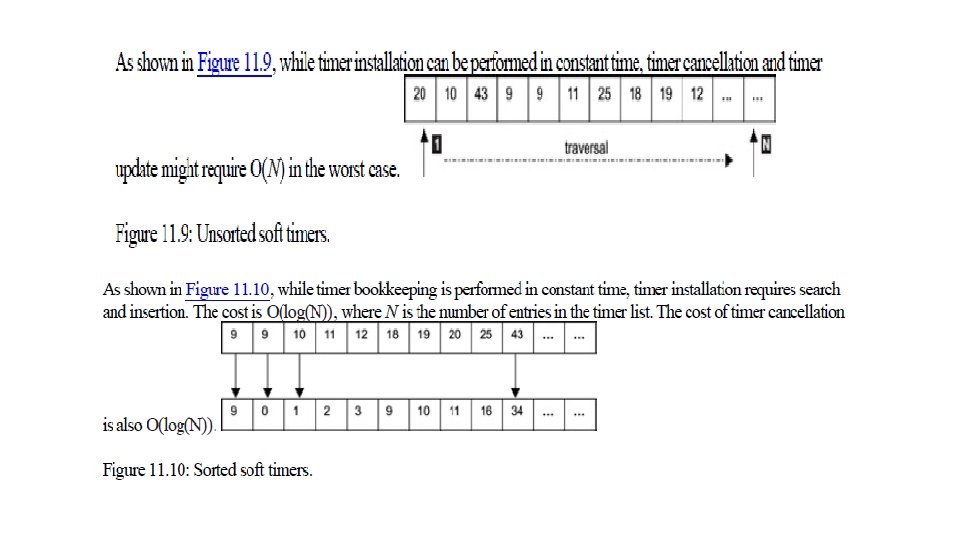
A soft-timer facility allows for efficiently scheduling of non-highprecision software events. A practical design for the soft-timer handling facility should have the following properties: · efficient timer maintenance, i. e. , counting down a timer, · efficient timer installation, i. e. , starting a timer, and · efficient timer removal, i. e. , stopping a timer
This chapter focuses on: · real-time clocks versus system clocks, · programmable interval timers, · timer interrupt service routines, · timer-related operations, · soft timers, and · implementing soft-timer handling facilities
Real-Time Clocks and System Clocks In some references, the term real-time clock is interchangeable with the term system clock.
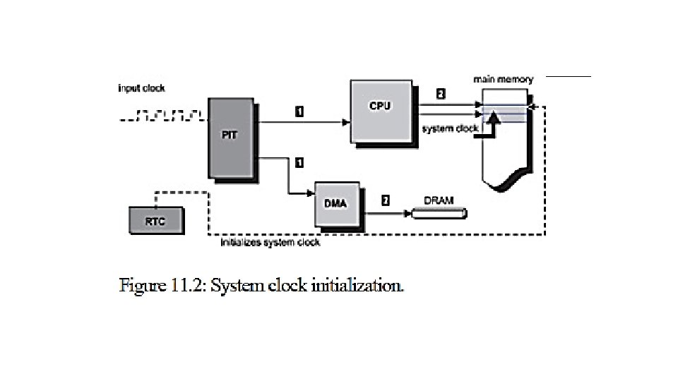
Programmable Interval Timers The programmable interval timer (PIT), also known as the timer chip , is a device designed mainly to function as an event counter, elapsed time indicator, rate-controllable periodic event generator, as well as other applications for solving system-timing control problems. The functionality of the PIT is commonly incorporated into the embedded processor, where it is called an on-chip timer.
Timer-chip initialization is performed as part of the system startup. Generally, initialization of the timer chip involves the following steps: · Resetting and bringing the timer chip into a known hardware state. · Calculating the proper value to obtain the desired timer interrupt frequency and programming this value into the appropriate timer control register. · Programming other timer control registers that are related to the earlier interrupt frequency with correct values. This step is dependent on the timer chip and is specified in detail by the timer chip hardware reference manual. · Programming the timer chip with the proper mode of operation. · Installing the timer interrupt service routine into the system. · Enabling the timer interrupt. The behavior of the timer chip output is programmable through the control registers, the most important of which is the timer interrupt-rate register (TINTR).
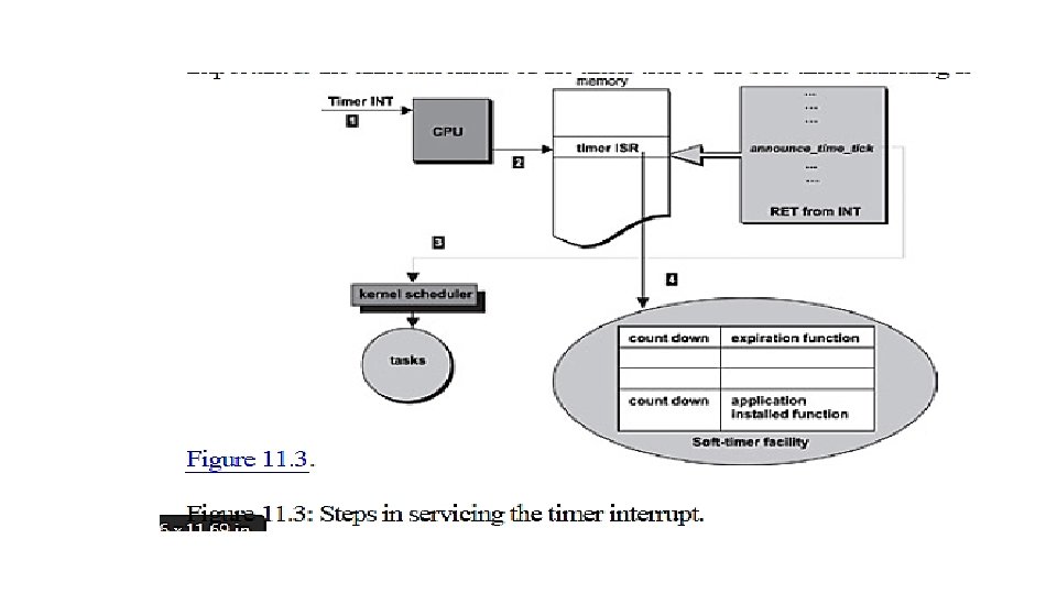
Timer Interrupt Service Routines Part of the timer chip initialization involves installing an interrupt service routine (ISR) that is called when the timer interrupt occurs. Typically, the ISR performs these duties: · Updating the system clock-Both the absolute time and elapsed time is updated. Absolute time is time kept in calendar date, hours, minutes, and seconds. Elapsed time is usually kept in ticks and indicates how long the system has been running since power up. · Calling a registered kernel function to notify the passage of a preprogrammed period-For the following discussion, the registered kernel function is called announce_time_tick. · Acknowledging the interrupt, reinitializing the necessary timer control register(s), and returning from interrupt.
Possible Processing Delays
Implementation Considerations
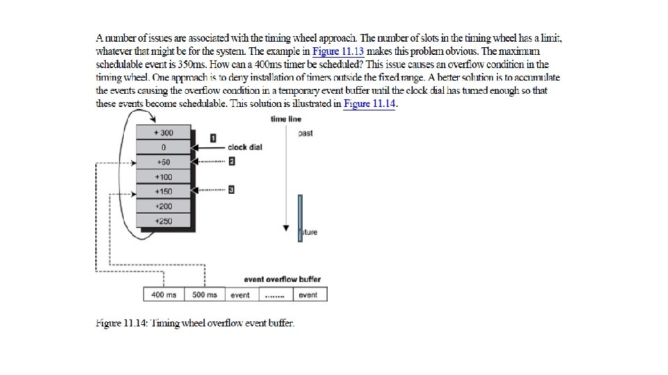
A soft-timer facility built using the timing-wheel approach provides efficient operations for installation, cancellation, and timer bookkeeping.
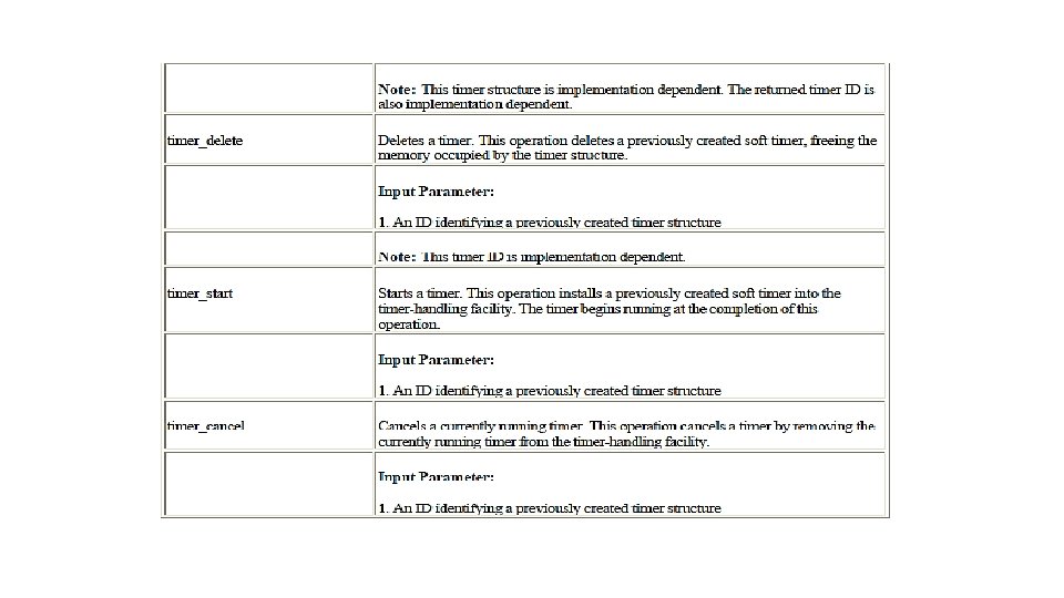
Soft Timers and Timer Related Operations Many RTOSs provide a set of timer-related operations for external software components and applications through API sets. These common operations can be cataloged into these groups: · group 1 -provides low-level hardware related operations, · group 2 -provides soft-timer-related services, and · group 3 -provides access either to the storage of the real-time clock or to the system clock. Not all of the operations in each of these three groups, however, are offered by all RTOSs, and some RT
The first group of operations is developed and provided by the BSP developers. The group is considered low-level system operations. Each operation in the group is given a fictitious function name for this discussion. Actual function names are implementation dependent.
The second group of timer-related operations includes the core timer operations that are heavily used by both the system modules and applications. Either an independent timer-handling facility or a built-in one that is part of the kernel offers these operations. Each operation in the group is given a fictitious function name for this discussion. Actual function names are implementation dependent.
The third group is mainly used by user-level applications. The operations in this group interact either with the system clock or with the real-time clock. A system utility library offers these operations. Each operation in the group is given a fictitious function name for this discussion. Actual function names are implementation dependent.
I/O Subsystem From the perspective of a system software developer, I/O operations imply communicating with the device, programming the device to initiate an I/O request, performing actual data transfer between the device and the system, and notifying the requestor when the operation completes. The system software engineer must understand the physical properties, such as the register definitions, and access methods of the device. Locating the correct instance of the device is part of the device communications when multiple instances of the same device are present. The system engineer is also concerned with how the device is integrated with rest of the system. The system engineer is likely a device driver developer because the system engineer must know to handle any errors that can occur during the I/O operations. From the perspective of the RTOS, I/O operations imply locating the right device for the I/O request, locating the right device driver for the device, and issuing the request to the device driver. Sometimes the RTOS is required to ensure synchronized access to the device. The RTOS must facilitate an abstraction that hides both the device characteristics and specifics from the application developers.
From the perspective of an application developer, the goal is to find a simple, uniform, and elegant way to communicate with all types of devices present in the system. The application developer is most concerned with presenting the data to the end user in a useful way. Each perspective is equally important and is examined in this chapter. This chapter focuses on: · basic hardware I/O concepts, · the structure of the I/O subsystem, and · a specific implementation of an I/O subsystem.
Basic I/O Concepts The combination of I/O devices, associated device drivers, and the I/O subsystem comprises the overall I/O system in an embedded environment. The purpose of the I/O subsystem is to hide the device-specific information from the kernel as well as from the application developer and to provide a uniform access method to the peripheral I/O devices of the system. This section discusses some fundamental concepts from the perspective of the device driver developer. Figure 12. 1 illustrates the I/O subsystem in relation to the rest of the system in a layered software model. As shown, each descending layer adds additional detailed information to the architecture needed to manage a given device.
Port-Mapped vs. Memory-Mapped I/O and DMA When the I/O device address space is separate from the system memory address space, special processor instructions, such as the IN and OUT instructions offered by the Intel processor, are used to transfer data between the I/O device and a microprocessor register or memory. The I/O device address is referred to as the port number when specified for these special instructions. This form of I/O is called port-mapped I/O, as shown in Figure 12. 2.
The devices are programmed to occupy a range in the I/O address space. Each device is on a different I/O port. The I/O ports are accessed through special processor instructions, and actual physical access is accomplished through special hardware circuitry. This I/O method is also called isolated I/O because the memory space is isolated from the I/O space, thus the entire memory address space is available for application use.
The other form of device access is memory-mapped I/O, as shown in Figure 12. 3. In memory-mapped I/O, the device address is part of the system memory address space. Any machine instruction that is encoded to transfer data between a memory location and the processor or between two memory locations can potentially be used to access the I/O device. The I/O device is treated as if it were another memory location. Because the I/O address space occupies a range in the system memory address space, this region of the memory address space is not available for an application to use.
The processor has to do some work in both of these I/O methods. Data transfer between the device and the system involves transferring data between the device and the processor register and then from the processor register to memory. The transfer speed might not meet the needs of high-speed I/O devices because of the additional data copy involved. Direct memory access (DMA) chips or controllers solve this problem by allowing the device to access the memory directly without involving the processor, as shown in Figure 12. 4. The processor is used to set up the DMA controller before a data transfer operation begins, but the processor is bypassed during data transfer, regardless of whether it is a read or write operation. The transfer speed depends on the transfer speed of the I/O device, the speed of the memory device, and the speed of the DMA controller.
Character-Mode vs. Block-Mode Devices I/O devices are classified as either character-mode devices or block-mode devices. The classification refers to how the device handles data transfer with the system. Character-mode devices allow for unstructured data transfers. The data transfers typically take place in serial fashion, one byte at a time. Character-mode devices are usually simple devices, such as the serial interface or the keypad. The driver buffers the data in cases where the transfer rate from system to the device is faster than what the device can handle. Block-mode devices transfer data one block at time, for example, 1, 024 bytes per data transfer. The underlying hardware imposes the block size. Some structure must be imposed on the data or some transfer protocol enforced. Otherwise an error is likely to occur. Therefore, sometimes it is necessary for the block-mode device driver to perform additional work for each read or write operation, as shown in Figure 12. 5.
Servicing a write operation for a block-mode device.
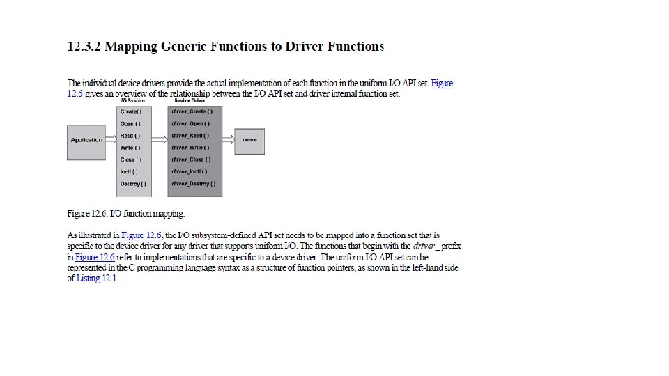
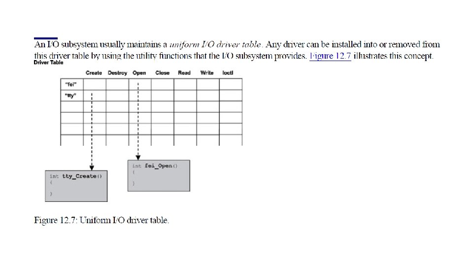
The I/O Subsystem Each I/O device driver can provide a driver-specific set of I/O application programming interfaces to the applications. This arrangement requires each application to be aware of the nature of the underlying I/O device, including the restrictions imposed by the device. The API set is driver and implementation specific, which makes the applications using this API set difficult to port. To reduce this implementation-dependence, embedded systems often include an I/O subsystem. The I/O subsystem defines a standard set of functions for I/O operations in order to hide device peculiarities from applications. All I/O device drivers conform to and support this function set because the goal is to provide uniform I/O to applications across a wide spectrum of I/O devices of varying types.
The following steps must take place to accomplish uniform I/O operations at the application-level. 1. The I/O subsystem defines the API set. 2. The device driver implements each function in the set. 3. The device driver exports the set of functions to the I/O subsystem. 4. The device driver does the work necessary to prepare the device for use. In addition, the driver sets up an association between the I/O subsystem API set and the corresponding device-specific I/O calls. 5. The device driver loads the device and makes this driver and device association known to the I/O subsystem. This action enables the I/O subsystem to present the illusion of an abstract or virtual instance of the device to applications.
The I/O subsystem presented in the example in this section defines a set of functions as the standard I/O function set.
Note that all these functions operate on a so-called 'virtual instance' of the I/O device. In other words, these functions do not act directly on the I/O device, but rather on the driver, which passes the operations to the I/O device. When the open, read, write, and close operations are described, these operations should be understood as acting indirectly on an I/O device through the agency of a virtual instance.
Memory Management Many embedded devices (such as PDAs, cell phones, and digital cameras) have a limited number of applications (tasks) that can run in parallel at any given time, but these devices have small amounts of physical memory onboard. Larger embedded devices (such as network routers and web servers) have more physical memory installed, but these embedded systems also tend to operate in a more dynamic environment, therefore making more demands on memory. Regardless of the type of embedded system, the common requirements placed on a memory management system are minimal fragmentation, minimal management overhead, and deterministic allocation time.
This chapter focuses on: · memory fragmentation and memory compaction, · an example implementation of the malloc and free functions, · fixed-size, pool-based memory management, · blocking vs. non-blocking memory functions, and · the hardware memory management unit (MMU).
Dynamic Memory Allocation in Embedded Systems In general, a memory management facility maintains internal information for a heap in a reserved memory area called the control block. Typical internal information includes: the starting address of the physical memory block used for dynamic memory allocation, the overall size of this physical memory block, and the allocation table that indicates which memory areas are in use, which memory areas are free, and the size of each free region. This chapter examines aspects of memory management through an example implementation of the malloc and free functions for an embedded system.
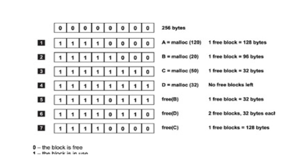
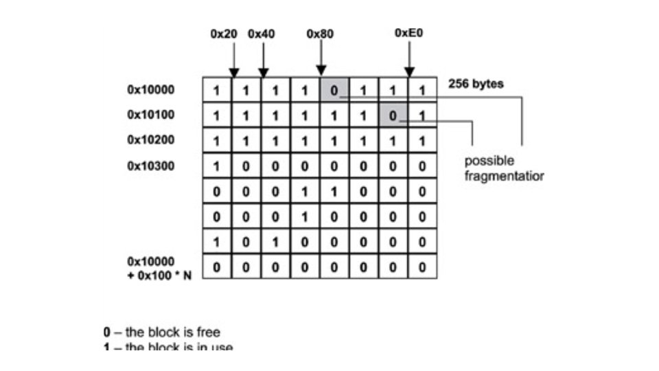
Memory Fragmentation and Compaction In the example implementation, the heap is broken into small, fixed-size blocks. Each block has a unit size that is power of two to ease translating a requested size into the corresponding required number of units. In this example, the unit size is 32 bytes. The dynamic memory allocation function, malloc, has an inpu parameter that specifies the size of the allocation request in bytes. mallocates a larger block, which is made up of one or more of the smaller, fixed-size blocks. The size of this larger memory block is at least as large as the requested size; it is the closest to the multiple of the unit size. For example, if the allocation requests 100 bytes, the returned block has a size of 128 bytes (4 units x 32 bytes/unit). As a result, the requestor does not use 28 bytes of the allocated memory, which is called memory fragmentation. This specific form of fragmentation is called internal fragmentation because it is internal to the allocated block.
shows another example of the state of an allocation table. Note that two free 32 -byte blocks are shown. One block is at address 0 x 10080, and the other at address 0 x 101 C 0, which cannot be used for any memory allocation requests larger than 32 bytes. Because these isolated blocks do not contribute to the contiguous free space needed for a large allocation request, their existence makes it more likely that a large request will fail or take too long. The existence of these two trapped blocks is considered external fragmentation because the fragmentation exists in the table, not within the blocks themselves. One way to eliminate this type of fragmentation is to compact the area adjacent to these two blocks. The range of memory content from address 0 x 100 A 0 (immediately following the first free block) to address 0 x 101 BF (immediately preceding the second free block is shifted 32 bytes lower in memory, to the new range of 0 x 10080 to 0 x 1019 F, which effectively combines the two free blocks into one 64 byte block. This new free block is still considered memory fragmentation if future allocations are potentially larger than 64 bytes. Therefore, memory compaction continues until all of the free blocks are combined into one large chunk.