UNIT V NETWORK DESIGN Network layout develops various

logical diagrams, (ii)physical")


- Slides: 19
UNIT – V NETWORK DESIGN
Network layout develops various views of planned network design including detailed (i)logical diagrams, (ii)physical blue prints and (iii) function - specific component plans
LOGICAL DIAGRAMS 1. They show the connectivity and relationships among network devices. 2. Relationships show devices may interact with one another , how they work together and what you might expect from them 3. These diagrams do not accurately represent the location of different devices, they give only an approximate representations 4. These diagrams are useful for planning purposes
LOGICAL DIAGRAMS
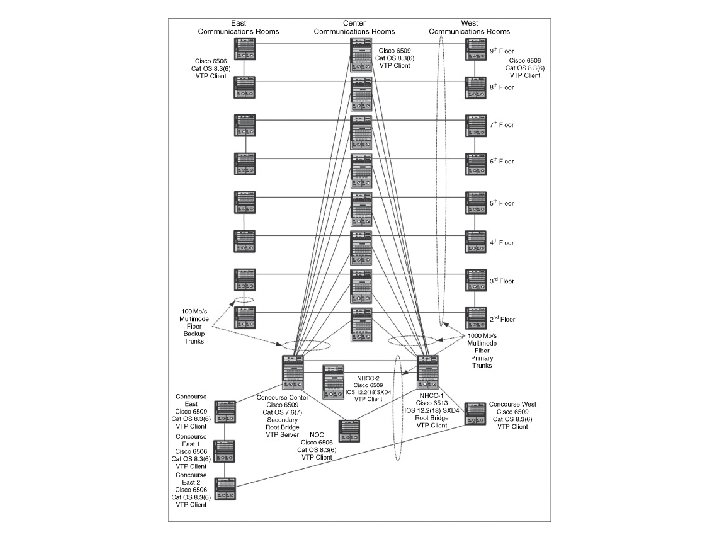
NETWORK BLUE PRINTS 1. These diagrams describe detailed physical aspects of networking design, which specify network devices, cables , servers , plants and physical security. And secure locations, how they are to be interconnected. 2. These blue prints can consist of single diagram or sets of diagrams, depending on network size. 3. These consist of mapping strategic locations of network onto network templates
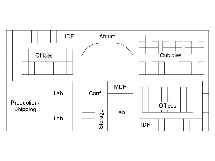
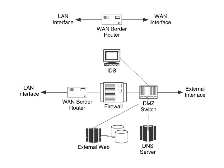
MAPPING STRATEGIC LOCATIONS 1. As part of the network blue prints, physical information , like the building plan, location of different rooms. . Etc would have been collected. 2. Using these we map strategic locations for the network 3. Some examples of possible strategic locations on network functions are 1. Boundary points between secuirty cell ones 2. Location of major components for moitoring and management 3. Aggregation of routes, networks and or traffic flows
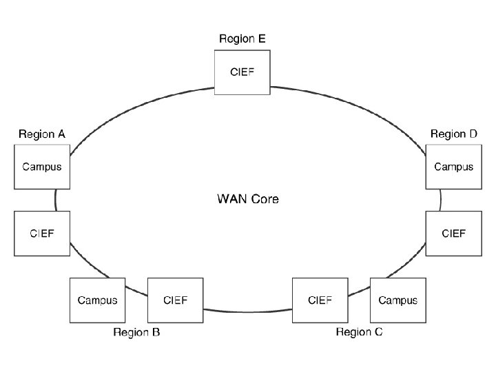
Applying topology Selections 1. The choice of strategic locations should map to selected topologys 2. Topology choices describe the high level structure of network and consists of major locations that support this structure
This adds diversity to the network.
Addition of technology choices to the network according to architectural process
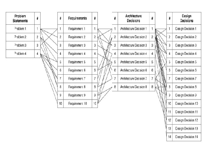
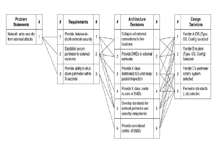
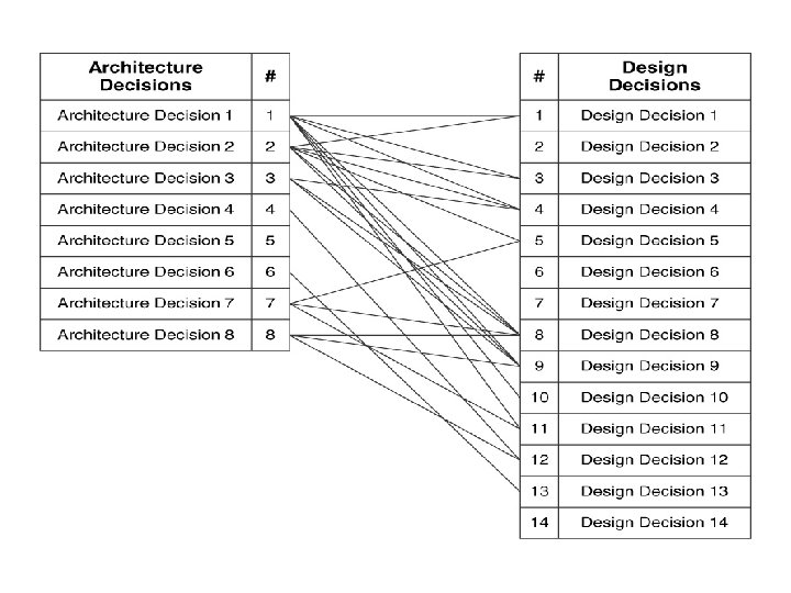
DESIGN TRACEBILITY 1. Each design decision regarding network should be tracebale to one or more architectural decisions and thus to requirements and problem statements 2. Each design decision maps to one or more architectural decisions which inturn maps to requirements , inturn maps to problem statements 3. Traceability indicates how well your network design addresses, reqiorements and problem statements
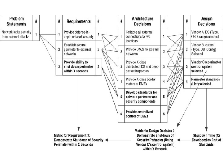
DESIGN METRICS 1. Each validated requirement should be mapped to one or more metrics, and these metrics are used to determine the success of in meeting each requirement 2. The metrics associated with design should be coupled to metrics used in requirements 3. Examples of design metrics include, the ability to achieve a desired diversity level in the network, via routing , topology, equipment redundancy…etc, often associated with metrics for performance requirements such as n/w availability and reliability 4. Similarly the ability to bound round trip time and or end to end delay is again associated with performance of service delivery requirements