UNIT V GOVERNORS GYROSCOPES Syllabus Governors Types Centrifugal

UNIT –V GOVERNORS & GYROSCOPES

Syllabus Governors � Types - Centrifugal governors - Gravity controlled and spring controlled centrifugal governors – � Characteristics - Effect of friction Controlling force curves. Gyroscopes � Gyroscopes –Gyroscopic forces and torques – Gyroscopic stabilization – Gyroscopic effects in Automobiles, ships and airplanes.

Governor: � Governor is an automatic speed control mechanism. � The function of a governor is to maintain the speed of an engine within specified limits whenever there is a variation of load. � Governor keeps the speed of the engine within certain limits by regulating the fuel supply as per load requirements.

Function of governor � If the load on the engine increases, its speed decreases. So it becomes necessary to increase the fuel supply by opening the throttle valve. � On the other hand, when the load on the engine decreases, its speed increases and the fuel supply is to be decreases by closing the throttle valve , which is operated by a governor through a mechanism. � In petrol engines, governor manipulates the throttle valve and in diesel engines, it manipulates the fuel pump.

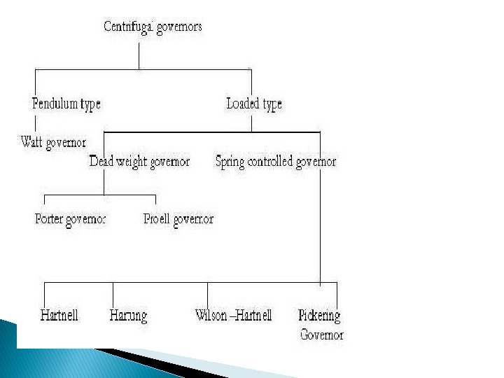
Classification of governors: � Governors are classified based upon two different categories. These are: 1. Centrifugal governors 2. Inertia governors Centrifugal governors: � The centrifugal governors are working based on the balancing of centrifugal force on the rotating balls by an equal and opposite radial force, known as the controlling force. � It consists of two balls of equal mass, which are attached to the arms. These balls are known as governor balls or fly balls.

Centrifugal governor

Centrifugal governor arrangement � In centrifugal governor, rotation of the crank shaft is taken to a vertical spindle through suitable gears. � Consists of two balls of equal mass, which are attached to the arms. � The upper arms are keyed to the spindle and the lower arms which are known as links are connected to sleeve. � The sleeve surrounds the spindle and can rotate as well as slide over the spindle. � One end of the bell-crank lever is attached to the sleeve and the other to a rod which actuates the fuel supply valve

Working of centrifugal governor � Working based on the balancing of centrifugal force on the rotating balls by an equal and opposite radial force. � When the load on the engine decreases, the engine and the governor speed increases. This increases the centrifugal force acting on the balls and the balls move radially outwards. � Therefore the sleeve rises upwards, this upward movement of the sleeve reduces the supply of fuel and hence the speed is decreased. � Thus the engine speed falls and comes near about the mean speed.

Contd. Working of centrifugal governor � Similarly, when load increases, the speed of the engine and governor decreases. � This results decrease of centrifugal force on the balls. � Hence the balls move inwards and the sleeve moves downwards. � The downward movement of the sleeve increases the supply of the fuel and hence the speed is increased. � Thus the engine speed rises and comes near about mean speed.

Watt Governor

Terminology used in governors Height of governor : � It is the vertical distance between the centre of the governor balls and the point of intersection between the upper arms on the axis of spindle is known as governor height. It is generally denoted by h. � Sleeve lift : The vertical distance the sleeve travels due to change in the equilibrium Speed is called the sleeve lift. The vertical downward travel may be termed as Negative lift

Contd. Terminology used in governors � Radius of rotation: The horizontal distance between the centre of the governor ball and the axis of rotation, is known as radius of rotation. It is denoted by r. Equilibrium speed: The speed at which the governor balls , arms, sleeve etc are in complete equilibrium and there is no upward or downward movement of the sleeve on the spindle, is known as equilibrium speed.

Porter governor:

Proell governor:

Hartnell governor:

Hartung governor:

Wilson Hartnell governor:

Pickering governor:

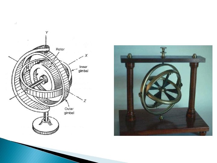
Gyroscopes A gyroscope is a device for measuring or maintaining orientation, based on the principles of conservation of angular momentum. � A mechanical gyroscope is essentially a spinning wheel or disk whose axle is free to take any orientation. This orientation changes much less in response to a given external torque than it would without the large angular momentum associated with the gyroscope's high rate of spin. Since external torque is minimized by mounting the device in gimbals, its orientation remains nearly fixed, regardless of any motion of the platform on which it is mounted. � Gyroscopes based on other operating principles also Exit, such as the electronic, microchip-packaged MEMS gyroscope devices found in consumer electronic devices, solid state ring lasers, fiber optic gyroscopes and the extremely sensitive quantum gyroscope. � Applications: navigation (INS) when magnetic compasses do not work or are not precise enough or for the stabilization of flying vehicles like radio-controlled helicopters. maintain direction in tunnel mining. �

Gyroscopes

Gyroscopic couple � Whenever a rotating body changes its axis of rotation, a couple is applied on the rotating body(shaft). This couple is known as gyroscopic couple. � Gyroscopic couple makes a change in direction of angular velocity, but the magnitude of angular velocity remains constant.

GYROSCOPIC EFFECT ON SHIP � Gyroscope is used for stabilization and directional control of a ship sailing in the rough sea. A ship, while navigating in the rough sea, may experience the following three different types of motion: � (i) Steering—The turning of ship in a curve while moving forward � (ii) Pitching—The movement of the ship up and down from horizontal position in a vertical plane about transverse axis � (iii)Rolling—Sideway motion of the ship about longitudinal axis.
 Bow – It is the fore end of ship �")
Ship Terminology � (i) Bow – It is the fore end of ship � (ii) Stern – It is the rear end of ship � (iii) Starboard – It is the right hand side of the ship looking in the direction of motion � (iv) Port – It is the left hand side of the ship looking in the direction of motion

Ship Terminology
 Left turn with clockwise rotor When ship")
Gyroscopic effect on Steering of ship (i) Left turn with clockwise rotor When ship takes a left turn and the rotor rotates in clockwise direction viewed from stern, the gyroscopic couple act on the ship is analyzed in the following way.

Left turn with clockwise rotor
 Right turn with clockwise rotor � When ship takes a right turn and")
(ii) Right turn with clockwise rotor � When ship takes a right turn and the rotor rotates in clockwise direction viewed from stern, the gyroscopic couple acts on the ship is shown in fig. � Again, the couple acts in vertical plane, means between stern and bow. Now the reaction couple tends to lower the bow of the ship and raise the stern.

Right turn with clockwise rotor
 Left turn with anticlockwise rotor � When ship takes a left turn and")
(iii) Left turn with anticlockwise rotor � When ship takes a left turn and the rotor rotates in anticlockwise direction viewed from stern, the gyroscopic couple act on the ship is shown in fig.

Left turn with anticlockwise rotor
 Right turn with anticlockwise rotor � When ship takes a right turn and")
(iv) Right turn with anticlockwise rotor � When ship takes a right turn and the rotor rotates in anticlockwise direction viewed from stern, the gyroscopic couple act on the ship is according to Fig. Now, the reaction couple tends to raise the bow of the ship and dip the stern.

Right turn with anticlockwise rotor

Gyroscopic effect chart for ship during steerin S. View point No Direction of rotor rotation Turn Effect 1 Stern Clockwise Left Bow raised Stern depressed 2 Stern Clockwise Right Bow depressed Stern raised 3 Stern Anticlockwise Left Bow depressed Stern raised 4 Stern Anticlockwise Right Bow raised Stern depressed 5 Bow Anticlockwise Left Bow raised Stern depressed 6 Bow Anticlockwise Right Bow depressed Stern raised 7 Bow Clockwise Left Bow depressed Stern raised 8 Bow Clockwise Right Bow raised Stern depressed

Gyroscopic effect on Pitching of ship � The pitching motion of a ship generally occurs due to waves which can be approximated as sine wave. During pitching, the ship moves up and down from the horizontal position in vertical plane about transverse axis.

Gyroscopic effect on Pitching of ship

Gyroscopic effect on Pitching of ship

Gyroscopic effect on Pitching of ship S. No Pitching View point Direction of rotor rotation Effect 1 Upward Stern Clockwise Ship turns towards starboard side 2 Upward Stern Anticlockwise Ship turns towards port side 3 Upward Bow Clockwise Ship turns towards port side 4 Upward Bow Anticlockwise Ship turns towards starboard side 5 Downward Stern Clockwise Ship turns towards port side 6 Downward Stern Anticlockwise Ship turns towards starboard side 7 Downward Bow Clockwise Ship turns towards starboard side 8 Downward Bow Anticlockwise Ship turns towards port side

Gyroscopic effect on Rolling of ship. � The axis of the rotor of a ship is mounted along the longitudinal axis of ship and therefore, there is no precession of this axis. Thus, no effect of gyroscopic couple on the ship frame is formed when the ship rolls.

Gyroscopic effect on Rolling of ship.
- Slides: 41