Unit V Disposal Syllabus Dumping of solid waste

Unit V Disposal Syllabus Dumping of solid waste; sanitary landfills – Site selection, design and operation of sanitary landfills – Leachate collection & treatment

Sanitary Landfill • The term ‘landfill’ is used to describe a unit operation for final disposal of ‘Municipal Solid Waste’ on land, designed and constructed with the objective of minimum impact to the environment.
 Landfilling will be done for the following types of")
Dumping of Solid wastes (a) Landfilling will be done for the following types of waste: (i) Comingled waste (mixed waste) not found suitable for waste processing; (ii) Pre-processing and post-processing rejects from waste processing sites; (iii) Non-hazardous waste not being processed or recycled. (b) Landfilling will usually not be done for the following waste streams in the municipal solid waste: (i) Bio waste/garden waste; (ii) Dry recyclables.
 Landfilling of hazardous waste stream in the municipal waste will be done at")
(c) Landfilling of hazardous waste stream in the municipal waste will be done at a hazardous waste landfill site; such a site will be identified by the State Government and is likely to be operated by industries of a district/state. (d) Landfilling of construction and demolition waste will be done in a separate landfill where the waste can be stored and mined for future use in earthwork or road projects.
 All existing and old landfills will be inspected and boreholes will be drilled")
(e) All existing and old landfills will be inspected and boreholes will be drilled for (i) recovery of leachate samples from the base of the landfill, (ii) recovery of subsoil samples beneath the base of the landfill for evaluation of permeability and soil properties and (iii) recovery of waste samples for waste characterization.
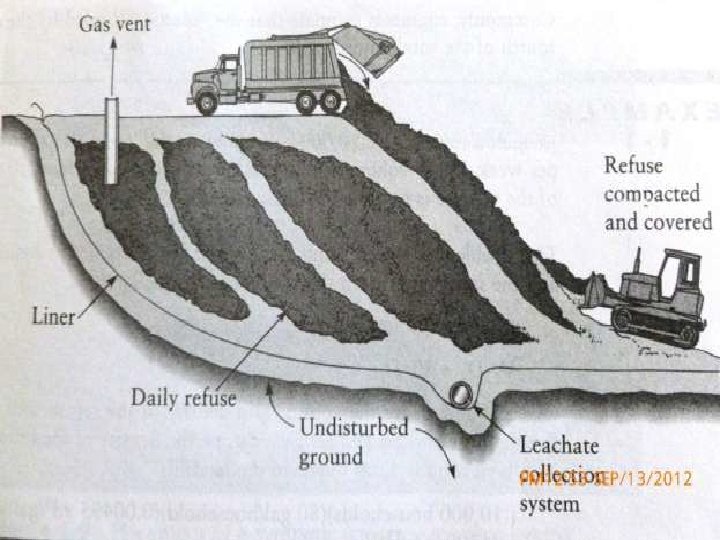

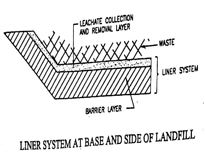
Essential Components of a Landfill • The seven essential components of a MSW landfill are: (a) A liner system at the base and sides of the landfill which prevents migration of leachate or gas to the surrounding soil. (b) A leachate collection and control facility which collects and extracts leachate from within and from the base of the landfill and then treats the leachate. (c) A gas collection and control facility (optional for small landfills) which collects and extracts gas from within and from the top of the landfill and then treats it or uses it for energy recovery.
 A final cover system at the top of the landfill which enhances surface")
(d) A final cover system at the top of the landfill which enhances surface drainage, prevents infiltrating water and supports surface vegetation. (e) A surface water drainage system which collects and removes all surface runoff from the landfill site. (f) An environmental monitoring system which periodically collects and analyses air, surface water, soil-gas and ground water samples around the landfill site. (g) A closure and post-closure plan which lists the steps that must be taken to close and secure a landfill site once the filling operation has been completed and the activities for long-term monitoring, operation and maintenance of the completed landfill.

Site selection for Landfill • Selection of a landfill site usually comprises of the following steps, when a large number (eg. 4 to 8) landfill sites are available: (i) Setting up of a locational criteria (ii) Identification of search area (iii) Drawing up a list of potential sites; (iv) Data collection (v) Selection of few best-ranked sites (vi)Environmental impact assessment and (vii)Final site selection and land acquisition.
 Lake or Pond: No landfill")
I. Locational Criteria The following criteria are suggested (a) Lake or Pond: No landfill should be constructed within 200 m of any lake or pond. (b) River: No landfill should be constructed within 100 m of a navigable river or stream. (c) Flood Plain: No landfill should be constructed within a 100 year flood plain. (d) Highway: No landfill should be constructed within 200 m of the right of way of any state or national highway.
 Habitation: A landfill site should be at least 500 m from a notified")
(e) Habitation: A landfill site should be at least 500 m from a notified habituated area. (f) Public parks: No landfill should be constructed within 300 m of a public park. (g) Critical Habitat Area: No landfill should be constructed within critical habitat areas. (h) Wetlands: No landfill should be constructed within wetlands. (i) Ground Water Table: A landfill should not be constructed in areas where water table is less than 2 m below ground surface.
 Airports: No landfill should be constructed within the limits prescribed by regulatory agencies")
(j) Airports: No landfill should be constructed within the limits prescribed by regulatory agencies (MOEF/ CPCB/ Aviation Authorities) from time to time. (k) Water Supply Well: No landfill should be constructed within 500 m of any water supply well. (l) Coastal Regulation Zone: A landfill should not be sited in a coastal regulation zone. (m) Unstable Zone: A landfill should not be located in potentially unstable zones such as landslide prone areas, fault zone etc.

II. Search Area • The search area is usually governed by the economics of waste transportation. • It is usually limited by the boundaries of the municipality. • Typically search areas are ‘search radius’ of 5 to 10 km, keeping the waste generating unit as the centre. • Alternatively, the search area a range of 5 km all around the built-up city boundary.

III. Development of a list of Potential Sites • After satisfying above 2 criteria, areas having potential for site development should be identified. • A road map may be used to show the potential sites that satisfy the locational criteria. • Preliminary data collection should be undertaken with an aim of narrowing the list of sites to a few best-ranked sites. • Areas such as abandoned quarry sites or old waste dump sites can be considered.

IV. Data Collection • Several maps and other information need to be studied to collect data within the search radius. Some are discussed below. (a) Topographic Maps: indicates low and high areas, natural surface water drainage pattern, streams, and rivers. (b) Soil Maps: shows the types of soil near the surface. (c) Land Use Plans: restrictions on the use of agricultural land or on the use of forest land for landfill purposes.
 Transportation Maps: used to determine the transportation needs in developing a site. (e)")
(d) Transportation Maps: used to determine the transportation needs in developing a site. (e) Flood Plain Maps: Landfill siting must be avoided within the flood plains of major rivers. (f) Ground Water Maps, (i) Rainfall Data (j) Wind Map (k) Seismic Data

V. Site Walk-over & Establishment of Ground Truths • A site reconnaissance will be conducted by a site walk-over as a part of the preliminary data collection. • All features observed in various maps will be confirmed. • Additional information pertaining to the following will be ascertained from nearby inhabitants: (a) Flooding during monsoons (b) Soil Type (c) Depth to G. W. Table (as observed in open wells or tube wells) (d) Quality of groundwater and (e) Depth to bedrock.

VI. Preliminary Boreholes and Geophysical Investigation • At each site one to two boreholes will be drilled and samples collected at every 1. 5 m interval to a depth of 20 m below the ground surface. • The following information will be obtained: (i) Soil type and stratification (ii) Permeability of each stratum (iii) Strength and compressibility parameters (optional) (iv) Ground water level and quality and (v) Depth to bedrock.

VII. Assessment of Public Reaction • A preliminary assessment of public opinion regarding all the potential sites in the list is essential. • Public reaction is less hostile if landfilling is done in an area already degraded by earlier municipal waste dumps or other activities such as quarrying, ash disposal etc.

VIII. Selection of Few Best-Ranked Sites • From amongst a large number of sites, the selection of a final site will emerge from a two -stage approach. (a) Selection of a few best-ranked sites (usually 2 sites, sometimes 3) (b) Selection of final site on the basis of environmental impact assessment, social acceptance and cost of disposal.
 • Wherever feasible, environmental impact assessment will be conducted")
IX. Environmental Impact Assessment (EIA) • Wherever feasible, environmental impact assessment will be conducted for two alternate sites (in exceptional circumstances up to 3 sites) • The impact of the landfill on the following will be quantified: (a) Ground water quality; (b) Surface water quality; (c) Air quality – gases, dust, litter; (d) Aesthetics – visual, vermin, flies; (e) Noise; (f) Land use alteration; (g) Traffic alteration; (h) Drainage alteration; (i) Soil erosion; (j) Ecological impacts

X. Final Site Selection • The final selection of the site from amongst the best-ranked alternatives should be done by comparing: (a) The environmental impact; (b) Social acceptance; and (c) Transportation and landfilling costs.

Design of Landfill • Design of a landfill can be described through following aspects Design Life • A landfill design life will comprise of an ‘active’ period an ‘closure and post-closure’ period. • The ‘active’ period may typically range from 10 to 25 years depending on the availability of land area. • The ‘closure and post-closure’ period for which a landfill will be monitored and maintained will be 25 years after the ‘active period’ is completed.

Waste Volume and Landfill Capacity • The volume of waste to be placed will be computed for the ‘active’ period of the landfill taking into account (a) the current generation of waste per annum and (b) the anticipated increase in rate of waste generation on the basis of past records or population growth rate. • The actual capacity of the landfill will depend upon the volume occupied by the liner system and the cover material (daily, intermediate and final cover) as well as the compacted density of the waste.

• In addition, the amount of settlement a waste will undergo due to overburden stress and due to biodegradation should also be taken into account. • Densities may range as low as 0. 40 t/cu. m. to 1. 25 t/cu. m. • For planning purposes, a density of 0. 85 t/cu. m. may be adopted for biodegradable wastes with higher values (typically 1. 1 t/cu. m. ) for inert waste.

• The total landfill area should be approximately 15% more than the area required for landfilling to accommodate all infrastructure and support facilities as well as to allow the formation of a green belt around the landfill. • There is no standard method for classifying landfills by their capacity. However the following nomenclature is often observed in literature: Small size landfill : less than 5 hectare area Medium size landfill : 5 to 20 hectare area Large size landfill : >20 hectare area • Landfill heights are reported to vary from less than 5 m to well above 30 m.

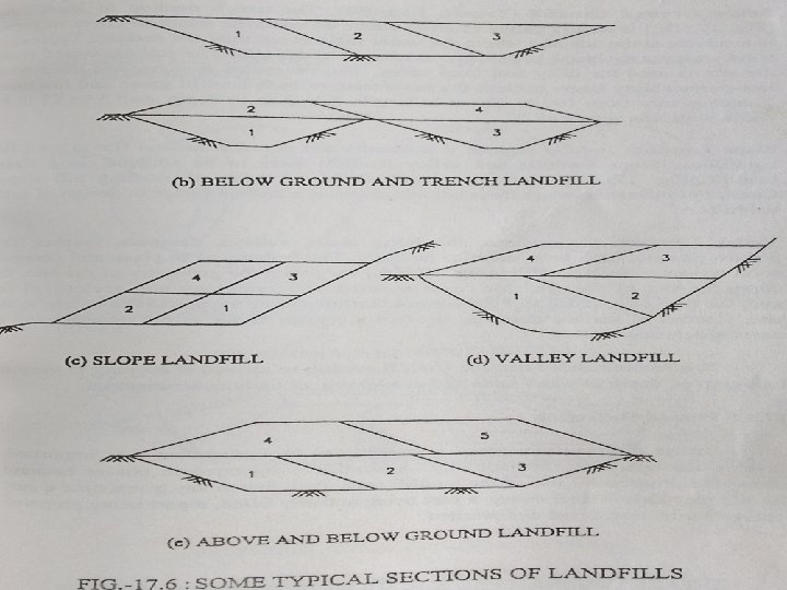
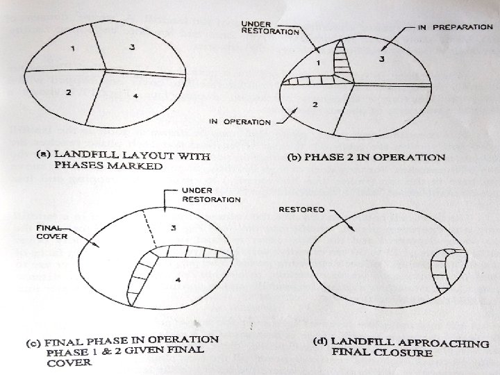
Layout • A landfill site will comprise of the area in which the waste will be filled as well as additional area for support facilities. • Within the area to be filled, work may proceed in phases with only a part of the area under active operation. • The following facilities must be located in the layout: (a) Access roads (b) Equipment shelters (c) Weighing scales
 Office space (e) Location of waste inspection and transfer station (if used) (f)")
(d) Office space (e) Location of waste inspection and transfer station (if used) (f) Temporary waste storage and/or disposal sites for special wastes (g) Areas to be used for waste processing (e. g. shredding) (h) Areas for stockpiling cover material and liner material (i) Drainage facilities (j) Location of landfill gas management facilities (k) Location of leachate treatment facilities; and (l) Location of monitoring wells.

A typical site layout

A typical section of Landfill

Operation of a Landfill • To secure public acceptability, landfill operations require careful planning and determination of the extent of environmental effects. • The basic factor influencing the planning of site operations is the nature and quantity of incoming waste.

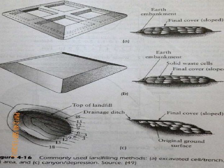
• The various aspects of operation of a landfill are as follows 1. Methods of Filling • Trench Method: This involves the excavation of a trench into which waste is deposited, and the excavated material is then used as cover. • Area Method: Wastes may be deposited in layers and so form terraces over the available area. However, with this type of operation, excessive leachate generation may occur.

• Cell Method: This method involves the deposition of wastes within preconstructed bounded area. • It is now the preferred method in the industrialized world, since it encourages the concept of progressive filling and restoration. • Canyon / Depression: This method refers to the placing of suitable wastes against lined canyon or ravine slide slopes. • Slope stability and leachate gas emission are critical issues for this type of waste placement.

2. Refuse Placement • The working space should to permit vehicles to move and unload quickly and safely without refuse spreading, and allow easy operation of the site equipment. • Depositing waste in thin layers using a compactor, a high waste density to be achieved.

3. Covering of Waste • At the end of each working day, all exposed surfaces, including the sides and working space, should be covered with a suitable inert material to a depth of at least 15 cm. • This daily cover is considered essential, as it minimizes windblown litter and helps reduce odours.

4. Site Equipment and Workforce Orientation • The equipment most commonly used on landfill sites includes steel wheeled compactors, tracked dozers, loaders, earthmovers and hydraulic excavators. • Scrapers are used for excavating and moving cover materials. • In addition to appropriate equipment, proper training must be ensured for the workforce.

5. Leachate / gas Monitoring • Monitoring of leachate plays a vital role in the management of landfills. • Data on the volume of leachate and their composition are essential for proper control of leachate generation and its treatment.

6. Groundwater Monitoring • A continued groundwater monitoring programme for confirming the integrity of the liner system is essential. • At an early stage of site preparation, a number of monitoring boreholes need to be provided around the site. • However, the location, design and number of boreholes depend on the size of the landfill, proximity to an aquifer, geology of the site and types of wastes deposited.

Leachate Collection & Treatment Leachate Control • Leachate control within a landfill involves the following steps: (a) Prevention of migration of leachate from landfill sides and landfill base to the subsoil by a suitable liner system (b) Drainage of leachate collected at the base of a landfill to the sides of the landfill and removal of the leachate from within the landfill.

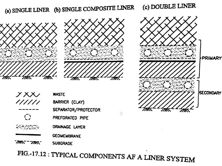
• Three types of liner systems are usually adopted and these are described hereafter: (a) Single Liner System: Such a system comprises of a single primary barrier overlain by a leachate collection system with an appropriate separation/protection layer. A system of this type is used for a low vulnerability landfill. (b) Single Composite Liner System: A composite liner comprises of two barriers, made of different materials, placed in intimate contact with each other to provide a beneficial combined effect of both the barriers. Usually a flexible geo membrane is placed over a clay or amended soil barrier.
 Double Liner System: • In a double liner system a single liner system")
(c) Double Liner System: • In a double liner system a single liner system is placed twice, one beneath the other. The top barrier (called the primary barrier) is overlaid by a leachate collection system. Beneath the primary barrier, another leachate collection system (often called the leak detection layer) is placed followed by a second barrier (the secondary barrier).

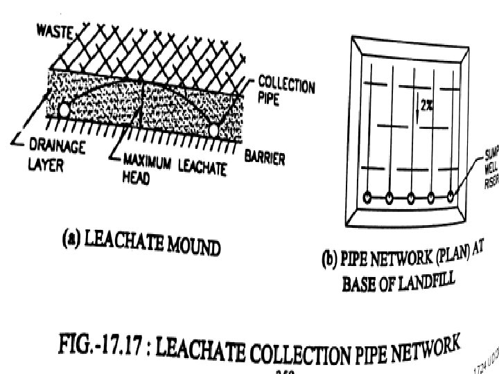
Leachate Collection • A leachate collection system comprises of a drainage layer, a perforated pipe collector system, sump collection area, and a removal system. • The leachate drainage layer is usually 30 cm thick, has a slope of 2% or higher and a permeability of greater than 0. 01 cm/sec. • A system of perforated pipes and sumps are provided within the drainage layer.
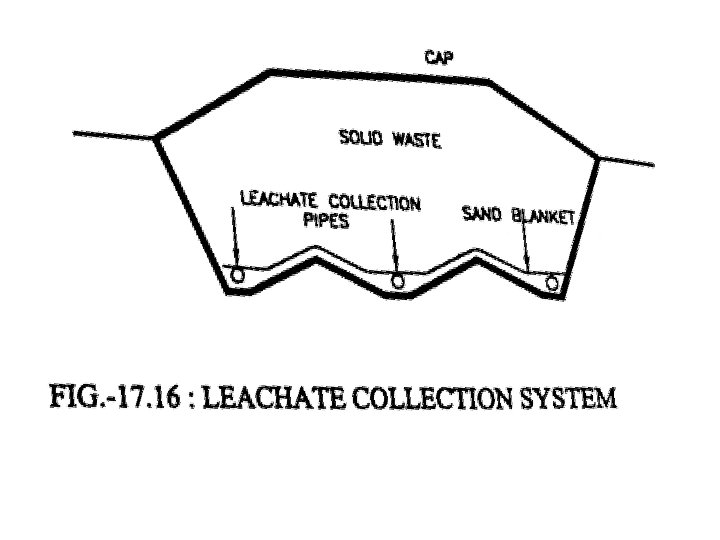
 pumping in vertical wells")
• Leachate is removed from the landfill by (a) pumping in vertical wells or chimneys, (b) pumping in side slope risers, or (c) by gravity drains rough the base of a landfill in above -ground and sloped landfills.
 Finalization of layout pipe")
The design steps for the leachate collection system are: (a) Finalization of layout pipe network and sumps in conjunction with drainage layer slopes of 2% (b) Estimation of pipe diameter and spacing on the basis of estimated leachate quantity and maximum permissible leachate head (c) Estimating the size of sumps and pump (d) Design of wells/side slopes risers for leachate removal; and (e) Design of a holding tank.
 Discharge to Lined Drains: This option is usually not feasible. It")
Leachate Treatment (a) Discharge to Lined Drains: This option is usually not feasible. It can only be adopted if the leachate quality is shown to satisfy all waste water discharge standards for lined drains, consistently for a period of several years. (b) Discharge To Waste Water Treatment System: For landfills close to a waste water treatment plant, leachate may be sent to such a plant after some pretreatment. Reduction of organic content is usually required as a pretreatment.
 Recirculation: One of the methods for treatment of leachate is to recirculate it")
(c) Recirculation: One of the methods for treatment of leachate is to recirculate it through the landfill. This has two beneficial effects: (i) The process of landfill stabilization is accelerated (ii) The constituents of the leachate are attenuated by the biological, chemical and physical changes occurring with the landfill. • Recirculation of a leachate requires the design of a distribution system to ensure that the leachate passes uniformly throughout the entire waste.
 Evaporation of Leachate: one of the techniques used to manage leachate is to")
(d) Evaporation of Leachate: one of the techniques used to manage leachate is to spray it in lined leachate ponds and allow the leachate to evaporate. • Such ponds have to be covered with geo membranes during the high rainfall periods. • The leachate is exposed during the summer months to allow evaporation. • Odour control has to be exercised at such ponds. (e) Treatment of Leachate: The types of treatment facilities to be used depend upon the leachate characteristics.

• Typically, treatment may be required to reduce the concentration of the following prior to discharge: • Degradable and non-degradable organic materials, • Specific hazardous constituents, Ammonia and nitrate ions, Sulphides, Odorous compounds, and Suspended solids.

• Treatment processes may be biological processes (such as activated sludge, aeration, nitrification (dentrification), • chemical processes (such as oxidation, neutralisation) and • physical processes (such as air stripping, activated adsorption, ultra filtration etc. ). • The treated leachate may be discharged to surface water bodies.
- Slides: 56