Unit No 5 Measuring and control of Harmonics


. ■ ISC")


- Slides: 101
Unit No. 5 Measuring and control of Harmonics BE Electrical Power Quality Mr. Hadpe S. S. Asst. Professor Electrical Engineering Department Matoshri College of Engineering and Research Centre Nashik.
Syllabus: Concept of point of common coupling and harmonic evaluation, principles of controlling harmonics, Harmonic study procedures and computer tools for harmonic analysis, Devices for controlling harmonic distortion design of filters for harmonic reduction.
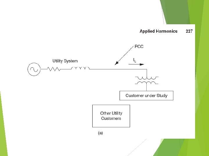
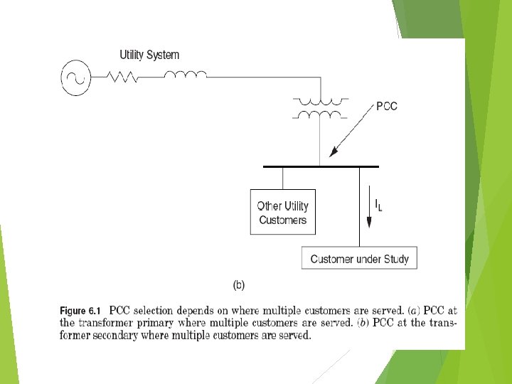
Concept of point of common coupling Evaluations of harmonic distortion are usually performed at a point between the end user or customer and the utility system where another customer can be served. This point is known as the point of common coupling. The PCC can be located at either the primary side or the secondary side of the service transformer depending on whether or not multiple customers are supplied from the transformer. In other words, if multiple customers are served from the primary of the transformer, the PCC is then located at the primary. On the other hand, if multiple customers are served from the secondary of the transformer, the PCC is located at the secondary.
Harmonic evaluations on the utility system involve procedures to determine the acceptability of the voltage distortion for all customers. IEEE Standard 519 -1992 provides guidelines for acceptable levels of voltage distortion on the utility system. Note that the recommended limits are specified for the maximum individual harmonic component and for the THD.
There are two important components for limiting voltage distortion levels on the overall utility system: 1. Harmonic currents injected from individual end users on the system must be limited. These currents propagate toward the supply source through the system impedance, creating voltage distortion. Thus by limiting the amount of injected harmonic currents, the voltage distortion can be limited as well. This is indeed the basic method of controlling the overall distortion levels proposed by IEEE Standard 519 -1992.
2. The overall voltage distortion levels can be excessively high even if the harmonic current injections are within limits. This condition occurs primarily when one of the harmonic current frequencies is close to a system resonance frequency. This can result in unacceptable voltage distortion levels at some system locations. The highest voltage distortion will generally occur at a capacitor bank that participates in the resonance. This location can be remote from the point of injection.
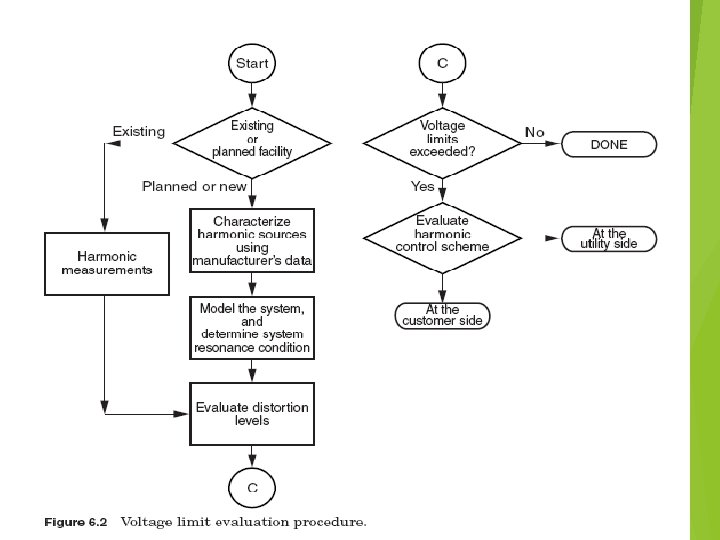
Voltage limit evaluation procedure at utility side 1. Characterization of harmonic sources.
Harmonic evaluation for end-user facilities Harmonic problems are more common at end-user facilities than on the utility supply system. Most nonlinear loads are located within end-user facilities, and the highest voltage distortion levels occur close to harmonic sources. The most significant problems occur when there are nonlinear loads and power factor correction capacitors that result in resonant conditions.
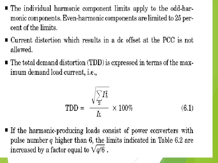
IEEE Standard 519 -1992 Current Limits
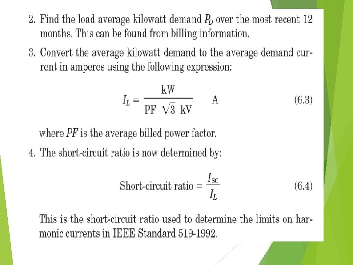
■ Ih is the magnitude of individual harmonic components (rms amps). ■ ISC is the short-circuit current at the PCC. ■ IL is the fundamental component of the maximum demand load current at the PCC. It can be calculated as the average of the maximum monthly demand currents for the previous 12 months or it may have to be estimated.
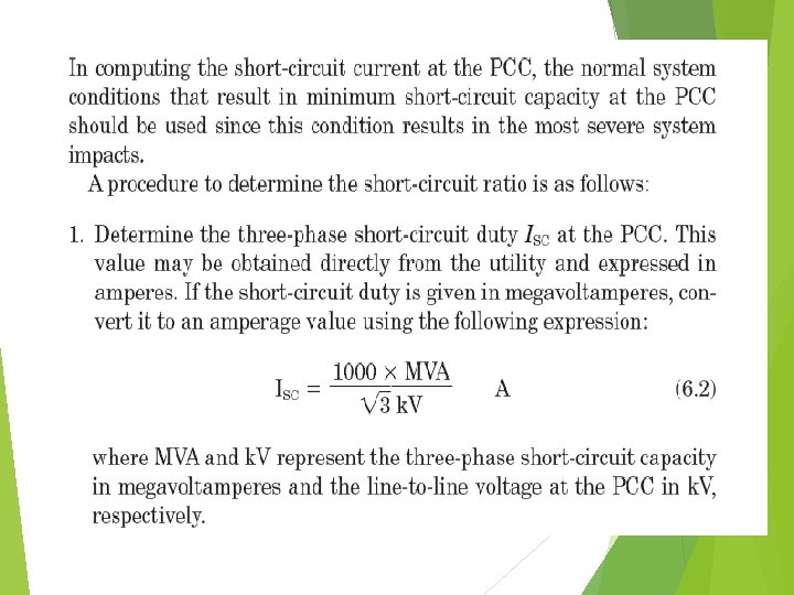
Current limit evaluation procedure This procedure involves evaluation of the harmonic generation characteristics from individual end-user loads with respect to IEEE Standard 519 -1992 limits. However, special consideration is required when considering power factor correction equipment. 1. Define the PCC. For industrial and commercial end users, the PCC is usually at the primary side of a service transformer supplying the facility. 2. Calculate the short-circuit ratio at the PCC and find the corresponding limits on individual harmonics and on the TDD.
3. Characterize the harmonic sources. Individual nonlinear loads in the facility combine to form the overall level of harmonic current generation. The best way to characterize harmonic current in an existing facility is to perform measurements at the PCC over a period of time (at least 1 week). For planning studies, the harmonic current can be estimated knowing the characteristics of individual nonlinear loads and the percentage of the total load made up by these nonlinear loads.
4. Evaluate harmonic current levels with respect to current limits using Table 6. 2. If these values exceed limits, the facility does not meet the limit recommended by IEEE Standard 519 -1992 and mitigation may be required.
Principles for Controlling Harmonics Harmonic distortion is present to some degree on all power systems. Fundamentally, one needs to control harmonics only when they become a problem. There are three common causes of harmonic problems: 1. The source of harmonic currents is too great. 2. The path in which the currents flow is too long (electrically), resulting in either high voltage distortion or telephone interference. 3. The response of the system magnifies one or more harmonics to a greater degree than can be tolerated.
When a problem occurs, the basic options for controlling harmonics are: 1. Reduce the harmonic currents produced by the load. 2. Add filters to either siphon the harmonic currents off the system, block the currents from entering the system, or supply the harmonic currents locally. 3. Modify the frequency response of the system by filters, inductors, or capacitors.
1. Reducing harmonic currents in loads There is often little that can be done with existing load equipment to significantly reduce the amount of harmonic current it is producing unless it is being misoperated. While an overexcited transformer can be brought back in into normal operation by lowering the applied voltage to the correct range, arcing devices and most electronic power converters are locked into their designed characteristics. Adding a line reactor or transformer in series will significantly reduce harmonics, as well as provide transient protection benefits.
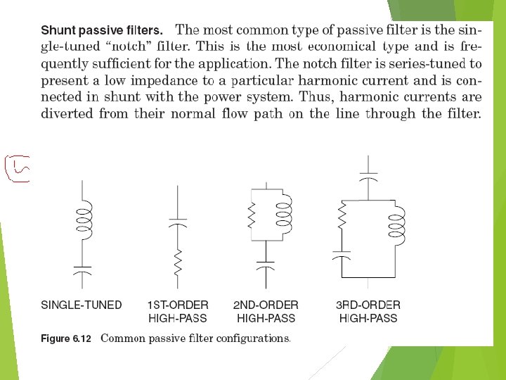
2. Filtering The shunt filter works by short-circuiting harmonic currents as close to the source of distortion as practical. This keeps the currents out of the supply system. This is the most common type of filtering applied because of economics and because it also tends to correct the load power factor as well as remove the harmonic current. Another approach is to apply a series filter that blocks the harmonic currents. This is a parallel-tuned circuit that offers a high impedance to the harmonic current. It is not often used because it is difficult to insulate and the load voltage is very distorted.
3. Modifying the system frequency response There a number of methods to modify adverse system responses to harmonics: 1. Add a shunt filter. Not only does this shunt a troublesome harmonic current off the system, but it completely changes the system response, most often, but not always, for the better. 2. Add a reactor to detune the system. Harmful resonances generally occur between the system inductance and shunt power factor correction capacitors. The reactor must be added between the capacitor and the supply system source. One method is to simply put a reactor in series with the capacitor to move the system resonance without actually tuning the capacitor to create a filter. Another is to add reactance in the line.
3. Change the capacitor size. This is often one of the least expensive options for both utilities and industrial customers. 4. Move a capacitor to a point on the system with a different short-circuit impedance or higher losses. This is also an option for utilities when a new bank causes telephone interference— moving the bank to another branch of the feeder may very well resolve the problem. This is frequently not an option for industrial users because the capacitor cannot be moved far enough to make a difference.
Harmonic Studies Harmonic studies play an important role in characterizing and understanding the extent of harmonic problems. Harmonic studies are often performed when 1. Finding a solution to an existing harmonic problem 2. Installing large capacitor banks on utility distribution systems or industrial power systems 3. Installing large nonlinear devices or loads 4. Designing a harmonic filter 5. Converting a power factor capacitor bank to a harmonic filter.
Harmonic study procedure The ideal procedure for performing a power systems harmonics study can be summarized as follows: 1. Determine the objectives of the study. This is important to keep the investigation on track. For example, the objective might be to identify what is causing an existing problem and solve it. Another might be to determine if a new plant expansion containing equipment such as adjustable-speed drives and capacitors is likely to have problems. 2. If the system is complex, make a pre measurement computer simulation based on the best information available. Measurements are expensive in terms of labor, equipment, and possible disruption to plant operations. It will generally be economical to have a good idea what to look for and where to look before beginning the measurements.
3. Make measurements of the existing harmonic conditions, characterizing sources of harmonic currents and system bus voltage distortion. 4. Calibrate the computer model using the measurements. 5. Study the new circuit condition or existing problem. 6. Develop solutions (filter, etc. ) and investigate possible adverse system interactions. Also, check the sensitivity of the results to important variables. 7. After the installation of proposed solutions, perform monitoring to verify the correct operation of the system.
Admittedly, it is not always possible to perform each of these steps ideally. The most often omitted steps are one, or both, measurement steps due to the cost of engineering time, travel, and equipment charges. An experienced analyst may be able to solve a problem without measurements, but it is strongly recommended that the initial measurements be made if at all possible because there are many unpleasant surprises lurking in the shadows of harmonics analysis.
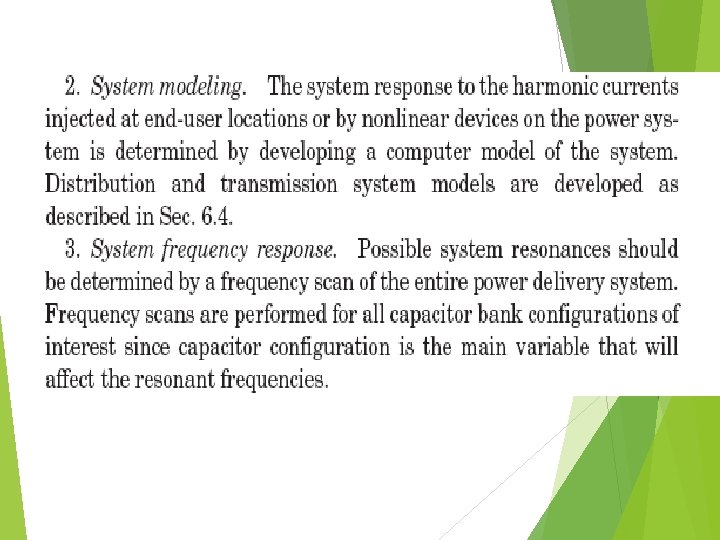
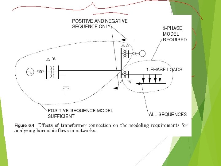
Developing a system model There are two fundamental issues that need to be considered in developing a system model for harmonic simulation studies. The first issue is the extent of the system model to be included in the simulation. Secondly, one must decide whether the model should be represented as a singlephase equivalent or a full three-phase model.
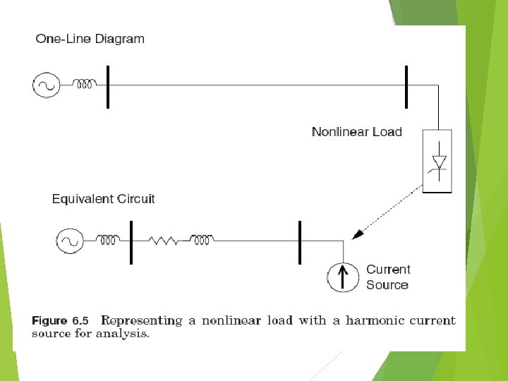
Modeling harmonic sources Most harmonic flow analysis on power systems is performed using steady-state, linear circuit solution techniques. Harmonic sources, which are nonlinear elements, are generally considered to be injection sources into the linear network models. They can be represented as current injection sources or voltage sources.
Computer tools for harmonics analysis To use the computer tools commonly available, the analyst must describe the circuit configuration, loads, and the sources to the program. Data that must be collected include ■ Line and transformer impedances ■ Transformer connections ■ Capacitor values and locations (critical) ■ Harmonic spectra for nonlinear loads ■ Power source voltages These values are entered into the program, which automatically adjusts impedances for frequency and computes the harmonic flow throughout the system.
Today, most power system harmonics analysis is performed in the sinusoidal steady state using computer programs specially developed for the purpose. Prior to the widespread use of computers for harmonics analysis, power systems harmonic studies were frequently performed on analog simulators such as a transient network analyzer (TNA). The few TNAs in the United States in the mid-1970 s were located at large equipment manufacturers, primarily at General Electric Co. , Westinghouse Electric, and Mc. Graw-Edison Power Systems.
In 1975, when author Dugan, then with Mc. Graw. Edison, constructed the first electronic arc model for a TNA to eliminate the need to use the second source. In that same year, to overcome the limitations of harmonic analysis by analog simulator, Dugan teamed up with Dr. Sarosh N. Talukdar and William L. Sponsler at Mc. Graw-Edison to develop one of the first commercial computer programs specifically designed to automate analysis of harmonic flows on large-scale power systems. Dubbed the Network Frequency Response Analysis Program (NFRAP), it was developed for the Virginia Electric Power Company to study the impacts of adding 220 -k. V capacitor banks on the transmission system. These were someof the first capacitors applied at this voltage level.
From 1977 to 1979, EPRI sponsored an investigation of harmonics on utility distribution feeders. 5, 6 One of the products of this research was the Distribution Feeder Harmonics Analysis program. Erich W. Gunther recoded the algorithms in the Pascal language and created the V-HARM program. 7 To our knowledge, this was the first commercial harmonic analysis program written expressly for the PC environment. Gunther subsequently has written the latest generation in this heritage of harmonic analysis tools in the C language for the Microsoft Windows environment. It is called the Super. Harm program and can be licensed from Electrotek Concepts, Inc.
Of course, harmonics problems can be solved on electromagnetic transients analysis programs such as the EMTP, originally developed by the Bonneville Power Administration. Another one is the PSCAD/EMTDC program from the Manitoba HVDC Research Centre. Recently MATLAB program in the simulink also most prefer for the harmonic study by interfacing physical system to simulation model.
Devices for Controlling Harmonic Distortion As described in Sec. 6. 2, a simple mitigation action such as adding, resizing, or relocating a shunt capacitor bank can effectively modify an unfavorable system frequency response, and thus bring the harmonicdistortion to an acceptable level. Similarly, a reactor can perform the same function by detuning the system off harmful resonances.
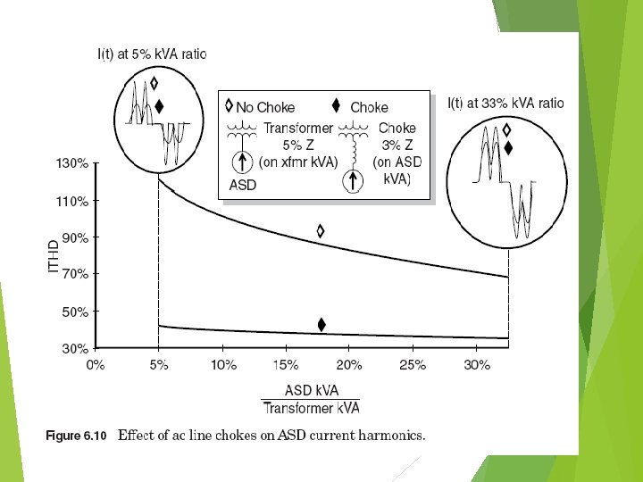
1. In-line reactors or chokes A simple, but often successful, method to control harmonic distortion generated by adjustable-speed drives involves a relatively small reactor, or choke, inserted at the line input side of the drive. This is particularly effective for PWM-type drives. The inductance slows the rate at which the capacitor on the dc bus can be charged and forces the drive to draw current over a longer time period. The net effect is a lower-magnitude current with much less harmonic content while still delivering the same energy.
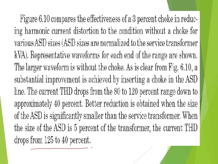
A typical 3 percent input choke can reduce the harmonic current distortion for a PWM-type drive from approximately 80 to 40 percent. This impressive harmonic reduction is illustrated in Fig. 6. 8. Additional harmonic reduction is rather limited when the choke size is increased beyond 3 percent. The choke size is computed on the drive k. VA base.
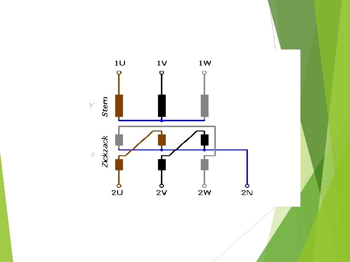
2. Zigzag transformer A zigzag transformer is a special-purpose transformer with a Zigzag or "interconnected star" winding connection, such that each output is the vector sum of two (2) phases offset by 120°. It is used as a grounding transformer creating a missing neutral connection from an ungrounded 3 -phase system to permit the grounding of that neutral to an earth reference point ; to perform harmonic mitigation, as they can suppress triplet (3 rd, 9 th, 15 th, 21 st, etc. ) harmonic currents; [2] to supply 3 -phase power as an autotransformer (serving as the primary and secondary with no isolated circuits); [3] and to supply non-standard, phase-shifted, 3 phase power.
Zigzag transformers are often applied in commercial facilities to control zero-sequence harmonic components. A zigzag transformer acts like a filter to the zero-sequence current by offering a low-impedance path to neutral. This reduces the amount of current that flows in the neutral back toward the supply by providing a shorter path for the current. To be effective, the transformer must be located near the load on the circuit that is being protected.
3. Passive filters are inductance, capacitance, and resistance elements configured and tuned to control harmonics. They are commonly used and are relatively inexpensive compared with other means for eliminating harmonic distortion.
To avoid problems with this resonance, filters are added to the system starting with the lowest significant harmonic found in the system. Placing a reactor in the neutral of a capacitor is a common way to force the bank to filter only zero-sequence harmonics. This technique is often employed to eliminate telephone interference. A tapped reactor is installed in the neutral and the tap adjusted to minimize the telephone.
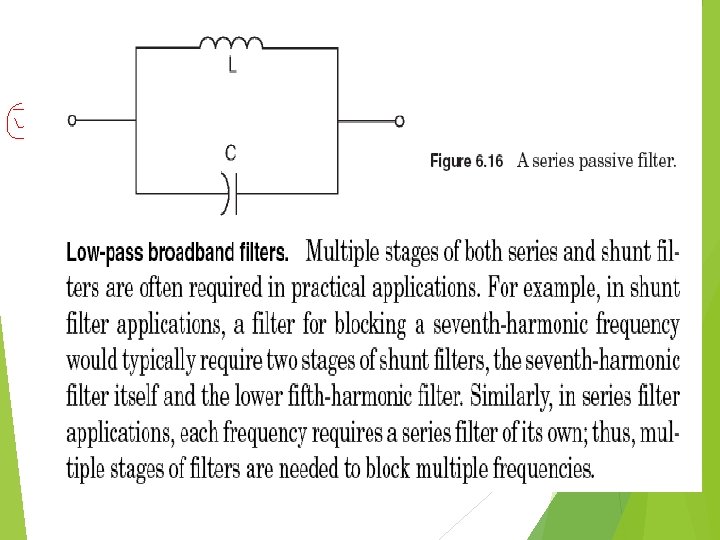
Series passive filters. Unlike a notch filter which is connected in shunt with the power system, a series passive filter is connected in series with the load. The inductance and capacitance are connected in parallel and are tuned to provide a high impedance at a selected harmonic frequency. The high impedance then blocks the flow of harmonic currents at the tuned frequency only. At fundamental frequency, the filter would be designed to yield a low impedance, thereby allowing the fundamental current to follow with only minor additional impedance and losses. Figure 6. 16 shows a typical series filter arrangement.
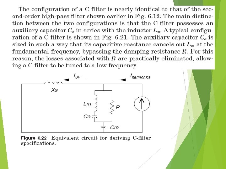
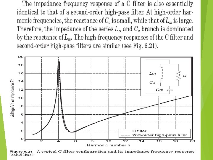
C filters are an alternative to low-pass broadband filters in reducing multiple harmonic frequencies simultaneously in industrial and utility systems. They can attenuate a wide range of steadystate and time-varying harmonic and interharmonic frequencies generated by electronic converters, induction furnaces cycloconverters, and the like.
Active filters are relatively new types of devices for eliminating harmonics. They are based on sophisticated power electronics and are much more expensive than passive filters. However, they have the distinct advantage that they do not resonate with the system.
The basic idea is to replace the portion of the sine wave that is missing in the current in a nonlinear load. Figure 6. 25 illustrates the concept. An electronic control monitors the line voltage and/or current, switching the power electronics very precisely to track the load current or voltage and force it to be sinusoidal. As shown, there are two fundamental approaches: one that uses an inductor to store current to be injected into the system at the appropriate instant and one that uses a capacitor. Therefore, while the load current is distorted to the extent demanded by the nonlinear load, the current seen by the system is much more sinusoidal. Active filters can typically be programmed to correct for the power factor as well as harmonics.
Harmonic Filter Design: A Case Study This section illustrates a procedure for designing harmonic filters for industrial applications. This procedure can also be used to convert an existing power factor correction capacitor into a harmonic filter. power factor correction capacitors are used widely in industrial facilities to lower losses and utility bills by improving power factor. On the other hand, power factor correction capacitors may produce harmonic resonance and magnify utility capacitorswitching transients. Therefore, it is often desirable to implement one or more capacitor banks in a facility as a harmonic filter.
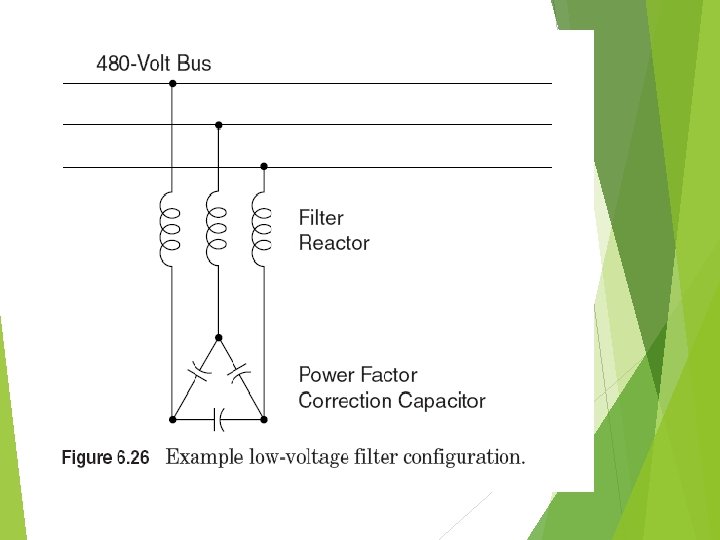
System Description A single-tuned notch filter will be designed for an industrial facility and applied at a 480 -V bus. The load where the filter will be installed is approximately 1200 k. VA with a relatively poor displacement power factor of 0. 75 lagging. The total harmonic current produced by this load is approximately 30 percent of the fundamental current, with a maximum of 25 percent fifth harmonic. The facility is supplied by a 1500 - k. VA transformer with 6. 0 percent of impedance. The fifth-harmonic background voltage distortion on the utility side of the transformer is 1. 0 percent of the fundamental when there is no load. Figure 6. 7 shown earlier depicts the industrial facility where the filter will be applied. The harmonic design procedures are provided in the following steps.
1. Select a tuned frequency for the filter. The tuned frequency is selected based on the harmonic characteristics of the loads involved. Because of the nature of a single-tuned filter, the filtering should start at the lowest harmonic frequency generated by the load. In this case, that will be the fifth harmonic. The filter will be tuned slightly below the harmonic frequency of concern to allow for tolerances in the filter components and variations in system impedance. This prevents the filter from acting as a direct short circuit for the offending harmonic current, reducing duty on the filter components. It also minimizes the possibility of dangerous harmonic resonance should the system parameters change and cause the tuning frequency to shift.
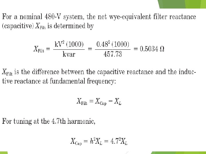
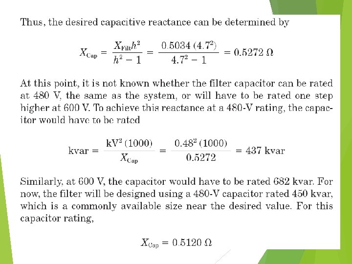
2. Compute capacitor bank size and the resonant frequency. As a general rule, the filter size is based on the load reactive power requirement for power factor correction. When an existing power factor correction capacitor is converted to a harmonic filter, the capacitor size is given. The reactor size is then selected to tune the capacitor to the desired frequency. However, depending on the tuned frequency, the voltage rating of the capacitor bank may have to be higher than the system voltage to allow for the voltage rise across the reactor. Therefore, one may have to change out the capacitor anyway.
This example assumes that no capacitor is installed and that the desired power factor is 96 percent. Thus, the net reactive power from the filter required to correct from 75 to 96 percent power factor can be computed as follows: