UNIT IV SUPER STRUCTURECONSTRUCTION SYNOPSIS v Launching girders


 is a tall habitable building. Emporis data committee defines skyscraper")


- Slides: 53
UNIT IV SUPER STRUCTURECONSTRUCTION
SYNOPSIS: v. Launching girders v. Bridge decks v. Offshore platforms v. Special forms for shells § Braced domes and § Space decks v. High Rise Structures v. Material handling v. Transmission Tower v. Sky Scrapper v. Cooling Tower v. Erecting light weight components on tall structures v. Support structure for heavy equipments and conveyors v. Erection of articulated structures
SITE ERECTION METHODS Slide Slowing Method A method of construction of the super structure is to erect girders, whether steel or precast concrete girders, over temporary supports by the side of the pier, opposite to the span and when ready, slewing same into position. Move the unit, full or part of the deck, if any, is added after the basic girder structure with adequate bracings is slewed in This method is adopted when the erection or casting of the girders is being done simultaneously with the construction of the piers as in new construction, in order to avoid delay later Where pier height is too much it is adopted and in existing bridges case, this method is adopted to replace the existing structure with stronger unit
Common for both railway and road bridges but one difference is deck, except for linking of rails in case of railway bridges and weathering course & parapet in case of road bridges For new bridges the staging for casting will have to be put up by the side of the piers on one side In case of replacement, similar staging will have to be erected on the other side also for receiving the old girders and dismantling them into parts before being taken away to stores In both cases, some temporary arrangements over the piers or adjacent to them in the alignment for the purpose of slewing in will also be necessary
LAUNCHING METHODS End Launching This method is adopted mainly for long span prestressed concrete and steel girders and mostly on new construction The girder is cast or built up on the approach bank, and it is longitudinally traversed over the opening it has to span and lowered in position For this purpose, a small temporary intermediate staging has to be provided in the gap between piers for taking the girder across the gap For steel girder bridges , staging are arrange them one behind the other, linked with temporary links and launch them together
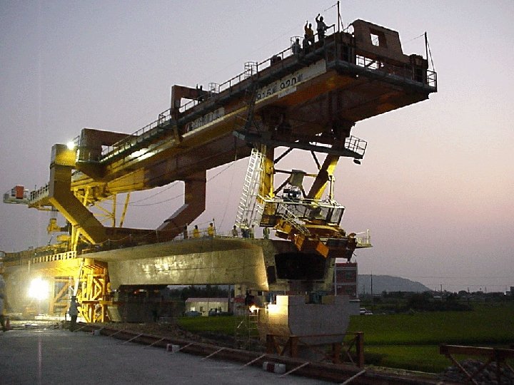
Launching Girders Fully cast prestressed concrete girders are not launched independently as the cantilevering stress developed is considerable and the design difficult The method adopted is to first launch a steel or aluminium supporting frame or girder so that it spans over the gap Once the launching of this girder over the gap on one side is over, the first main girder is moved over this temporary girder or frame, supported at intervals or pulled across When the full length of the main girder has come over the span, it is jacked up and temporarily held in position and the launching girder can be side – slewed to take the position of the next girder over the span.
The main girder launched earlier is then lowered into position with the helps of jacks The next girder cast and ready on the approach is then launched longitudinally over the temporary girder again and the process repeated till all the permanent girders are put in position The launching girder can then be moved over to the next span and it can take the position required for taking on the first girder of the next span The girders of the next span can then be longitudinally taken over the girders erected in the previous span and then over the temporary girder on the next span and the process repeated
Erection of Concrete Girders with Cranes/ Derrick If the bed is dry, the girders can be cast on the bed by the side of the span and they can be erected by using two mobile cranes one on either and with the help of a suitable derrick in the centre or one derrick each on either end If the height of the pier is not much and girders are too heavy to be handled by the available crane or derrick, the girder can be jacked up from either end on temporary trestles to pier top level and then side – slewed in position launched and slewed has the minimum weight The full deck slab can be cast subsequently In the case of prestressed concrete girders there will be transverse prestressing also involved
The diaphragm with necessary ducting should be cast after all the girders are launched correctly and adjusted in position Part prestressing is done before individual girders are lifted or launched and remaining cables are tensioned, some before and balance after or all after the deck is cast according to the design This stage prestressing is done to take the maximum advantage of prestressing In doing such post – tensioning, extreme care has to be exercised in following the sequence that has been given by the designers and any small change can cause a crack in the system or unwanted lateral deflection in the individual girder
Cantilevering Method For very large spans, the method which is now used is the cantilevering method In this method, the erection starts from the abutment end and the erection of the members ahead is done by using a crane which travels on the top boom of the previously erected part of the structure in case of steel and by using the support on the previously erected part structure in case of prestressed concrete construction Types : Howrah Bridge – Steel cantilevers Sydney Harbour Bridge – Steel arch Second Godavari Bridge – Steel simply supported
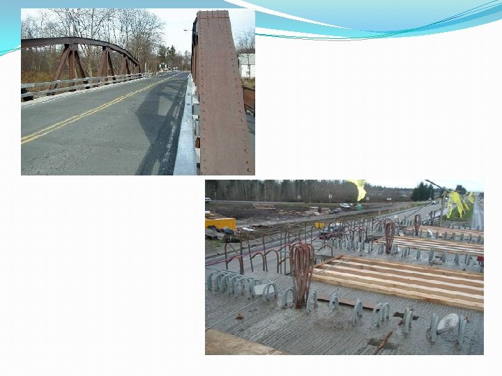
BRIDGE DECKS The grade line of highway or railway track and the clearance required under the bridge decide the use of deck type or through type bridge Incase the sufficient clearance is unavailable under the bridge, the deck type bridges are the advantages over the through type bridges The deck type bridges are relative economical The height of piers and abutments are reduced in the deck type bridges
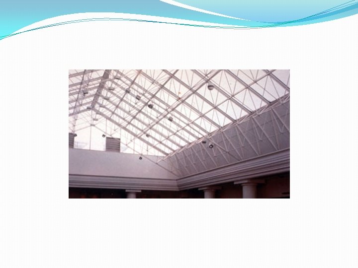
SPACE DECKS Of recent years a range on standard section mild steel tubes has been manufactured in increasing quantity. The advantages of a tubular section are that it has a uniform cross section and its position does not have to be adjusted for maximum strength as does an angle section and the surface area of a tubular section is considerably less than standard tubular sections welded together. Erection of Space decks The standard units of this type of roof consists of pyramid frames, the tray and base of each unit consisting of light steel angles welded together to which tubular steel diagonals are welded.
The diagonals are welded to the socketed couples at the apex of each pyramid The units are joined by bolting the angles of adjacent trays together and threading tie bars between couplers of adjacent units. By adjusting the tie bars the top of the deck may be flat The finished deck is extremely rigid and can be provided for comparatively long spans with few internal columns This type of roof is more expensive than a pitched lattice steel roof structure The deck is connected to internal and external I section or hollow rectangular section columns. The cheapest and most commonly used form of coverings consists of wood wool laid on and dipped to the deck and covered with felt roofing.
SPECIAL FORMS FOR SHELL A structural shell is covered surface structure. It is generally capable of transmitting loads in more than 2 directions to support These structures are highly efficient structurally when they are so shaped, proportioned and supported that they transmit the loads without bending or twisting A shell is defined by its middle surface halfway between its outer surface and inner surface Depending upon the geometry of the middle surface, shell may be classified as Dome, Barrel arch, Cone, Hyperbolic paraboloid
A thin shell has relatively small thickness compared to other dimensions It should not be so thin that the deformation would be large compared with the thickness The shell shearing stresses normal to the middle surface should be negligible Thin shells usually are designed so that normal shears, bonding moments and torsions are very small except for relatively small portions.
DOMES Ribbed domes are the earliest type of braced domes. A ribbed dome consists of a number identical meridional solid girders or trusses, interconnected at the crown by a compression ring. The rings are also connected by concentric rings to form grids in a trapezium shape It is stiffened by a steel or reinforced concrete tension ring at its base. SCHWEDLER DOMES A schwedler dome also consists of meridional ribs connected together to a number of horizontal polygonal rings to stiffen the resulting structure. So that it will be able to take unsymmetrical loads
Each trapezium formed by intersecting meriodional ribs with horizontal rings is subdivided into two triangles by a diagonal member Sometimes the trapezium may also be subdivided by two cross – diagonal members This type of dome was introduced by a German engineer J. W. Schwelder in 1863 The great popularity of schwedler domes is due to the fact that, on the assumption of pin – connected joints, the structure can be analyzed as statically determinate In practice, in addition to axial forces, all the members are also under the action of bending and torsional moments Many attempts have been made in the past to simplify their analysis, but precise applied to find the actual stress distribution
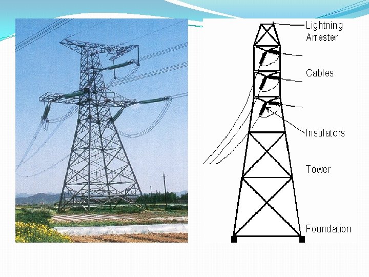
HIGH RISE STRUCTURES Transmission Tower Transmission towers are tall structures with relatively small cross section and with a large ratio between the height and the maximum. Towers are also called as masts or pylon. Tower is a single cantilever freely standing , self-supporting structures fixed at its base. Transmission towers structures that are pin – connected to its foundation and braced with guys or other elements. Similar examples are water towers, radio, television towers, radio relay system etc. , These towers of power transmission lines are used to support transmission cables carry transmitting voltages exceeding 1, 32, 000 volts
Over long distance, since these cables carry heavy voltage, they provide necessary clearance, where the transmission cables have maximum sag On general the towers may be built up with three or more legs. But generally all towers are built up with four legs and spared suitably. This is because four leg gives sufficient stability to the structures. There are different types of them: Self supporting type Flexible type Semi-flexible Line tower Angle tower Self supporting wide base Guyed type
Self – supporting type towers are generally rigid in both the transverse and longitudinal directions Flexible type towers are not rigid in the longitudinal direction ie. , in the direction along the transmission cables Line towers, when there is a straight portion of the power line, line towers are preferred Angle towers, when the direction of the power line is changed angle towers are provided The height of these towers should be within 20 – 40 m The towers of such height provide 6 – 10 m clearance from the ground surface to the point of maximum sag of the cables These towers are also known as single, double or multiple circuit towers depending upon the no of circuits supported by the towers
Single diagonal bracing tower have long free length and double diagonal bracing or cross diagonal tower Radio and television towers are self – supporting towers. For there towers rigid diaphragms are provided at the top and at several intermediate sections to the increase the stiffness of cross sections. In masts they are guyed with wire ropes at one or more levels The vertical loads acting on towers are the dead load and live load The vertical loads on the power transmission line towers include self weight of towers insulators, fittings, ice coating, line man with tools The self weight of towers is found by a general existing Ryle’s empirical formula (For suspension , dead load towers)
SKYSCRAPERS Skyscraper (high rise) is a tall habitable building. Emporis data committee defines skyscraper as a building which is 35 meters or greater in height , and is divided at regular intervals into occupiable levels. Some structural engineers define a skyscraper as any vertical construction for which wind is a more significant load factor than weight. The first skyscrapers is considered the Home Insurance Building in Chicago Ten storey structure was constructed in 1884 – 1885. Another contender for the title is the 1892 ten – storey Wainwright Building by Louis Sullivan, which still stands in St. Louis, Missouri.
The crucial developments for skyscrapers were steel, reinforced concrete, water pumps, elevators. Until the 19 th century, buildings of over six stories were rare. It was impractical to have people walk up so many flights of stairs, and water pressure could only provide running water to about 50 feet (15 m) The weight-bearing components of skyscrapers differ substantially from those of other buildings. Their walls can support buildings up to about four stories, while skyscrapers are larger buildings that must be supported by a skeletal frame The walls than hang off this frame like curtains hence the architectural term curtain wall for tall systems of glass that are laterally supported by these skeletal frames. Skyscrapers was a nautical term for a tall mast or sail on a sailing ship
Worlds 10 Tallest Buildings Rank Building, City Year Storyes Height in Meters Feet 1 Freedom Towers, New York 2005 121 541 1776 2 Taipei 101, Taipei, Taiwan 2004 101 509 1671 3 Petronas twin tower, Kuala lumpur, Malaysia 1998 88 452 1483 4 Sears tower, Chicago 1974 110 442 1451 5 Jin Mao Buildings, Shanghai 1999 88 421 1380 6 Two International Finance Centre, Hong Kong 2003 88 415 1362 7 CITIC Plaza, Guangzhou, China 1996 80 391 1283 8 Shun Hing Square, Shenzhen, China 1996 69 384 1260 9 Empire State Building, New York 1931 102 381 1250 10 Central Plaza, Hong Kong 1992 78 374 1227
COOLING TOWER Cooling towers are widely used for cooling large quantities of water in thermal power station , refineries , atomic power plants , steel plants , air conditioning and other industrial plant. A cooling towers incorporates a draft tower distributing and spraying devices and a cold water basin. A typical section of hyperbolic cooling tower of height 100 m The draft is induced naturally or mechanically. Hot water is pumped to a certain height and then distributed through a piping system of nozzles, where it splashes over a system called “Filling or Stacking” The filling may be of wood or transite material placed in several layers
The water splashes drips and flows through the layer of filling The air which is forced upward either mechanically or by atmospheric pressure difference rises through the driplets or films of the hot water and consequently cools the water through evaporation and convection The cooled water is collected in a pond at the bottom of the towers and then recirculated for industrial use Hyperboloid of revolution The hyperboloid of revolution of one sheet is generally used for cooling towers of thermal station The great advantage of this type of shell is that it is generated by two families of intersecting straight lines and the form work can be achieved by straight boards warped only slightly over the lengths The intersecting grid of straight lines forms rhombuses of intersection
The shell surface can also be built of pre-cast rhombic elements which are repeated along the complete circumferences at fixed heights The generation of the hyperboloid of revolution is by intersecting straight lines
MATERIAL HANDLING Material handling is the movement, storage, control & protection of materials, goods & products throughout the process of manufacturing, distribution consumption and disposal. The focus is on the methods, mechanical equipment systems and related controls used to achieve these functions Material handling management consists use of a proper technique for moving, transporting, storing or distributing materials with or without the help of mechanical appliances. Because of various complexities in the construction process, management must be fully acquainted with various material handling devices so that unit cost of construction can be down
All material handling activities must be simplified and must be fully safe preventing any accidents Also material movement planning must be economical is terms of time and labour Material handling objective: �The right amount �The right material �At the right time �In the right position �In the right sequence �For the right cost
Ø The handling of material depends on three items. They identified as follows �Identification of source of building material �Identification of quantity and quality of material �Identification of cost of building material Principles Orientation principle Planning principle System principle Unit load principle Space utilization principle
Standardization principle Safety principle Ergonomic principle Computerization principle Energy principle System flow principle Ecology principle Layout principle Mechanization principle Cost principle Flexibility principle Maintenance principle Simplification principle Obsolescence principle Gravity principle
MATERIAL MANAGEMENT Material management is concerned with ensuring that the quantity and quality required are on the job as per requirement The construction manager is concerned about the nature of material handling problems like quantity , quality , price , delivery date , mode of transportation , inspection , counting , cost , storage and protection. Considerable time and effort is spent on a practical network that will satisfy and resource limitations However, such a schedule is not used unless supported by the timely delivery of materials
The material for delivery to the site can be broadly classified as follows, Bulk items Standard items Fabricated items Bulk items - like earth , bricks , cement , sand , stone chips , steel sheet and asphalt that are obtained in a semi-processed state Standard items - all shelf items that can be procured from the market like pipes and pipe fittings. Fabricated items – are the items that are specially built as per specification and sizes for the project. Built as per specification like roof truss, doors, windows, electrical panel etc.
ERECTING LIGHT WEIGHT COMPONENTS ON TALL STRUCTURE Tall buildings are generally multi storey structures where greater part of construction of beams and stanchreons Erection Procedure for Multi Storey Building The order of erection follows pattern of columns, girder and beams or columns, trusses and purlins. Buildings are generally erected by cranes and beyond the reach are erected guy derricks The step wise operation is as follows Guy derrick mast is assembled on ground with its base in approximate required location. The mast is tipped up vertically and guys are anchored to column bases. The boom is inserted and topping lift and load lines are served. The derrick is ready to operate. The first – tier steel is erected
The bottom is removed from boom seat by picking with topping lift falls, revolved 18 degree and placed in a temporary jumping shoe. The top of boom is guyed off with temporary guys The load falls are attached to mast above its center of gravity, the mast guys are moved to top of next tier and mast is raised to its new position. The mast guys are adjusted and load falls unhooked The temporary guys of boom are removed and the topping lift falls are used to raise the boom and place it in the boom seat. The derrick is now ready to operate and the next tier of steel is erected This operation is repeated until all tiers are erected
Safety Rules See that the equipment is not over loaded. Be certain of load to be lifted All bolts and splice material on lattice derricks and crane sections have been inserted Do not open the legs of brother chains to too large an angle The rings of chain slings is trig enough for crane hook Avoid sudden shocks when lifting
SUPPORT STRUCTURE FOR HEAVY EQUIPMENT Column Base Foundation is necessary for a column to distribute the column load on sufficient area of the soil so that the bearing capacity of the soil is not exceeded, it is also equally important that the column load be applied on sufficient area of the concrete foundation so that bearing strength of the concrete is not exceeded A steel base plate is therefore used to spread the column loaf on sufficient area of the concrete foundation Base plate used may be of following types Slab bases Gusseted bases
Slab bases : In this case the column stands directly on the base plate the bearing end of the column is machined so that the column load is transferred to the slab base by bearing Gusseted base: Gusseted base plates are used in columns carrying heavy loads. In this case fastenings are used to connect the base plate and the column in the form of gusset plate, angles etc. , In case the end of the column is sufficiently machined so as to provide full bearing on the base plate, it is usual to assume that half the column load is liable to be transferred to the base plate through the fastenings and the balance load is transferred to the base plate by direct bearing. Suppose the ends of the column and gusset plates are not exactly faced for full or complete bearing. Then it is usual to design the fastenings to transmit all the forces to which the base is subjected.
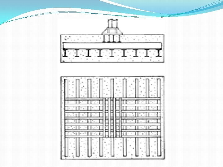
Grillage foundation: It is provided for a column carrying heavy load when it has to transfer its load to a soil of low bearing strength This foundation consists of two or more layers or tiers of steel beams, the layers being provide one above the other at right angles at each other. The beams are completely encased in well compared concrete. Generally only two tiers of beams are used The column rests on a base plate through which the load is transmitted to the upper tiers beams These beams in turn transfer the loads to the lower tier beams. From the lower tier beams the load will be transmitted to the soil.
ERECTION OF ARTICULATE STRUCTURE Bow String Girder Type Bridges The bow string girder type bridges derives its name from its shape. The arch rib and the tie respectively resemble bow and string. The flooring of bridge rests on ties and the load is transmitted to the arch rib through suspenders Suitable bracing may also be provided in case of steel bow string girders The bow string girder type bridge removes the following two disadvantages of the arch bridges The horizontal thrust is resisted by ties, hence the reactions at supports are vertical and not inclined as in case of the arch bridges. As a result of vertical reactions the supports require lighter sections
The bow – string girders project above the formation level of road or railway line. Hence, the question of accommodating the rise between the level of approaches and the springing level of arch close not arise The bow string girder type bridges are therefore very much suitable for multiple spans and at places where the available clearance is restricted Deck Type and Through Types Truss Bridges In the deck type truss bridges, the floor system rests on the top chord. In the through type truss bridges, the floor system rests on the bottom chord. Through type warren truss bridge with verticals Although the parallel chord trusses are used for the through type truss bridges, but the lines of various numbers of parallel chord truss bridges are more in harmony with deck type truss bridges
Component Parts of Truss Bridge The various component parts consists of The main vertical trusses The floor system The bottom lateral bracing The top lateral bracing The portal bracing The sway bracing
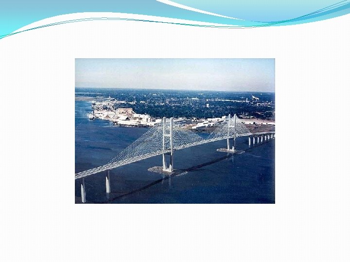
Cable Stayed Bridge Cable – stayed bridges may look similar to suspensions bridges both have roadways that hang from cables and both have towers But the two bridges support the load of the roadway in very different ways. The difference lies in how the cables are connected to the towers In suspension bridges, the cables ride freely across the towers, transmitting the load to the anchorages at either end In cable-stayed bridges, the cables are attached to the towers, which alone bear the load The cables can be attached to the roadway in a variety of ways. In radial pattern, cables extend from several points on the road to a single point at the top of the tower In a parallel pattern, cables are attached at different heights along the tower, running parallel to one other
Construction Sequence of Cable Stayed Bridge The cable stayed bridges are similar to the suspension bridge except that there are no suspenders in the cable stayed bridges and the cables are directly stretched from towers to connect with the decking Thus no special internal anchorage is required for the cables as in case of suspension bridges because the anchorage at one end is done in the girder and at the other on top of tower Each because in the girder introduces horizontal and vertical forces The cables can be arranged with two plane system or one plane system. The two plane system requires additional width to accommodate the towers and deck anchorages But in case of one plane system the anchorage at deck level can be accommodated in the traffic median and it results in the least value of total width of the deck
In principle the cable stayed bridge essentially of the following three elements Bridge deck Pylons or tower Stay cables The stay cables are the principal structural elements because they play an important role in the design, stability and performance of the structure as a whole The different types of stay cables are locked coil wire ropes or stranded ropes long lay spiral strand cables parallel or semi parallel wire cables
The deck in case of the cable – stayed bridges is supported by a number of cables meeting in a bunch at the tower, known as the harp form The use of multiple cables facilities smaller distances between points of supports for the deck girders and it results in the reduced structural depth The cable stayed decks are less prone to the wind induced oscillations than the suspension bridges because of the damping effect of the inclined cables The brick deck may be in the form of steel prone or RCC or prestressed concrete girders. The concrete girders possess the following advantages As their damping effect is very high, the vibration effects are also small They possess much higher stiffness and hence, they exhibit comparatively less deflection