UNIT ISUB STRUCTURE CONSTRUCTION 1 Box Jacking Need

UNIT I-SUB STRUCTURE CONSTRUCTION 1. Box Jacking: Need – elements – concept – precautions – advantages. 2. Pipe jacking: Technique – factors – applications – advantages. 3. Diaphragm walls – methods – sheet piles – applications – advantages. 4. Piling techniques: Classifications – factors. 5. Well and caisson: Types – sinking method – precautions. 6. Coffer dam: Purpose – types – techniques. 7. Cable anchoring – screw anchor – necessity- applications. 8. Grouting: Need – materials – techniques – applications – guniting and shotcreting. 9. Well points - dewatering – techniques.

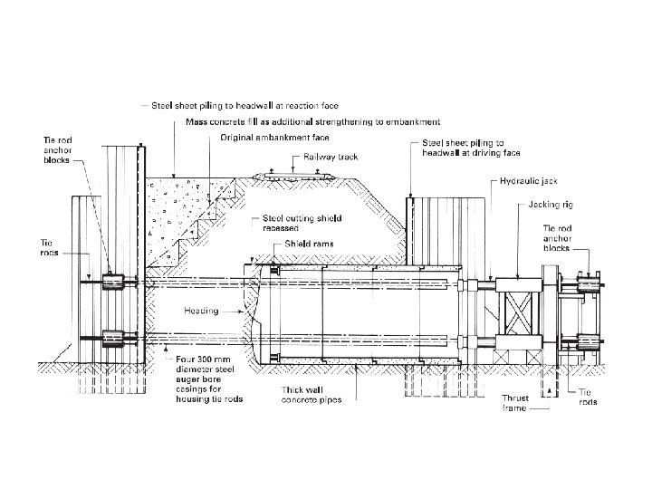
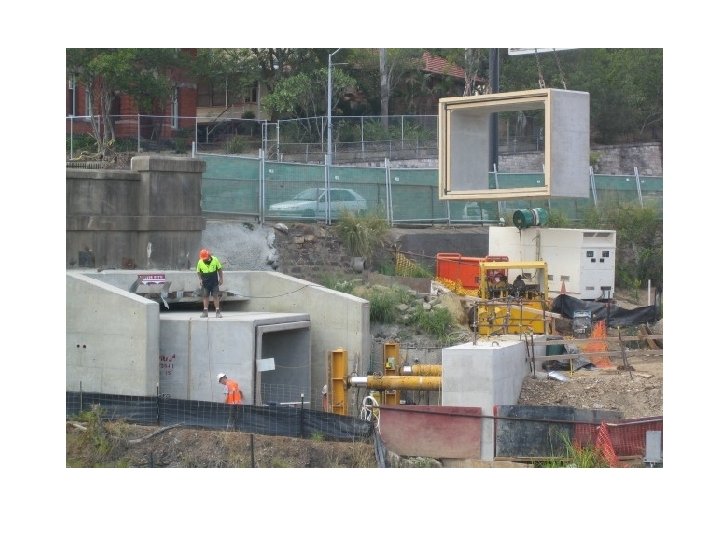
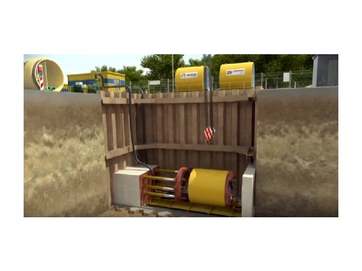
1. Box Jacking: Need – elements – concept – precautions – advantages. PRECAST CONCRETE BOX • It is the process in which a pre-cast R. C. C box or a rigid box is pushed into the soil with the help of hydraulic jacks. It is non-intrusive method beneath the existing surface. It is more often used when a subway or a aqueduct or a underground structure is to be constructed. • These include subways, stream crossings, animal (badger) crossings, sewers and sea outfalls. They are not limited to horizontal use, and may also be used as vertical access shafts. • First the box section is designed and cast at the site or can be transported to the site according to the requirement. The foundation boxes are jacked into the ground designed to carry the dead and the live loads. • Then the high capacity jacks are placed at the back and it pushes the box into the ground. All purpose designed tunneling shield is provided in the front end. Then the box is jacked carefully through the earth. Excavation and jacking are done in small increments in advance.

Shielding ram made of steel

Box culvert and hydraulic jacking set

Key segments/Elements 1. Sheet pile 2. Thrust frame 3. Thrust bed 4. Shear key 5. Hydraulic jack 6. Jacking rig 7. Steel cutting shield ram 8. Thin wall concrete pipes Thin wall high strength pipes Smooth outer surface to avoid friction Laser guided Need Sustainable Economical Ecological Trenchless installation Reduce pollution Avoiding traffic disturbance Speedy construction

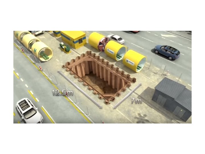
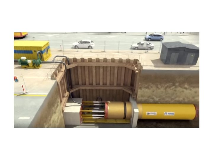
Setting up stage – launching pit/ header and receiving pit

Shield ram
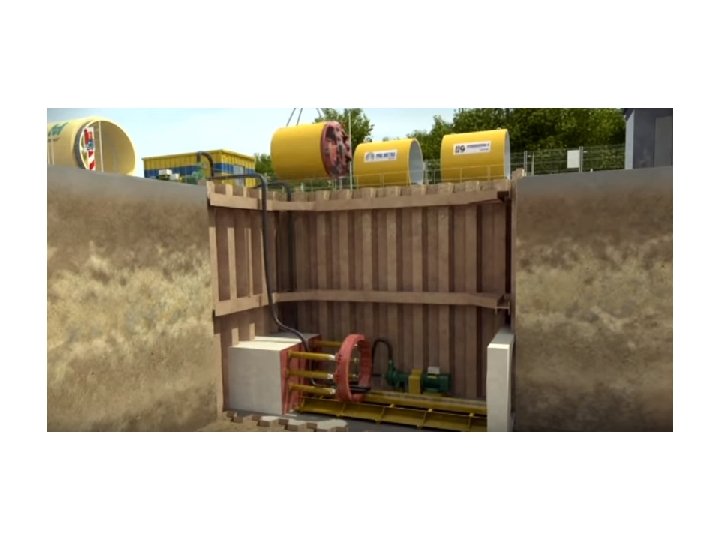

2. Pipe jacking: Technique – factors – applications – advantages. PIPE JACKING This method can be used for the installation of pipes from 150 to 3, 600 mm diameter but is mainly employed on the larger diameters of over 1. 000 m. Basically the procedure is to force the pipes into the subsoil by means of a series of hydraulic jacks, and excavate, as the driving proceeds, from within the pipes by hand or machine according to site conditions. The leading pipe is usually fitted with a steel shield or hood to aid the driving process. This is a very safe method, because the excavation work is carried out from within the casing or liner and the danger of collapsing excavations is eliminated; There is also no disruption of the surface or underground services, and it is a practical method for most types of subsoil.

The most common method is to work from a jacking or working pit, which is formed in a similar manner to traditional shafts except that a framed thrust pad is needed from which to operate the hydraulic jacks. The working pit must be large enough for the jacks to be extended and to allow for new pipe sections to be lowered into the working bay at the bottom.
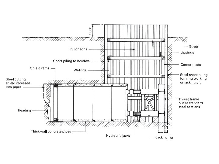

Two materials are in common use for the pipes: concrete and steel. Spun concrete pipes are specially designed with thick walls, and have a rubber joint, making them especially suitable for sewers without the need for extra strengthening. Larger-diameter pipes for pedestrian subway constructions are usually made of cast concrete and can have special bolted connections making the joints watertight, which also renders them suitable for use as sewer pipes. Steel pipes have a wall thickness relative to their diameter, and usually have welded joints to give high tensile strength, the alternative being a flanged and bolted joint. They are obtainable with various coatings and linings to meet special requirements such as corrosive-bearing effluents.

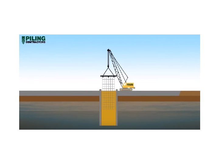
Diaphragm walls – methods – sheet piles – applications – advantages. DIAPHRAGM WALLS A diaphragm can be defined as a dividing membrane, and in the context of building a diaphragm wall can be used as a retaining wall to form the perimeter wall of a basement structure, to act as a cut-off wall for river or similar embankments, and to retain large masses of soil such as a side wall of a road underpass. In-situ concrete diaphragm walls are being used to a large extent in modern construction work and can give the following advantages: 1. The final wall can be designed and constructed as the required structural wall. 2. Diaphragm walls can be constructed before the bulk excavation takes place, thus eliminating the need for temporary works such as timbering. 3. Methods that can be employed to construct the wall are relatively quiet and have little or no vibration. 4. Work can be carried out immediately adjacent to an existing structure.

5. 6. 7. 8. 9. They may be designed to resist vertical and/or horizontal forces. Walls are watertight when constructed. Virtually any plan shape is possible. Overall they are an economic method for the construction of basement or retaining walls. There are two methods by which a cast in-situ diaphragm wall may be constructed: touching or interlocking bored piles; excavation of a trench using the bentonite slurry method.

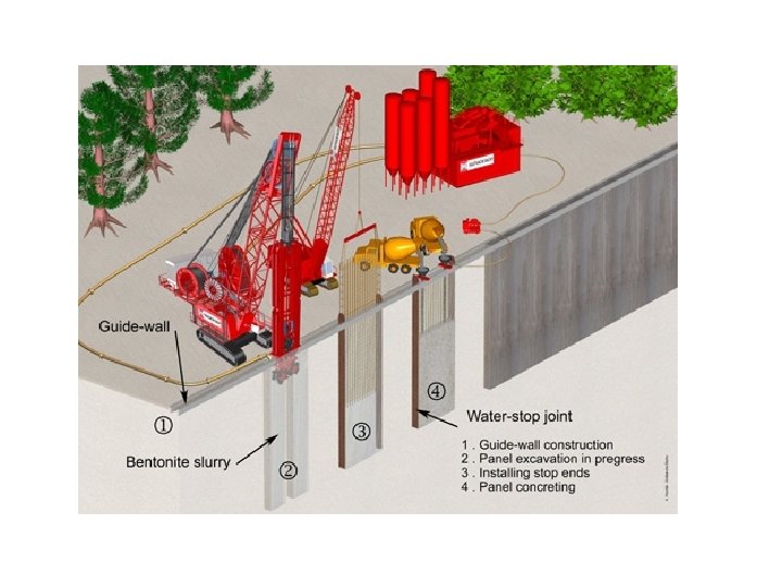
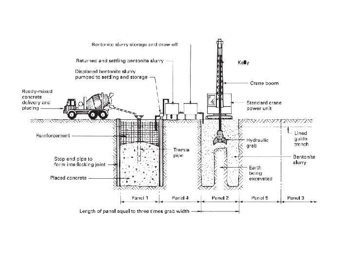
The general method used to construct diaphragm walls is the bentonite slurry system. When mixed with the correct amount of water bentonite shows thixotropic properties, giving a liquid behaviour when agitated and a gel structure when undisturbed. The basic procedure is to replace the excavated soil with the bentonite slurry as the work proceeds. The slurry forms a soft gel or ‘filter cake’ at the interface of the excavation sides with slight penetration into the subsoil. Hydrostatic pressure caused by the bentonite slurry thrusting on the filter cake cushion is sufficient to hold back the subsoil and any groundwater that may be present and can be successfully employed up to 36. 000 m deep.

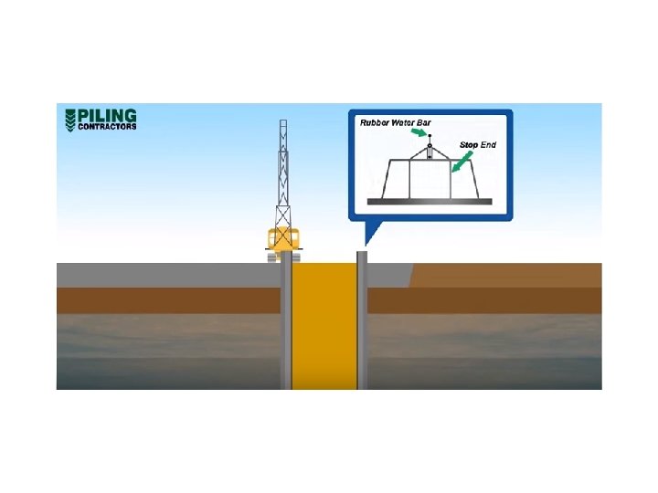
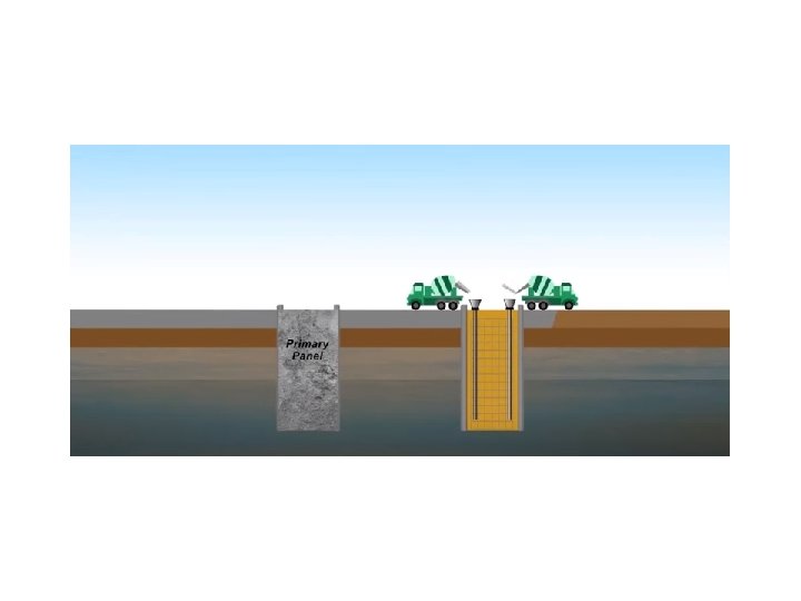
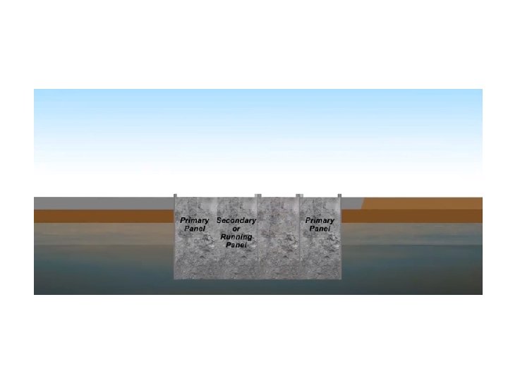
Diaphragm walls constructed by this method are executed in alternate panels from 4. 500 m to 7. 000 m long with widths ranging from 500 to 900 mm using a specially designed hydraulic grab attached to a standard crane, or by using a continuous cutting and recirculating machine. Before the general excavation commences, a guide trench about 1. 000 m deep is excavated and lined with lightly reinforced walls. These walls act as a guide line for the excavating machinery and provide a reservoir for the slurry, enabling pavings and underground services to be broken out ahead of the excavation.

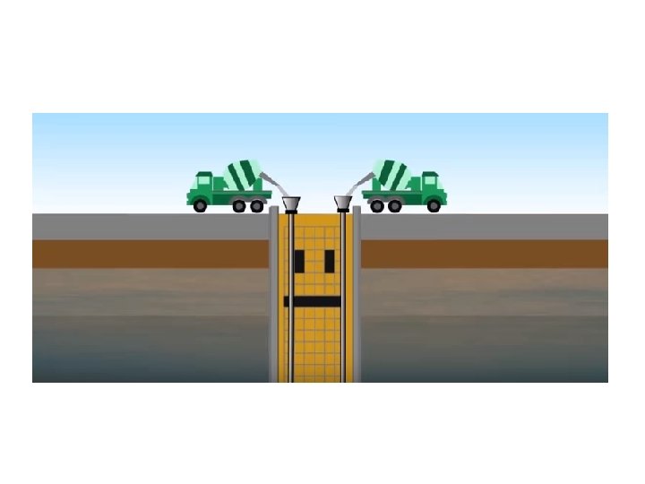
To form an interlocking and watertight joint at each end of the panel, circular stop end pipes are placed in the bentonite-filled excavation before the concrete is placed. The continuous operation of concreting the panel is carried out using a tremie pipe and a concrete mix designed to have good flow properties without the tendency to segregate. This will require a concrete with a high slump of about 200 mm but with highstrength properties ranging from 20 to 40 N/mm 2. Generally the rate of pour is in the region of 15 to 20 m 3 per hour, and as the concrete is introduced into the excavated panel it will displace the bentonite slurry, which is less dense than the concrete, which can be stored for reuse or transferred to the next panel being excavated. The ideal situation is to have the two operations acting simultaneously and in complete unison.

Before the concrete is placed, reinforcement cages of high yield or mild steel bars are fabricated on site in one or two lengths. Single length cages of up to 20. 000 m are possible; where cages in excess of this are required they are usually spot-welded together when the first cage is projecting about 1. 000 m above the slurry level. The usual recommended minimum cover is 100 mm, which is maintained by having spacing blocks or rings attached to the outer bars of the cage. Upon completion of the concreting the bentonite slurry must be removed from the site either by tanker or by diluting so that it can be discharged into the surface water sewers by agreement with the local authority.

Key segments Guide wall Bentonite slurry Rubber water bar stop end Steel cage High strength concrete Narrow trench excavated in ground supported by an engineered fluid used in congested areas or where the excavation depth is very deep well suited for deep basements, underground rail stations, tunnel approaches and such like.

Secant pile walls (hard / soft, hard / firm or hard / hard, cast in situ bored or CFA). A guide wall is required for this method of construction to ensure that piles are accurately located to achieve an interlock (or secant) cut into the adjacent pile. A secant pile wall uses interlocking male and female cast in situ piles to produce a retaining structure. Construction is carried out sequentially with primary (female) piles installed first then secondary (male) piles cut into the primary piles forming a continuous wall.
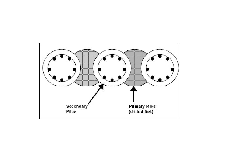

This wall type provides some degree of water retention but is not watertight. The primary pile may also be reinforced. The construction sequence becomes particularly critical when needing to cut segments of 40 MPa concrete piles to allow installation of the secondary pile. High torque drill rigs and specially designed cutting tools are required. At exposed heights greater than 9 – 12 m it often becomes uneconomic to achieve continuous pile overlap and hence a diaphragm wall generally is more suitable.

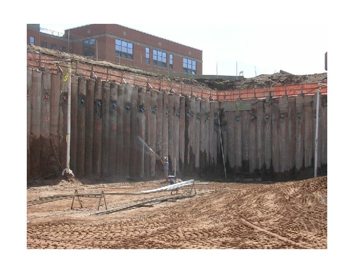
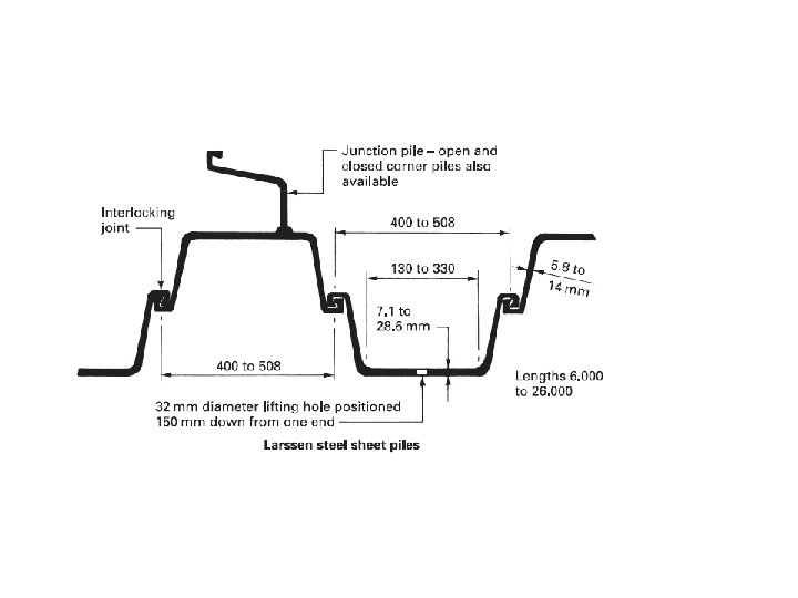
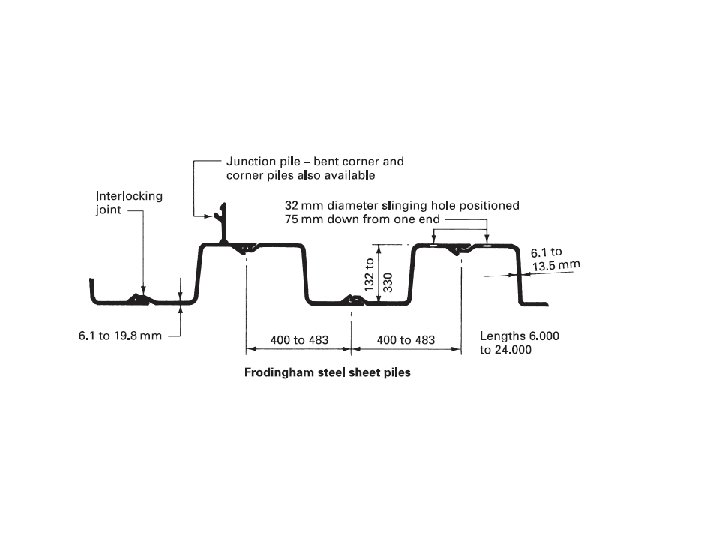
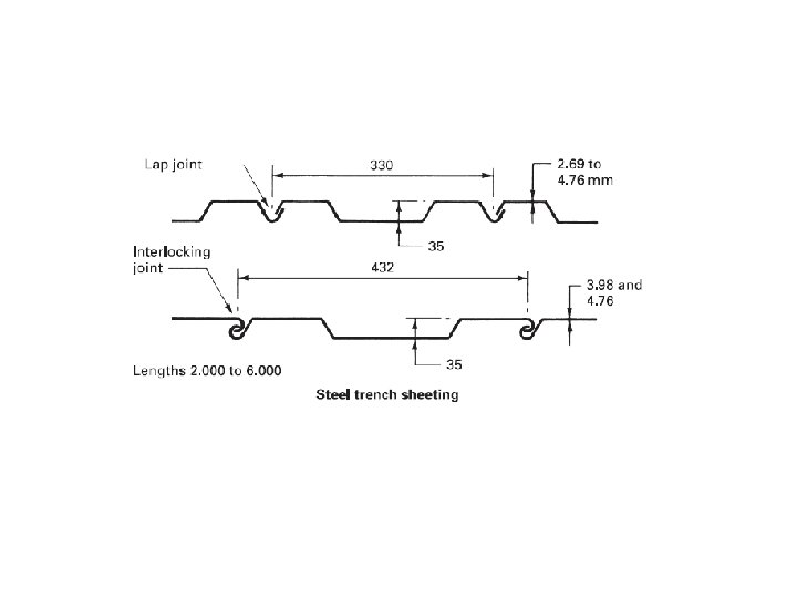
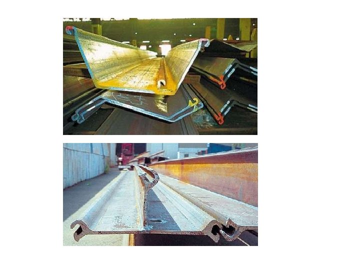
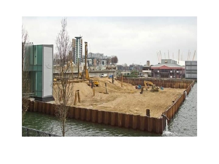
STEEL SHEET PILING Steel sheet piling is the most common form of sheet piling; it can be used in temporary works such as excavations in soft and/or waterlogged soils and in the construction of cofferdams. This material can also be used to form permanent retaining walls, especially those used for river bank strengthening, and in the construction of jetties. Three common forms of steel sheet pile are the Larssen, Frodingham and straight-web piles, all of which have an interlocking joint to form a water seal, which may need fill gaps where high water pressures are encountered. Straight-web sheet piles are used to form cellular cofferdams. Larssen and Frodingham sheet piles are suitable for all uses except for the cellular cofferdam, and can be obtained in lengths up to 18. 000 m according to the particular section.

When sheet piles are being driven there is a tendency for them to creep or lean in the direction of driving. Correct driving methods will help to eliminate this tendency, and the generally accepted method is to install the piles in panels.

• Sheet pile wall advantages are: • Sheet pile wall disadvantages are: 1. Provides high resistance to driving stresses. 1. Sections can rarely be used as part of the permanent structure. 2. Light weight 2. 3. Can be reused on several projects. 4. Long service life above or below water with modest protection. Installation of sheet piles is difficult in soils with boulders or cobbles. In such cases, the desired wall depths may not be reached. 3. Excavation shapes are dictated by the sheet pile section and interlocking elements. 4. Sheet pile driving may cause neighborhood disturbance. 5. Settlements in adjacent properties may take place due to installation vibrations. 5. 6. Easy to adapt the pile length by either welding or bolting Can produce a watertight wall

APPLICATIONS OF SHEET PILE WALLS • As stated earlier, one of the effective methods to retain a soil mass is to install a vertical wall which consists of long thin element such as steel, concrete or wood that are driven in the ground. The elements are usually connected by interlocking joints.
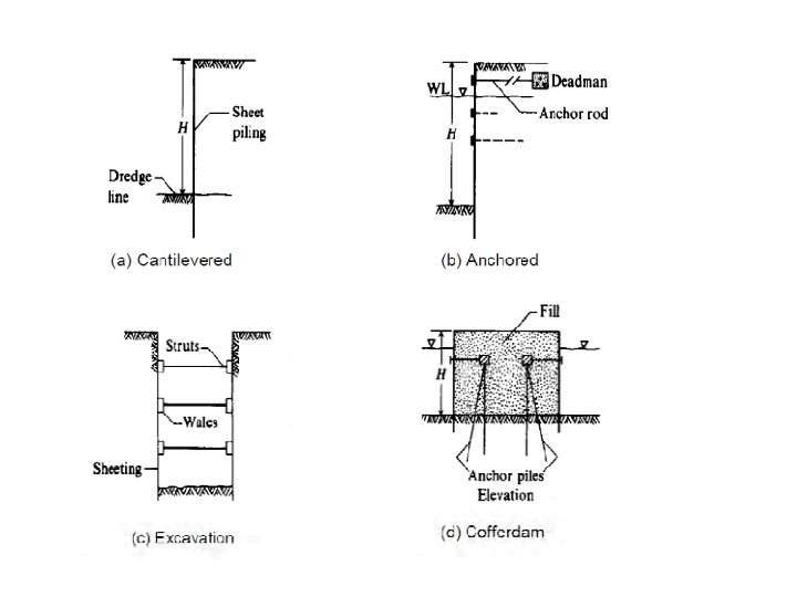

Cantilever sheet pile walls 6 m or less than • Cantilevered sheet piles are usually used for the height of about dredge line. (Fig. 1 -a) • In geotechnical practices, cantilever embedded retaining structures are specifically used for protecting permanent and temporary excavations, for highway constructions, and protection of landslides. These stuctures are mostly sheet walls as temporary retaining structures, and pile walls and diaphragms as permanent retaining structures.

Anchored sheet piles • Anchored sheet piles • When the height of sheet pile is more than 6 m, it is economical to use sheet pile which is anchored near its top. (Fig. 1 -b) Anchoring the sheet pile cause less penetration depth and also less moment to the sheet pile. • Well constructed anchor walls undergo less lateral deflection than braced walls and so provide a better control of back-slope subsidence. Anchor installation only requires a small excavation to allow equipment access. • The anchor will maintain their load through the excavation sequence.

• • Excavation The sections can either be cantilevered to support the excavation, depending on the imposed loads, or they can be restrained by a specially designed mechanism with anchor. • During excavation ground anchors are progressively installed to restrain the sheet piling. This creates a ‘reinforced earth zone’ behind the sheet piling to form a retaining wall structure around the excavation. Hence, deep excavation can be supported in a wide range of ground conditions. • • Cofferdams A cofferdam is a temporary structure designed to keep water and soil out of the excavation in which a bridge pier or other structure is built. (Fig. 1 -d) • When construction must take place below the water level, a cofferdam is built to give dry work enviroment. Sheet piling is driven around the work site, seal concrete is placed into the bottom to prevent water from seeping in from underneath the sheet piling.

COFFER DAM

A cofferdam may be defined as a temporary box structure constructed in earth or water to exclude soil and/or water from a construction area. A cofferdam is a temporary structure designed to keep water and/or soil out of the excavation in which a bridge pier or other structure is built. It is usually formed to enable the formation of foundations to be carried out in safe working conditions. It is common practice to use interlocking steel trench sheeting or steel sheet piling to form the cofferdam, but any material that will fulfil the same function can be used, including timber piles, precast concrete piles, earth-filled crib walls and banks of soil and rock. It must be clearly understood that, to be safe, economic and effective, cofferdams must be the subject of structural design. Cofferdams constructed from steel sheet piles or steel trench sheeting can be considered under two headings: • single-skin cofferdams; • double-skin cofferdams.

PURPOSE TO USE COFFER DAM STRUCTURE • To retain Soil & Water • Can be used as either Temporary or Permanent • Main purpose is to provide dry working area for workers • It is constructed to facilitate pile driving operations. • It is used to place grillage as well as the raft foundations • It is used , when the foundations for piers and abutments of a bridge, dams, locks, etc. are to be constructed. • Some times it is also provided to store water temporarily.

Cofferdams can be used in all the sectors as explained below. Civil Engineering: Underground Car Parking, Foundation, Basement Construction Transport Engineering: Bridge Pier, Support Walls, Ramps, Ground Water Retention, Tunnel Work etc. Water Engineering: Weirs, Culverts, Flood Protection Walls, Scour Protection Walls, Securing Embankment etc. Port Construction: Dock Works, Jetty Works etc.

Types of Coffer Dam 1. Earth fill cofferdams - mainly for low level water 2. Sand Bag Coffer Dam – to divert coarse of water 3. Rock fill cofferdams 4. Braced / Sheet Pile Coffer Dam- Consisting of Sheet Piles, mainly used in shallow water depth (i) Single wall coffer dams (ii) Double wall coffer dams (iii) Cellular cofferdams

Earth cofferdam These are the simplest type of cofferdams well-adapted to depths of water upto 3 m. Earth embankments are constructed around the area to be dewatered. The earth coffer dams are built of local soils, preferably fine sand. These usually have a clay core or a vertically driven sheet piling in the middle. The upstream slope of the bank is covered with a rip rap. A successful coffer dam need not be completely watertight. For reason of economy, it is not possible to make it watertight and hence some seepage of water into the excavation is usually tolerated. The water collected is pumped out of the excavation. The embankment should be provided with a minimum free board of 1 m to prevent overtopping by waves. Sand-bag coffer dams are used in an emergency.

Rockfill cofferdam Rockfill coffer dams made of rockfill are sometimes used to enclose the site to be dewatered. These are permeable and are usually provided with an impervious membrane of soil to reduce seepage. The crest and the upper part of the impervious membrane are provided with rip rap to provide protection against wave action. Overtopping doesn’t cause serious damage in case of rockfill coffer dams. The slopes of a rockfill cofferdam can be made as steep as 1 horizontal to 1. 5 vertical.

Single sheet pile cofferdam These are generally used to enclose small foundation sites in water for bridges at a relatively shallow depth. In this type of coffer dams, there is a single row of cantilever sheet piles. The piles are sometimes heavily braced. Joints in the steet piles are properly sealed. This type of coffer dams are suitable for moderateflow velocities of water and for depth upto 4 m. The depth of penetration below ground surface is about 0. 25 h for coarse sand gravels, 0. 5 h for dine sand 0. 85 h for silts, where h is the depth of water. Sometimes single-sheet coffer dams are provided with earth fills on one or both sides to increase the lateral stability. The figure of single sheet pile cofferdam is shown on the right.

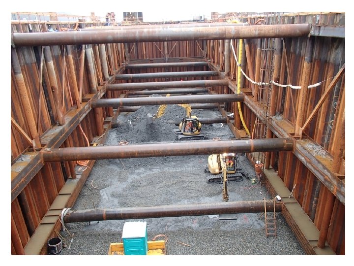
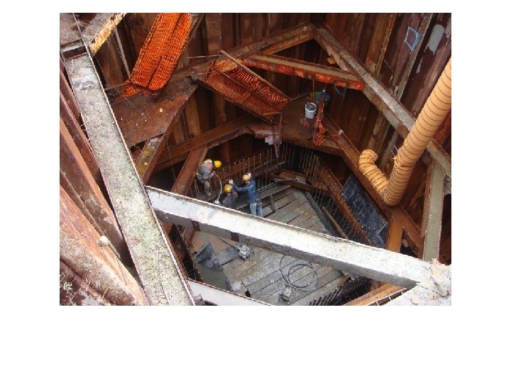
Braced cofferdam A braced coffer dam is formed by driving two rows of vertical sheeting and bracing with wale and struts. These are similar to sheeting and bracing system with one basic difference that braced cuts are required for excavations in dry areas whereas braced coffer damsare used to isolate a working area surrounded by water. The braced coffer dams are susceptible to flood damage. Braced cofferdams are sometimes used as land coffer dams to prevent ground from entering the foundation pile pit on land to support the soil so as to prevent cave in. After the pit is dewatered, the structure is concreted. When concreting has been completed above the water level, the coffer dam is removed.

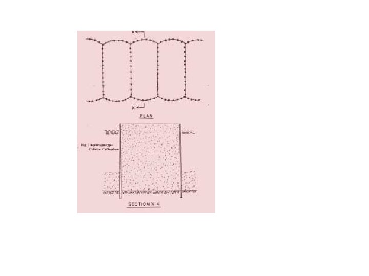
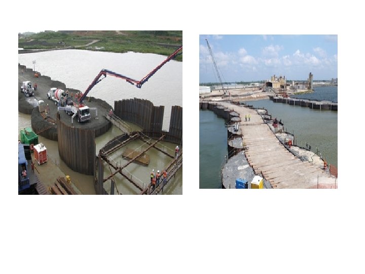
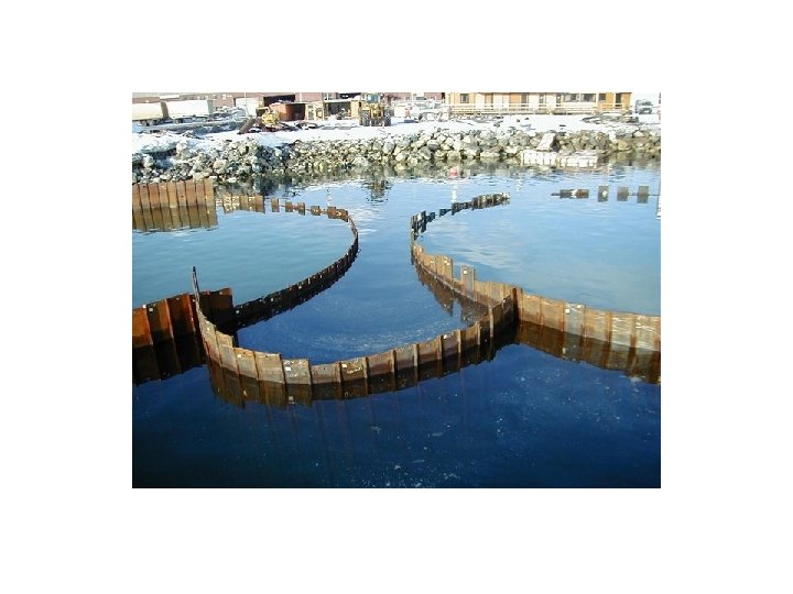
Cellular cofferdam This is constructed by driving sheet piles of special shapes to form a series of cells. Te cells are interconnected to form a watertight wall. These cells are filled with soil to provide stabilizing force against lateral pressure. Basically, there are two types of cellular coffer dams that are commonly used: Diaphragm Type: This type of cellular cofferdam consists of circular arcs on the inner and outer sides which are connected by straight diaphragm walls. The connection between the curved parts and the diaphragms are made by means of a specially fabricated element. The coffer dam is thus made from inter-connected steel sheet piles. The cells are filled with coarse-grained soils which increase the weight of the cofferdam and its stability. The leakage through the coffer dam is also reduced.

Circular Type: It consists of a set of large diameter main circular cells interconnected by arcs of smaller cells. The walls of the connecting cells are perpendicular to the walls of the main circular cells of large diameter. The segmental arcs are joined by special T-piles to the main cells. The circular type cellular cofferdams are selfsustaining, and therefore independent of the adjacent circular cells. Each cell can be filled independently. The stability of such cells is much greater as compared with that of the diaphragm type. However, the circular cells are more expensive than the diaphragm type, as these require more sheet piles and greater skill in setting and driving the piles. Because the diameter of circular cells is limited by interlock tension, their ability to resist lateral pressure due to high heads is limited.

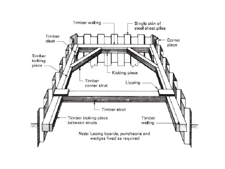
SINGLE-SKIN COFFERDAMS These consist of a suitably supported single enclosing row of sheeting or sheet piles forming an almost completely watertight box. Trench sheeting could be considered for light loadings up to an excavation depth of 3. 000 m below the existing soil or water level, whereas sheet piles are usually suitable for excavation depths of up to 15. 000 m. The small amount of seepage that will occur through the interlocking joints must not be in excess of that which can be comfortably controlled by a pump; alternatively the joints can be sealed by filling with suitable mastics, bitumastic compounds or silicone sealants.

Single-skin cofferdams constructed to act as cantilevers are possible in all soils and most cofferdams are therefore either braced and strutted or anchored using tie rods or ground anchors. Standard structural steel sections can be used to form the support system. Typical cofferdam support arrangements are shown in Figs. Single-skin cofferdams that are circular in plan can also be constructed using ring beams of concrete or steel to act as bracing without the need for strutting. Diameters up to 36. 000 m are economically possible using this method.

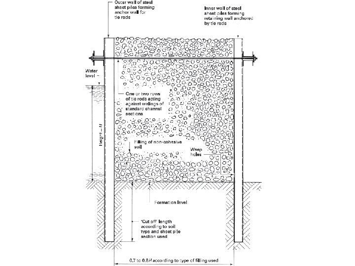
DOUBLE-SKIN COFFERDAMS These are self-supporting gravity structures constructed by using two parallel rows of piles with a filling material placed in the void created. Gravity-type cofferdams can also be formed by using straight-web sheet pile sections arranged as a cellular construction (see Figs). The stability of these forms of cofferdam depends upon the design and arrangement of the sheet piling and upon the nature of the filling material.

Piling techniques: Classifications – factors. A pile can be defined as a column inserted in the ground to transmit the structural loads to a lower level of subsoil. The pile foundations needed when: 1. low bearing capacity of the subsoil; 2. heavy point loads of the structure exceeding the soil bearing capacity; 3. presence of highly compressible soils near the surface 4. subsoils such as clay, which may be capable of moisture movement or plastic failure; 5. high water table.

CLASSIFICATION Piled foundations may be classified by the way in which they transmit their loads to the subsoils or by the way they are formed. Transmittance of loading to a lower level may be by: End bearing The piles act as columns, carrying the loads through the overlying weak subsoils to firm strata into which the pile toe has penetrated. This can be a rock stratum or a layer of firm sand or gravel that has been compacted by the displacement and vibration encountered during the driving. Friction If a suitable load bearing stratum cannot be found at an acceptable level, particularly in stiff clay soils, The friction or floating pile is supported mainly by the adhesion or friction action of the soil around the perimeter of the pile shaft. Piles may be preformed and driven, thus displacing the soil through which they pass, and are therefore classified as displacement piles. Alternatively the soil can be bored out and subsequently replaced by a pile shaft, and such piles are classified as replacement piles.

DISPLACEMENT PILES This is a general term applied to piles that are driven, thus displacing the soil, and includes those piles that are preformed, partially preformed or are driven in-situ piles. TIMBER PILES These are usually of square sawn hardwood or softwood in lengths up to 12. 000 m with section sizes ranging from 225 mm × 225 mm to 600 mm × 600 mm. They are easy to handle, and can be driven by percussion with the minimum of experience. Most timber piles are fitted with an iron or steel driving shoe, and have an iron ring around the head to prevent splitting due to impact. Although not particularly common, they are used in sea defences such as groynes and sometimes as guide piles for large trestles in conjunction with steel sheet piling. Load bearing capacities can be up to 350 k. N per pile, depending upon section size and/or species.

PRECAST CONCRETE PILES These are used on medium to large contracts where soft soils overlying a firm stratum are encountered and at least 100 piles will be required. Lengths up to 18. 000 m with section sizes ranging from 250 mm × 250 mm to 450 mm × 450 mm carrying loadings of up to 1, 000 k. N are generally economical for the conditions mentioned above. The precast concrete driven pile has little frictional bearing strength because the driving operation moulds the cohesive soils around the shaft, which reduces the positive frictional resistance. These are used mainly in conjunction with marine structures and where overlying soils are very weak. These piles are relatively light and therefore are easy to handle and drive. Splicing can be carried out by site welding to form piles up to 15. 000 m long with load bearing capacities up to 600 k. N. Consideration must always be given to the need to apply a protective coating to the pile to guard against corrosion.

COMPOSITE PILES These are sometimes referred to as partially preformed piles, and are formed by a method that combines the use of precast and in-situ concrete or steel and in-situ concrete.

DRIVEN IN-SITU OR CAST-IN-PLACE PILES These are an alternative to preformed displacement piles and are usually applied on medium to large contracts where subsoil conditions or loadings are likely to create variations in the lengths of pile required. They can be formed economically in diameters of 300 to 600 mm with lengths up to 18. 000 m designed to carry loads of up to 1, 300 k. N. They generally require heavy piling rigs, and an open, level site where noise is unrestricted.

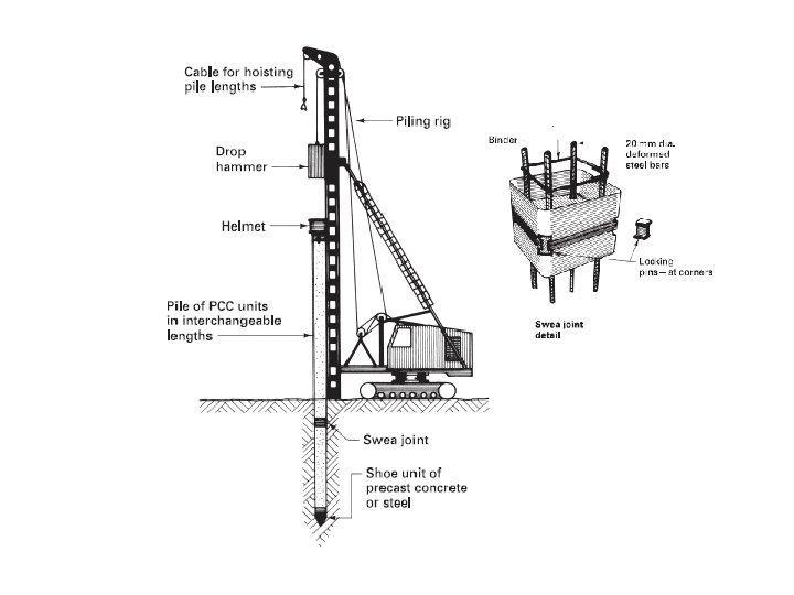
PILEDRIVING Displacement piles are generally driven into the ground by holding them in the correct position against the piling frame and applying hammer blows to the head of the pile. Exceptions are encountered, such as the cased pile shown in Fig. The piling frame can be purpose made or an adaptation of a standard crane power unit. The basic components of any piling frame are the vertical member that houses the leaders or guides, which in turn support the pile and guide the hammer onto the head of the pile. Pile hammers come in a variety of types and sizes powered by gravity, steam, compressed air or diesel. Drop hammers These are blocks of cast iron or steel with a mass range of 1, 500 to 8, 000 kg and are raised by a cable attached to a winch. The hammer, which is sometimes called a ram, is allowed to fall freely by gravity onto the pile head. The free-fall distance is controllable, but generally a distance of about 1. 200 m is employed. Drop hammers are slower than the following power hammers and may inflict more damage to the pile caps.

Single-acting hammers Activated by steam or compressed air, these have much the same effect as drop hammers in that the hammer falls freely by gravity through a distance of about 1. 500 m. Two types are available: in one case the hammer is lifted by a piston rod; in the other the piston is static and the cylinder is raised and allowed to fall freely (see Fig. 4. 2. 9). Both forms of hammer deliver a very powerful blow. Double-acting hammers These are activated by steam or compressed air, and consist of a heavy fixed cylinder in which there is a light piston or ram that delivers a large number of rapid light blows (90 to 225 blows per minute) in a short space of time, as opposed to the heavier blows over a longer period of the drop and single-acting hammers. The object is to try to keep the pile constantly on the move rather than being driven in a series of jerks. This type of hammer has been largely replaced by the diesel hammer and by vibration techniques.

Diesel hammers These have been designed to give a reliable and economic method of pile driving. Various sizes giving different energy outputs per blow are available, but most deliver between 46 and 52 blows per minute. The hammer can be suspended from a crane or mounted in the leaders of a piling frame. A measured amount of liquid fuel is fed into a cup formed in the base of the cylinder. The air being compressed by the falling ram is trapped between the ram and the anvil, which applies a preloading force to the pile. The displaced fuel, at the precise moment of impact, results in an explosion that applies a downward force on the pile and an upward force on the ram, which returns to its starting position to recommence the complete cycle. The movement of the ram within the cylinder activates the fuel supply, and opens and closes the exhaust ports. Water- or air-cooled variations exist for popular application to vertical and inclined driving.

REPLACEMENT PILES Sometimes referred to as bored piles, these are formed by removing a column of soil and replacing it with in-situ concrete or, as in the case of composite piles, with precast and in-situ concrete. Replacement or bored piles are considered for sites where piling is being carried out in close proximity to existing buildings or where vibration and/or noise is restricted. The formation of this type of pile can be considered under three general classifications: n percussion bored piles; n rotary bored piles; n prestcore piles.

PERCUSSION BORED PILES These are suitable for small and medium-sized contracts of up to 300 piles in clay or gravel subsoils. Pile diameters are usually from 300 to 950 mm, designed to carry loads up to 1, 500 k. N. Apart from the common factor with all replacement piles that the strata penetrated can be fully explored, these piles can be formed by using a hear leg or tripod rig requiring as little as 1. 800 m headroom. A steel tube made up from lengths (1. 000 to 1. 400 m) screwed together is sunk by extracting the soil from within the tube liner using percussion cutters or balers according to the nature of the subsoil to be penetrated. The steel lining tube will usually sink under its own weight, but it can be driven in with slight pressure, normally applied by means of hydraulic jacks. When the correct depth has been reached, a cage of reinforcement is placed within the liner and the concrete is introduced. Tamping is carried out as the liner is extracted by using a winch or hydraulic jack operating against a clamping collar fixed to the top of the steel tube lining. An internal drop hammer can be used to tamp and consolidate the concrete, but usually compressed air is the method employed. If waterlogged soil is encountered, a pressure pile is usually formed by fixing to the head of the steel liner an airlock hopper through which the concrete can be introduced and consolidated while the borehole remains under pressure in excess of the hydrostatic pressure of the groundwater.

ROTARY BORED PILES These can range from the short bored pile used in domestic dwellings to the verylarge-diameter piles used for concentrated loads in multi-storey buildings and bridge construction. The rotary bored pile is suitable for most cohesive soils, such as clay, and is formed using an auger, which may be operated in conjunction with the steel tube liner according to the subsoil conditions encountered. Two common augers are in use. One is the Cheshire auger, which has 11/2 to 2 helix turns at the cutting end and is usually mounted on a lorry or tractor. The turning shaft or kelly bar is generally up to 7. 500 m long and is either telescopic or extendable. The soil is cut by the auger, raised to the surface, and spun off the helix to the side of the borehole, from where it is removed from site. Alternatively, a continuous or flight auger can be used, where the spiral motion brings the spoil to the surface for removal from site. Flight augers are usually mounted on an adapted excavator or crane power unit.

A development of continuous or flight auger replacement piling uses a modified auger with an open-ended hollow central core. The borehole is excavated as described for a conventional auger but, on reaching the required depth, concrete is pumped into the hollow core as the auger is withdrawn. This practice is time efficient, as there is no need to case the pile or temporarily support the excavation. There is also little disturbance to the surrounding subsoil. When the auger is removed, a reinforcement cage is vibrated into the concrete to the required depth. To ease pumping and reinforcement placement, the concrete design may specify rounded aggregates and a higher than normal water/cement ratio. Therefore pile diameter and quantity of piles may be greater than with more conventional methods. This technique is also known as grout injection piling.

PRESTCORE PILES These are a form of composite pile consisting of precast and in-situ concrete. The formation of the borehole is as described previously for the percussion bored pile, using light, easy to handle equipment requiring a low headroom or working height. The main advantage of this form of pile lies in the fact that the problem of necking is eliminated, which makes the system suitable for piling in waterlogged soils. The formation of a prestcore pile can be divided into four distinct stages: 1. Boring A lined borehole formed by percussion methods using a tripod rig. 2. Assembly Precast units that form the core of the pile are assembled on a special mandrel, and reinforcement is inserted before the core unit is lowered into position. 3. Pressing the core The pile core is raised and lowered by means of a pneumatic winch attached to the head of the lining tube to consolidate the bearing stratum. 4. Grouting The lining tube is withdrawn and the pile is grouted with the aid of compressed air to expel any groundwater.
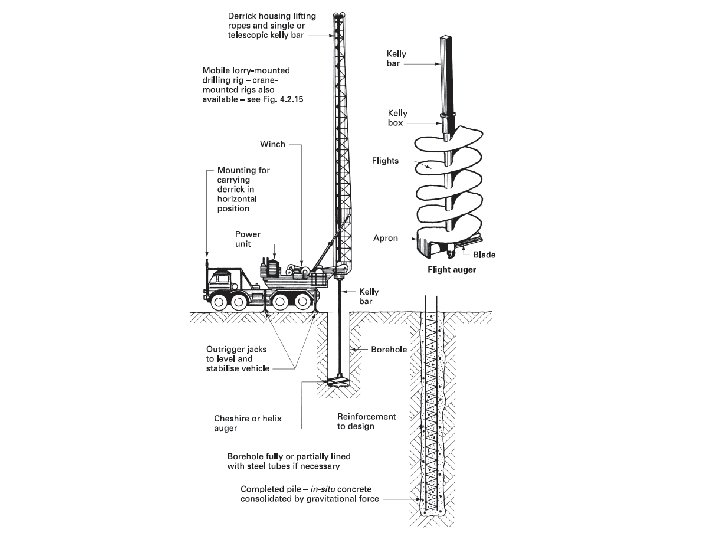

Large-diameter bored piles are usually considered to be those over 750 mm, and can be formed with diameters up to 2. 600 m with lengths ranging from 24. 000 to 60. 000 m to carry loadings from 2, 500 to 8, 000 k. N. They are suitable for use in stiff clays for structures having highly concentrated loadings, and can be lined or partially lined with steel tubes as required. The base or toe of the pile can be enlarged or under-reamed up to three times the shaft diameter to increase the bearing capacity of the pile. Reinforcement is not always required, and the need for specialists’ knowledge at the design stage cannot be overemphasised. Compaction of the concrete, which is usually placed by a tremie pipe, is generally by gravitational force (see Fig. 4. 2. 15). Test loading of large-diameter bored piles can be very expensive, and if the local authority insists on test loading it can render this method uneconomic.

Well and caisson: Types – sinking method – precautions. These are box-like structures that can be sunk through ground or water to install foundations or similar structures below the water line or table. They differ from cofferdams in that they usually become part of the finished foundation or structure, and should be considered as an alternative to the temporary cofferdam if the working depth below the water level exceeds 18. 000 m. The design and installation of the various types of caisson are usually the tasks of a specialist organisation, but building contractors should have a fundamental knowledge of the different types and their uses. There are four basic types of caisson in general use: • box caissons; • open caissons; • monolithic caissons; • pneumatic or compressed-air caissons.

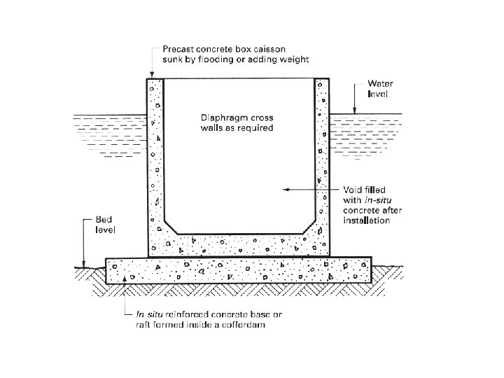
BOX CAISSONS These are prefabricated precast concrete boxes that are open at the top and closed at the bottom. They are usually constructed on land, and are designed to be launched and floated to the desired position, where they are sunk onto a previously prepared dredged or rock foundation. If the bed stratum is unsuitable for the above preparations it may be necessary to lay a concrete raft, by using traditional cofferdam techniques, onto which the caisson can be sunk. During installation it is essential that precautions are taken to overcome the problems of flotation by flooding the void with water or adding kentledge to the caisson walls.

The sides of the caisson will extend above the water line after it has been finally positioned, providing a suitable shell for such structures as bridge piers, breakwaters and jetties. The void is filled with in-situ concrete placed by pump, tremie pipe or crane and skip. Box caissons are suitable for situations where the bed conditions are such that it is not necessary to sink the caisson below the prepared bed level.

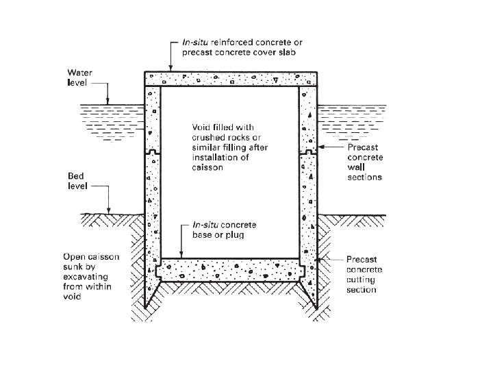
OPEN CAISSONS Sometimes referred to as cylinder caissons because of their usual plan shape, these are of precast concrete and open at both the top and bottom ends, with a cutting edge to the bottom rim. They are suitable for installation in soft subsoils where the excavation can be carried out by conventional grabs, enabling the caisson to sink under its own weight as the excavation proceeds. These caissons can be completely or partially pre-formed; in the latter case further sections can be added or cast on as the structure sinks to the required depth. When the desired depth has been reached a concrete plug in the form of a slab is placed in the bottom by tremie pipe to prevent further leakage of water. The cell void can now be pumped dry and filled with crushed rocks or similar material if necessary to overcome flotation during further construction works.

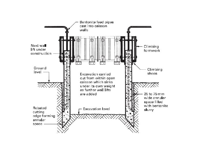
Open caissons can also be installed in land if the subsoil conditions are suitable. The shoe or cutting edge is formed so that it is wider than the wall above to create an annular space some 75 to 100 mm wide into which a bentonite slurry can be pumped to act as a lubricant and thus reduce the skin friction to a minimum. Excavation is carried out by traditional means within the caisson void, the caisson sinking under its own weight. The excavation operation is usually carried out simultaneously with the construction of the caisson walls above ground level.

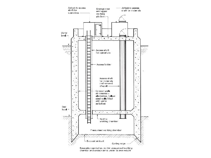
MONOLITHIC CAISSONS These are usually rectangular in plan and are divided into a number of voids or wells through which the excavation is carried out. They are similar to open caissons but have greater self-weight and wall thickness, making them suitable for structures such as quays, which may have to resist considerable impact forces in their final condition. PNEUMATIC OR COMPRESSED-AIR CAISSONS These are similar to open caissons except that there is an airtight working chamber some 3. 000 m high at the cutting edge. They are used where difficult subsoils exist and where hand excavation in dry working conditions is necessary. The working chamber must be pressurised sufficiently to control the inflow of water and/or soil and at the same time provide safe working conditions for the operatives.

The maximum safe working pressure is usually specified as 310 k. N/m 2, which will limit the working depth of this type of caisson to about 28. 000 m. When the required depth has been reached the floor of the working chamber can be sealed over with a 600 mm thick layer of well-vibrated concrete. This is followed by further well vibrated layers of concrete until only a small space remains, which is pressure grouted to finally seal the working chamber. The access shafts are finally sealed with concrete some three to four days after sealing off the working chamber.

Advantages • Economic. • Slightly less noise and reduced vibrations. • Easily adaptable to varying site conditions. • High axial and lateral loading capacity. • Minimal handling equipment is required for placement of reinforcing cage. • Placement is sometimes possible in types of soil that a driven pile could not penetrate

Difference B/W Cofferdam and Caisson 1. 2. 3. 4. 5. Temporary structure A cofferdam becomes uneconomical in cases where the plan area of the foundation work is small as compared to the depth of water. At places where cofferdam cannot be dewatered successfully, caissons are used. The process of constructing a cofferdam is greatly simplified in cases of soils which allow easily the driving of sheet piles. For heavy foundation works which are to be provided at a depth of about 12 to 15 metre below the level of standing water surface coffer dam become uneconomical 1. 2. The part of the permanent work Under such circumstances, a caisson would prove to be the most suitable. 3. Caissons are superior in water tight 4. The caissons, on the other hand, are useful where obstructions of boulders would prevent the successful driving of the sheet piles. For heavy foundation works which are to be provided at a depth of about 12 to 15 metre below the level of standing water surface, caissons would prove to be more economical than cofferdams. 5. The choice of construction depends on the following, a. depth of water, b. nature of soil to be penetrated, and c. permeability of soil below foundation level,

Cable anchoring – screw anchor – necessity- applications.

Grouting: Need – materials – techniques – applications – guniting and shotcreting. Grouting is the process of placing a material into cavities in concrete or masonry structure for the purpose of increasing the load bearing capacity of a structure, restoring the monolithic nature of a structural member, filling voids around pre cast connections steel base plates, providing fire stops, stopping leakages, placing adhesives and soil stabilization. GROUT is a mixture of water, cement and optional material like sand, water reducing admixtures, expansion agents and pozzolans. The water to cement ratio is around 0. 5. Fine sand is used to avoid segregation.

Cement grouts In common with all grouting methods, cement grouts are used to form a ‘curtain’ in soils that have high permeability, making temporary exclusion pumping methods uneconomic. Cement grouts are injected into the ground through a series of grouting holes bored into the ground in lines, with secondary intermediate borehole lines if necessary. The grout can be a mixture of neat cement and water, cement and sand up to a ratio of 1: 4, or PFA (pulverised fuel ash) and cement in the ratio of 1: 1 with 2 parts of water by weight. The usual practice is to start with a thin grout and gradually reduce the water: cement ratio as the process proceeds, to increase the viscosity of the mixture.

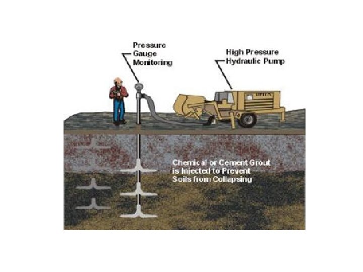
Grout injection Grouts of all kinds are usually injected into the subsoil by pumping in the mixture at high pressure through tubes placed at the appropriate centres according to the solution being used and/or the soil type. Soil investigation techniques will reveal the information required to enable the engineer to decide upon the pattern and spacing of the grout holes, which can be drilled with pneumatic tools or tipped drills. The pressure needed to ensure a satisfactory penetration of the subsoil will depend upon the soil conditions and results required, but is usually within the range of 1 N/mm 2 for fine soils to 7 N/mm 2 for cement grouting in fissured and jointed rock strata.

Clay/cement grouting This is suitable for sands and gravels where the soil particles are too small. The grout is introduced by means of a sleeve grout pipe, and as for the cement grouting the equipment is simple and can be used in a confined space. The clay/cement grout is basically bentonite with additives such as Portland cement or soluble silicates to form the permanent barrier.

Chemical grouting This is suitable for use in medium-to-coarse sands and gravels to stabilise the soil, and can also be used for underpinning works below the water-table level. The chemicals are usually mixed prior to their injection into the ground through injection pipes inserted. – one shot method. The chemicals form a permanent gel in the earth, which increases the strength of the soil and also reduces its permeability. An alternative two-shot method can be used: it is carried out by injecting the first chemical (usually sodium silicate) into the ground and immediately afterwards injecting the second chemical (calcium chloride) to form a silica gel. The reaction of the two chemicals is immediate, whereas in the one-shot method the reaction of the chemicals can be delayed to allow for full penetration of the subsoil, which will in turn allow a wider spacing of the boreholes. One main disadvantage of chemical grouting is the need for at least 2. 000 m of natural cover.

Resin grouts These are suitable for silty fine sands or for use in conjunction with clay/cement grouts for treating fine strata, but like the chemical grouts described above they can be costly unless used on large works. Resin grouts are similar in application to the chemical grouts, but have a low viscosity, which enables them to penetrate the fine sands that are unsuitable for chemical grouting applications. Bituminous grouts These are suitable for injection into fine sands to decrease the permeability of the soil, but they will not increase the strength of the soil, and are therefore unsuitable for underpinning work.

Types of grouting materials and their use • Chemical grouting - control seepage - shut- off seepage - soil stabilization • Cementitious grouting - mass placement - structural(high strength) - caustic environments

Types of grouting materials and their use - high temperatures �Epoxy grouting - seal cracks - bolt anchoring - base plate levelling - acidic environment �Polyesters - bolt anchoring �Silicones - smoke seals - fire stops

Applications of grouting Repairing of cracks • The wide cracks may be repaired by filling them with portland cement grout. • The grout mixture may contain cement and water or cement, sand water, depending upon the width of crack. • The water cement ratio should be kept as low as practicable to maximize strength and minimize shrinkage.

Applications of grouting Strengthening existing walls • The lateral strength of buildings can be improved by increasing the strength and stiffness of the existing individual walls, whether they are cracked or uncracked.

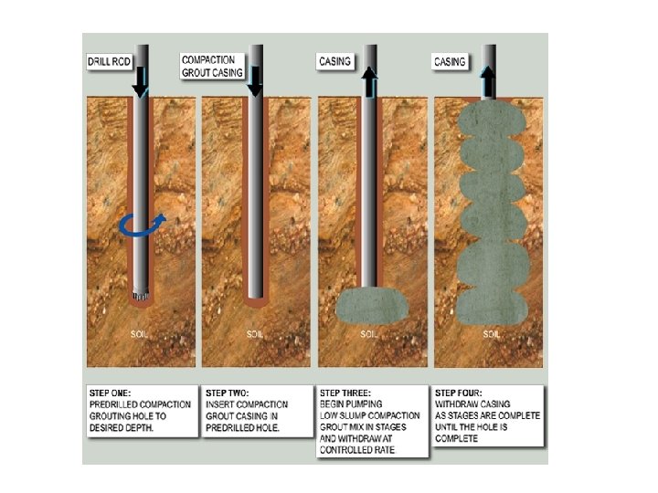
Applications of grouting For soil stabilization • Common methods are - chemical grouting - compaction grouting - jet grouting

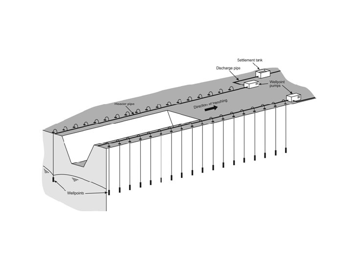
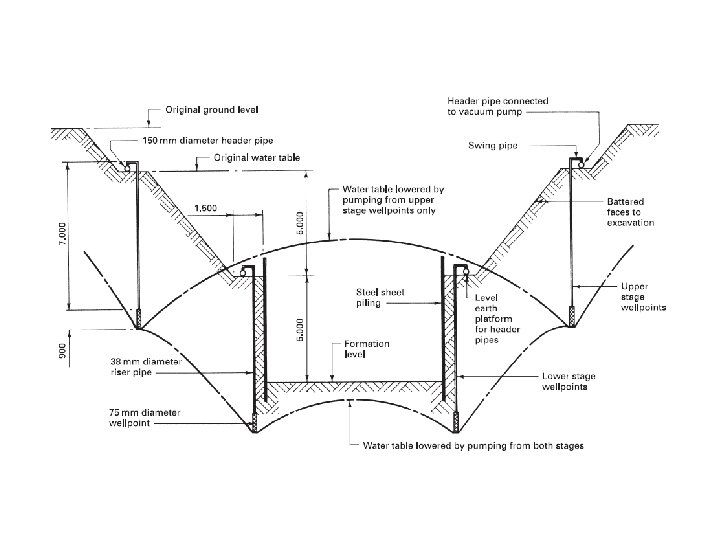
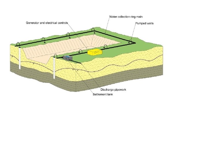
Well points - dewatering – techniques. Wellpoint systems The use of pumping methods to lower the groundwater level is the most widely used and in many cases, the more economical. The groundwater can be directly pumped or allowed to seep to sumps at the boundaries of the excavation site, where it can be pumped from there. These are popular methods for water lowering in non-cohesive soils up to a depth of between 5. 000 and 6. 000 m. To dewater an area beyond this depth requires a multistage installation see Fig. The basic principle is to water-jet into the ground with number of small diameter wells, which are connected to a header pipe attached to a vacuum pump see Fig. Wellpoint systems can be installed with the header pipe acting as a ring main enclosing the area to be excavated. The header pipe should be connected to two pumps, the first for actual pumping operations and the second as a standby pump, because it is essential to keep the system fully operational to avoid collapse of the excavation should a pump failure occur.

A pump is connected to a predetermined length of header pipe, and further well points are jetted in ahead of the excavation works. As the work including backfilling is completed the redundant well points are removed and the header pipe is moved forwards. Shallow-bored wells These are suitable for sandy gravels and water-bearing rocks, and the action is similar in principle to wellpoint pumping but is more appropriate for installations that have to be pumped for several months because running costs are generally lower. This method is subject to the same lift restrictions as wellpoint systems and can be arranged as a multistage system if the depth of lowering exceeds 5. 000 m. Deep-bored wells These can be used as an alternative to a multi-stage wellpoint installation where the groundwater needs to be lowered to a depth greater than 9. 000 m. The wells are formed by sinking a 300 to 600 mm diameter steel lining tube into the ground to the required depth and at spacings to suit the subsoil being dewatered. This borehole allows a perforated well liner to be installed with an electro-submersible pump to extract the water. The annular space is filled with a suitable medium such as sand gravel as the outer steel lining tube is removed (see Fig. 3. 1. 6).

The distance between the well points depends mainly on the hydraulic conductivity and the head of water to be raised. Usually, it ranges between 0. 30 m and 5. 0 m Details of well point system

Dewatering of deep excavation

In excavation works, the presence of groundwater in higher levels, makes the process very complicated. Generally, it is found more practical to lower the groundwater level far enough to make the excavation and other execution works easier. This is done in several ways depending on the original groundwater level, soil properties, importance of the structure and the length of the subsurface construction period. Among the methods of groundwater control are the following: ·dewatering ·freezing ·electro-osmosis ·grouting ·compressed air

Control of Groundwater by Freezing This is one of the most expensive methods of groundwater control. It is actually used when it is practically impossible to use any other method. Double walled Pipes are inserted vertically to the required depth through the soil at distances 1 -1. 5 m center to center around the excavation area. The fluid used to freeze the water is compressed through the inner tube from the freezing plant. The fluid flows back to the plant through the distance between the two walls of the tube. The process of freezing may take several months to be completed. Moreover, the freezing of the bottom of the excavation is far more difficult than the sides.

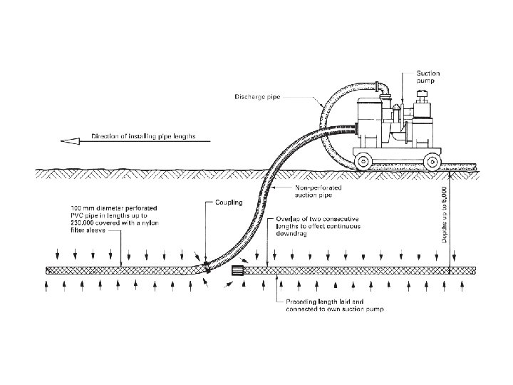
Horizontal groundwater control The pumping methods described above all work on a completely vertical system. An alternative is the horizontal system of dewatering, which consists of installing into the ground a 100 mm diameter PVC perforated suction pipe covered with a nylon filter sleeve to prevent the infiltration of fine particles. The pipe is installed using a special machine that excavates a narrow trench, lays the pipe, and backfills the excavation in one operation at speeds up to 180 m per hour with a maximum depth of 5. 000 m. Under average conditions a single pump can handle approximately 230. 000 m of pipe run; for distances in excess of the pumping length an overlap of consecutive pipe lengths of up to 4. 000 m is required (see Fig. 3. 1. 7).

Electro-osmosis This is an uncommon and costly method, which can be used for dewatering cohesive soils such as silts and clays where other pumping methods would not be adequate. It works on the principle that soil particles carry a negative charge, which attracts the positively charged ends of the water molecules, creating a balanced state; if this balance is disturbed the water will flow. The disturbance of this natural balance is created by inserting into the ground two electrodes and passing an electric charge between them. The positive electrode can be of steel rods or sheet piling, which will act as the anode, and a wellpoint is installed to act as the cathode or negative electrode. When an electric current is passed between the anode and cathode it causes the positively charged water molecules to flow to the wellpoint (cathode), where it is collected and pumped away to a discharge point. The power consumption for this method can vary from 1 k. W/m 3 for large excavations up to 12 k. W/m 3 of soil dewatered for small excavations, which will generally make this method uneconomic on running costs alone.


TALL STRUCTURES CONSTRUCTION Concrete in tall buildings – types of concrete pumps – factors – blockage – causes - clearing –safety. Slip form techniques: Vertical - chimney – horizontal – concrete paving methods. Suspended form work: Purpose –methods – advantages - erection techniques. Prestressing techniques – insitu Prestressing in high rise structures.

Without proper placing procedures, however, even the best designed concrete will segregate and bleed, resulting in honeycombing, poor bond to steel and other despair. Because column and wall forms are usually rather high and reinforcing bars are often spaced quite closely, workmen must be careful in depositing and vibrating concrete in this work. Concrete should be dropped in a true vertical plane and have a free fall of no more than four feet.

CONCRETE PUMPS The advantages of moving large volumes of concrete by using a pump and pipeline are as follows: 1. Concrete is transported from point of supply to placing position in one continuous operation. 2. Faster pours can be achieved with less labour. Typical placing figures are up to 100 m 3 per hour using a two-person crew consisting of the pump operator and an operator at the discharge end. 3. No segregation of mix is experienced with pumping, and a more consistent placing and compaction is obtained, requiring less vibration. 4. Generally, site plant and space requirements are reduced. 5. Available for conveying wet concrete both vertically and horizontally in one operation. 6. No shock loading of formwork is experienced.

Against the above advantages must be set the following limitations: factors 1. Concrete supply must be consistent and regular, which can usually be achieved by well-planned and organised deliveries of ready-mixed concrete. Note that under ideal conditions the discharge rate of each truck mixer can be in the order of 10 minutes. 2. Concrete mix must be properly designed and controlled, because not all concrete mixes are pumpable. The concrete is pumped under high pressure, which can cause bleeding and segregation of the mix: therefore the mix must be properly designed to avoid these problems, as well as having good cohesive, plasticity and self-lubricating properties to enable it to be pumped through the system without excessive pressure and without causing blockages. 3. More formwork will be required to receive the high output of the pump to make its use an economic proposition.
 Most pumps used today are of the twin-cylinder hydraulically driven design, as either")
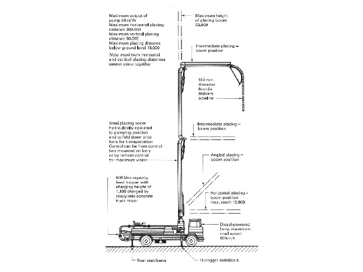
4) Most pumps used today are of the twin-cylinder hydraulically driven design, as either a trailer pump or a lorry-mounted pump using a small-bore (100 mm diameter) pipeline capable of pumping concrete 85 m vertically and 200 m horizontally, although these figures will vary with the actual pump used. 5) The delivery pipes are usually of rigid seamless steel in 3. 000 m lengths except where flexibility is required, as on booms and at the delivery end. 6) Large-radius bends of up to 1. 000 m radius giving, 45° and 90° turning are available to give flexible layout patterns. 7) Generally, small-diameter pipes of 75 and 100 mm are used for vertical pumping, whereas larger diameters of up to 150 mm are used for horizontal pumping. 8) If a concrete mix with large aggregates is to be pumped, the pipe diameter should be at least three or four times the maximum aggregate size.

9. The time required on site to set up a pump is approximately 30 to 45 minutes. 10. The pump operator will require a supply of water and grout for the initial coating of the pipeline: this usually requires about two or three bags of cement. 11. A hard standing should be provided for the pump, with adequate access and turning space for the attendant ready-mixed concrete vehicles. 12. The output of a concrete pump will be affected by the distance the concrete is to be pumped: therefore the pump should be positioned so that it is as close to the discharge point as is practicable. 13. Pours should be planned so that they progress backwards towards the pump, removing the surplus pipe lengths as the work proceeds. 14. Generally, if the volume of concrete to be placed is sufficient to hiring a pump and operators it will result in an easier, quicker and usually cheaper operation than placing the concrete by the traditional method of crane and skip with typical outputs of 15 to 20 m 3 per hour as opposed to the 60 to 100 m 3 per hour output of the concrete pump. Concrete pumping and placing demands a certain amount of skill and experience, and for this reason most pumps in use are hired out and operated

Requirements for pumped concrete Concrete mixture should neither be too harsh nor too sticky; also, neither too dry nor too wet A slump between 50 and 150 mm is recommended (note that pumping induces partial compaction, so the slump at delivery point may be decreased) If the water content in the mixture is low, the coarse particles would exert pressure on the pipe walls. Friction is minimized at the correct water contents. The presence of a lubricating film of mortar at the walls of the pipe also greatly reduces the friction. High cement content in concrete is generally beneficial for pumping. Water is the only pumpable component in the concrete, and transmits the pressure on to the other components
 Water can escape from")
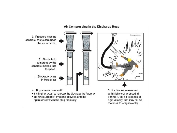
Two types of blockage to efficient pumping could occur: (1) Water can escape from the mixture if the voids are not small enough; this implies that closely packed fines would be needed in the mixture to avoid any segregation. The pressure at which segregation occurs must be greater than that needed to pump concrete. (2) When the fines content is too high, there could be too much frictional resistance offered by the pipe. The first type of blockage occurs in irregular or gap-graded normal strength mixtures, while the second type occurs in high strength mixtures with fillers. In order to avoid these two types of failure, the mixture should be proportioned appropriately. Other mixture factors that could affect pumping are the cement content, shape of aggregate, presence of admixtures such as pumping aids or air entrainment. Air entrainment is helpful in moderate amounts, but too much air can make pumping very inefficient. When flowing concrete is being pumped, an over-cohesive mixture with high sand content is recommended.

The three main causes of concrete pumping system blockages are : • Mix design deficiencies • Pipeline and joint deficiencies • Operating error or careless use of the discharge hose An abrupt reduction in line diameter can cause blockages due to the loss of lubricating grout. Bending a hose too sharply reduces its inside diameter, causing wear to the hose wall and possible blockage.

A flap of loose rubber liner can cause blockage in a discharge hose.

Clearing Blockages All line blockages must be treated care fully. After locating a blockage or rock jam, always make sure the line is no longer under pressure be fore attempting to clear it. Reverse the pump to reduce the pre ss u re. After relieving the system pressure, remove the coupling at the joint nearest the jam. stand to one side. Lift the line so that all the free - flowing concrete runs out. Bend the hose or tap on the pipeline in the area of the jam and shake out loose particles. After the line has been cleaned out, replace the section and resume pumping. If the blockage is in the delivery hose, placing crews should stand clear of the hose until the blockage is cleared. The hose can whip around if the obstruction suddenly moves. Never use compressed air to clear a blockage. It’s unsafe and unnecessary. If a much higher pump pressure can’t move the blockage, air pressure can’t move it either. Any attempt to clear a blockage with air is extremely dangerous.

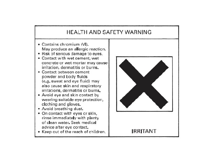
SAFETY NOTE Mortar and concrete contain cement. Mortar may also contain lime. Both ingredients can burn, and skin contact with fresh mortar or concrete may result in skin ulceration and/or dermatitis. Contact with the skin should be prevented by wearing suitable protective clothing – in particular, reinforced plastic gloves, waterproof overalls and footwear and protection for the eyes. Face protection may also be appropriate for certain applications. Where skin contact occurs, immediate washing with soap and water is recommended. Eye contact requires immediate washing of the affected area with clean water. If cement is swallowed, the mouth should be washed out, followed by drinking plenty of clean water. Cement products are packaged with a safety label, similar to that shown in Fig.

Preventive measures to minimize the likelihood of injury. • Only pump concrete that is of a pump able mix. Other mixes of concrete can block the pipeline and cause hose whip. • Start the pump slowly to reduce the likelihood of hose whip • Do not let the concrete solidify in the pipeline as this will cause blockages. The concrete need to remain in its plastic state. • The delivery hose on the boom pump should hang close to vertical and only be guided by the placing crew. If the boom is not long enough to reach the concrete pour area, a larger boom should be used or the pump car should be moved closer to the job. • Do not allow concrete to drop out of the hose when pumping operation is stopped, as this can allow air to enter the system. The hose can be folded over to prevent concrete from dropping out.

Always ensure that the placing crew has an adequate size area to stand on (The width of the working area should be at least 450 mm or greater) the line hand (Personnel guiding the end hose) should not stand on block walls or next to unprotected edges. Monitor the level of concrete in the hopper to avoid air getting sucked into the pump system. Make sure that the hopper still contains concrete before pumping operations has ceased Never try to stretch the delivery hose if it does not reach the pouring location. Make sure work safe procedures are adopted for clearing blockages. When cleaning the pipeline, secure the end of the steel pipeline and have an exclusion zone (No personnel to enter the zone). All reducers and the rubber hose must be removed from the end of the delivery line.

There are basically two types of concrete pumps used for transporting, they are: 1. Direct acting concrete pumps 2. Squeeze type concrete pumps

1. Direct Acting Concrete Pumps • A majority of the concrete pumps are of the directacting, horizontal pistontype with semi-rotary valves. • The operation of the direct- acting pump is simple. • The concrete is fed into the pump by gravity and partly by suction created due to the reciprocating motion of the horizontally-acting piston, while the semirotary valves open and close alternately. Suction pressure of the order of 0. 08 N/mm 2 is developed in

• Best suction conditions are obtained if the diameter of the suction pipe is the same as that of the pumping cylinder so that the concrete can flow unhindered. • Concrete should be able to flow freely through the full cross section of the suction pipe and possible blockages due to over-sized aggregates should be avoided. Ideally, the diameter of the suction pipe should be at least three times the maximum size of the aggregate in the concrete to be pumped. • The diameter of the suction pipe therefore controls the maximum size of aggregate, which can be used in a given mix of concrete to be pumped. • During the ‘suction stroke’ the inlet valve opens and concrete is admitted into the pumping cylinder, the outlet valve remaining closed. • In the ‘delivery stroke’ the outlet valve gets opened and the inlet valve being closed, the concrete gets pushed into the delivery pipeline. • The concrete moves in a series of impulses, the delivery pipe always remaining full. Outputs of up to 60 m 3/h can be achieved in modern pumps through 220 mm diameter delivery pipes.

2. Squeeze type Concrete pumps Squeeze type pumps are smaller portable peristaltic type pumps. The concrete from the collecting hopper is fed by rotating blades into a flexible pipe connected to the pumping chamber, which is under a vacuum of about 0. 08 N/mm 2. The vacuum ensures that, except when being squeezed by the rotating rollers, the pipe shape remains cylindrical and thus permits a continuous flow of concrete. The two rotating rollers mounted on planetary drives progressively squeeze the flexible pipe and thus push the concrete into the delivery pipe. Outputs of up to 20 m 3/h can be obtained with squeeze pumps using 75 -mm diameter pipelines.

Selecting a concrete pump Concrete pumps are selected based on two primary parameters, the maximum desired volumetric output of concrete per hour and the peak pumping pressure, p. A nominal output of 30 m 3/h is considered sufficient for routine concreting operations related to most civil engineering applications. For specialized jobs where greater output is desired, pumps with a capacity in excess of 120 m 3/h have been known to be deployed. The required power of the drive unit (prime mover) of the concrete pump depends on the desired delivery output of concrete, Q, and the pumping pressure, p. The delivery output and the pumping pressure are co-related by the expression for the hydraulic output, H, of the concrete pump:

Slip form techniques: Vertical - chimney – horizontal – concrete paving methods. SLIDING FORMWORK This is a system of formwork that slides continuously up the face of the wall being cast, by climbing up and being supported by a series of hydraulic jacks operating on jacking rods. The whole wall is therefore cast as a monolithic and joint less structure, making the method suitable for structures such as water towers, chimneys and the cores of multi-storey buildings that have repetitive floors. Because the system is a continuous operation, good site planning and organisation are essential, and will involve the following aspects: 1. Round-the-clock working, which will involve shift working and artificial lighting to enable work to proceed outside normal daylight hours. 2. Careful control of concrete supply to ensure that stoppages of the lifting operation are not encountered. This may mean having standby plant as an insurance against mechanical breakdowns. 3. Suitably trained staff accustomed to this method of constructing in-situ concrete walls.

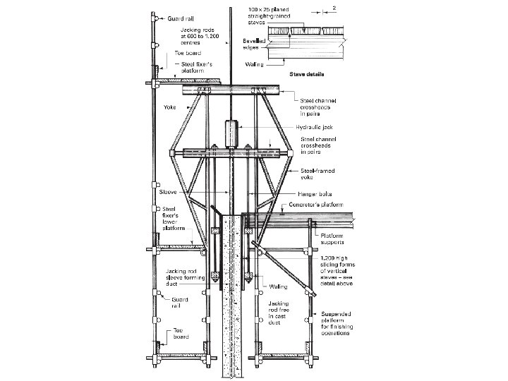
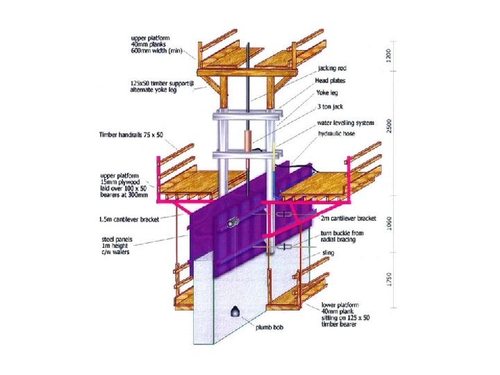
The actual architectural and structural design must be suitable for the application of a slipform system; generally the main requirements are a wall of uniform thickness with a minimum number of openings and a height of at least 20. 000 m to make the cost of equipment, labour and planning an economic proposition. The basic components of slip formwork are: n Side forms These need to be strongly braced, and are load bearing of timber and/or steel construction. Steel forms are heavier than timber, and more difficult to assemble and repair, but they have lower frictional loading, are easier to clean and have better durability. Timber forms are lighter, have better flexibility, are easier to repair and are generally favoured. A typical timber form would consist of a series of 100 mm × 25 mm planed straight-grained staves assembled with a 2 mm wide gap between consecutive boards to allow for swelling, which could give rise to unacceptable friction as the forms rise. The forms are usually made to a height of 1. 200 m with an overall sliding clearance of 6 mm by keeping the external panel plumb and the internal panel tapered so that it is 3 mm in at the top and 3 mm out at the bottom, giving the true wall thickness in the centre position of the form. The side forms must be adequately stiffened with horizontal walings and vertical puncheons to resist the lateral pressure of concrete and transfer the loads of working platforms to the supporting yokes.

Yokes These assist in supporting the suspended working platforms and transfer the platform and side form loads to the jacking rods. Yokes are usually made of framed steelwork suitably braced and designed to provide the necessary bearings for the working platforms. Working platforms Three working levels are usually provided. The first is situated above the yokes at a height of about 2. 000 m above the top of the wall forms for the use of the steel fixers. The second level is a platform over the entire inner floor area at a level coinciding with the top of the wall forms, and is used by the concrete gang for storage of materials and to carry levelling instruments and jacking control equipment. This decking could ultimately be used as the soffit formwork to the roof slab if required. The third platform is in the form of a hanging or suspended scaffold, usually to both sides of the wall, and is to give access to the exposed freshly cast concrete below the slip formwork for the purpose of finishing operations.

Hydraulic jacks The jacks used are usually specified by their loadbearing capacities, such as 3 tonnes or 6 tonnes, and consist of two clamps operated by a piston. The clamps operate on a jacking rod of 25 to 50 mm diameter according to the design load, and are installed in banks operated from a central control to give an all-round consistent rate of climb. The upper clamp grips the jacking rod, and the lower clamp, being free, rises, pulling the yoke and platforms with it until the jack extension has been closed. The lower clamp now grips the climbing rod while the upper clamp is released and raised to a higher position, when the lifting cycle is recommenced. Factors such as temperature and concrete quality affect the rate of climb, but typical speeds are between 150 and 450 mm per hour. The upper end of the jacking rod is usually encased in a tube or sleeve to overcome the problem of adhesion between the rod and the concrete. The jacking rod therefore remains loose in the cast wall and can be recovered at the end of the jacking operation. The 2. 500 to 4. 000 m lengths of rod are usually joined together with a screw joint arranged so that all such joints do not occur at the same level.

A typical arrangement of sliding formwork is shown diagrammatically in Fig. 9. 1. 4. The site operations commence with the formation of a substantial kicker 300 mm high incorporating the wall and jacking rod starter bars. The wall forms are assembled and fixed together with the yokes, upper working platforms and jacking arrangement, after which the initial concrete lift is poured. The commencing rate of climb must be slow, to allow time for the first batch of concrete to reach a suitable condition before emerging from beneath the sliding formwork. A standard or planned rate of lift is usually reached within about 16 hours after commencing the lifting operation. Openings can be formed in the wall by using framed formwork with splayed edges, to reduce friction, tied to the reinforcement. Small openings can be formed using blocks of expanded polystyrene, which should be 75 mm less in width than the wall thickness so that a layer of concrete is always in contact with the sliding forms to eliminate friction. The concrete cover is later broken out and the blocks removed. Chases for floor slabs can be formed with horizontal boxes drilled to allow the continuity reinforcement to be passed through and to be bent back within the thickness of the wall so that when the floor slabs are eventually cast the reinforcement can be pulled out into its correct position.

Types of Slip-form Construction 1 - Vertical Slip-form In vertical slip forming, the concrete form may be surrounded by a platform on which workers stand, placing steel reinforcing rods into the concrete and ensuring a smooth pour. Together, the concrete form and working platform are raised by means of hydraulic jacks. Generally, the slip-form rises at a rate which permits the concrete to harden by the time it emerges from the bottom of the form. 2 - Horizontal Slip-form In horizontal slip forming for pavement and traffic separation walls, concrete is cast, vibrated, worked, and settled in place while the form itself slowly moves ahead. This method was initially devised and utilized in Interstate Highway construction initiated during the 1950 s.

HORIZONTAL FORMWORK • Slipform methods of construction can also be adapted to horizontal structures and are used for paving, canals, and tunneling. • The technique is more in use for structures that have continuous walls like silos , chimneys, and piers for very tall bridges. • It has also been successfully used for construction of buildings, although this requires the manner of leaving inserts for openings like doors and windows to be decided well in advance, as well as also any necessary inserts to support floor slabs after the walls are constructed.

Slipformed Concrete In the slipforming method, the formwork is moved continuously in sync with the concreting process in a 24 -hour operation. The formwork, including the working platform and the hanging scaffold mounted internally or on both sides, is fixed to the jacking rods in the centre of the wall. The hydraulic lifting jack raises the formwork by 10 to 30 cm per hour depending on the temperature. The jacking rods are located in pipe sleeves at the top and are supported by the concrete that has already hardened. The rods and sleeves are also raised continuously. These works are carried out almost entirely by specialist contractors. Slipforming is quick and efficient. The method is particularly suitable for simple, consistent ground plans and high structures such as: � High bay warehouses, silos � Tower and chimney structures � Shaft structures Because the height of the formwork is usually only around 1. 20 m and the hourly production rate is 10 to 30 cm, the concrete underneath is 4– 6 hours old and must be stiff enough to bear its own weight (green strength). However, it must not have set enough for some of it to stick to the rising formwork (“plucking”). The main requirement for slipforming without problems is the ability to place the concrete uniformly as quickly as possible, to ensure that each layer gains "zero slump" within a given timescale. Therefore careful planning, appropriate mix design and well controlled production of a consistent concrete (slump/flow and water/ cement ratio) are essential.

The Benefits of Tilt-up Construction Factor Description 1. Time High production rates can be achieved by careful planning of construction process. 2. Durability Better concrete; a joint less and watertight structure. 3. Cost Slip forms showed cost advantages for more than 20 stories and larger than 600 m 2 formed area per floor. 4. Maintenance Availability of the different working platforms in the formwork system allows the exposed concrete at the bottom of the rising formwork to be finished, making it an integral part of the construction process. 5. Flexibility Certain formwork systems permit construction of tapered cores and towers. 6. Labor Slip form systems require a few but highly skilled workers. 7. Machinery Slip form construction minimizes crane use.

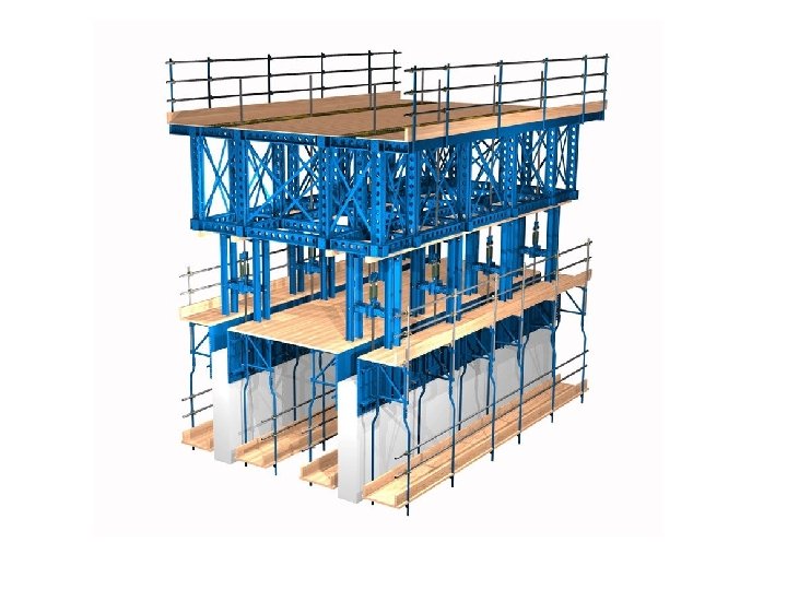
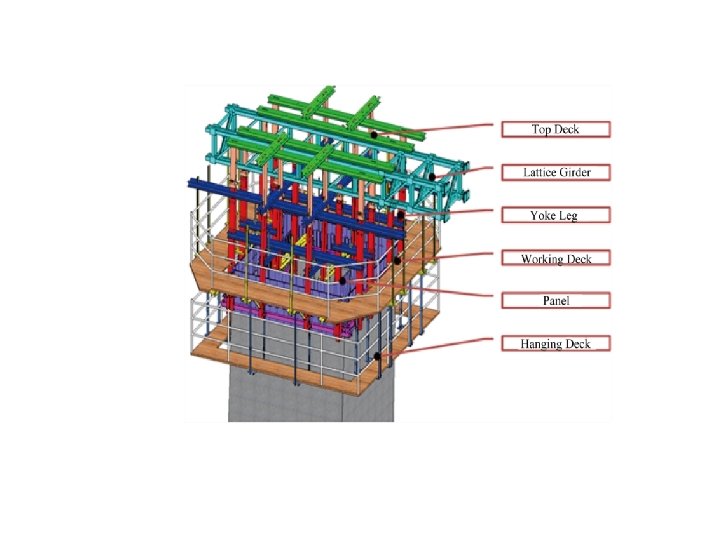
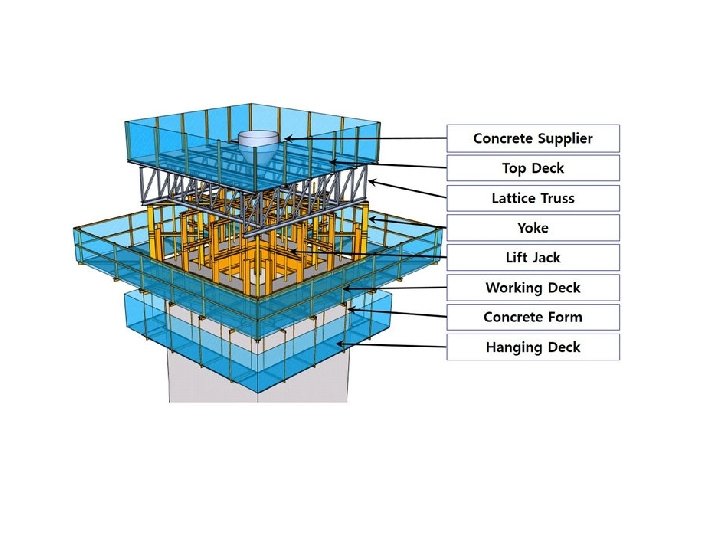
The Slip-form Rig The slip form rig includes three working levels, or decks as follows: 1. The uppermost deck is used to install vertical reinforcing steel and to facilitate placement of the concrete. 2. The middle deck is the main working platform. It provides the locations where gates, ladder platforms, and maintenance decks are formed. Usually , the middle deck supports the hydraulic lifting system as well as provides an area where reinforcing steel is assembled and concrete is poured and vibrated. 3. The lower deck provides access to the newly exposed concrete so that surface finishing processes can be completed and design specifications can be met.

Construction Sequence 1. The formwork and the access platform are assembled on the ground. 2. The assembly is raised using hydraulic jacks which are mounted on strategically located steel frames to lift the formwork as the concrete is poured into the forms. 3. As the formwork rises continuously, continuous concrete and rebar supply are needed until the operation is finished. 4. As the formwork is raised, reinforcement is held in the correct position using guides, horizontal reinforcement is tied to the vertical reinforcement. 5. Concrete is poured into the forms in layers of approximately 200 mm. The setting rates of concrete are constantly monitored to ensure that it is matched with the speed at which the forms are raised. The jacks lift the form approximately 25 mm per stroke generally producing a slip-forming rate of 300 mm per hour

6. Slipforming can be performed on either a continuous basis (i. e. 24 hours per day), or a discontinuous basis (i. e. pouring to a predetermined height usually within one working day). 7. Blockouts for doors and windows can be formed with either timber or steel. These are in-stalled as the slipform proceeds and can be stripped from the trailing decks. 8. Recesses are made to host the connections between the beams, slabs and the slipform walls 9. When the formed concrete is exposed from the bottom of the steel form panels it can be sponged or treated if required . 10. At the end of the operation the formwork is removed using a crane, the entire process is thoroughly inspected and highly controlled

Tapered Slip-forming is also used in the construction of conical chimneys, cooling towers, piers and other tall concrete structures involving constant or changing thicknesses in walls, diameters and/or shapes A form is used with sections which overlap so that one gradually slides over the other. This is commonly done in chimney construction but it is not satisfactory for architectural concrete because the lap shows. While the tapered slipforming process is similar to that used on the standard slip-forming, it requires greater attention, contractor experience and expertise ensures the success of such projects.

Jump Form Another but similar method that is in use for this type of construction is the “jump form method”. In this method the form work jumps up to the next layer after the bottom layer is cast. The concrete pouring is not continuous as in the slip-form method. Jump forms climb in steps following each concrete pour. This type of construction is more suited to high rise building cores where there are regular floors and joints will not be seen. Another jump form system consists of either fixed diameter or adjustable diameter form sets. Our form set permits diameters from 9 ft. to 110 ft. and varying wall thickness. The jump form is a fully decked work platform which is self-contained and sets up in days. In this jump form construction each ring of forms is 4 ft. tall. Three rings of forms are stacked on top of each other. After the top 4 feet of form is poured, the bottom section is removed and vertically jumped to the new top and then prepared for the next pour. This repetitive process of pouring and jumping up the lower set of forms continues until the structure is topped out.
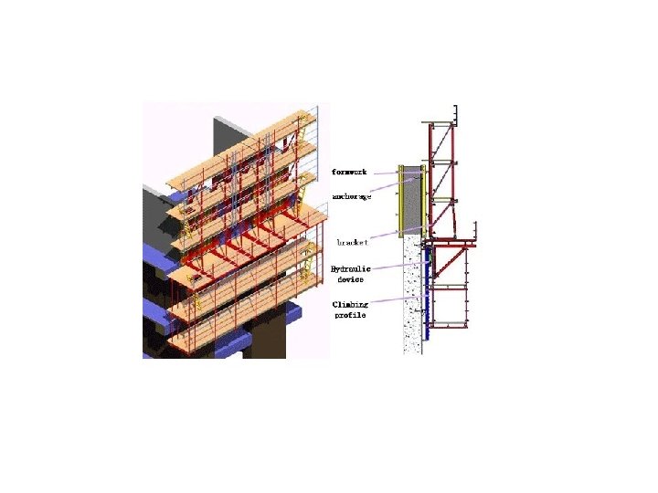

Summary • Slip form construction is a construction method in which concrete is poured into a continuously moving form. • There are two types of slip-forms; vertical and horizontal. • Slip-form construction consumes very less time but requires careful planning of construction process to achieve high production rates. • Due to continuous concrete pouring in slip-form construction it produces better concrete joint less and watertight structures. • Slip form systems require a few but highly skilled workforce. • Slip-forming is also used in the construction of tapered structures involving changing thicknesses in walls, diameters and/or shapes. • Another but similar method that is in use for this type of construction is the “jump form method”. In this method the form work jumps up to the next layer after the bottom layer is cast. The concrete pouring is not continuous as in the slipform method.

Prestressing techniques – insitu The basic principle of prestressing concrete is very simple. If a material has little tensile strength it will fracture immediately its own tensile strength is exceeded, but if such a material is given an initial compression then when load-creating tension is applied the material will be able to withstand the force of this load as long as the initial compression is not exceeded.

PRE-TENSIONING In this method the wires or cables are stressed before the concrete is cast around them. The stressing wires are anchored at one end of the mould and are stressed by hydraulic jacks from the other end until the required stress has been obtained. It is common practice to overstress the wires by some 10% to counteract the anticipated losses that will occur because of creep, shrinkage and relaxation. After stressing the wires the side forms of the mould are positioned and the concrete is placed around the tensioned wires; the casting is then usually steam-cured for 24 hours to obtain the desired characteristic strength, a common specification being 28 N/mm 2 in 24 hours. The wires are cut or released, and the bond between the stressed wires and the concrete will prevent the tendons from regaining their original length, thus inducing the prestress.

At the extreme ends of the members the bond between the stressed wires and concrete will not be fully developed, because low frictional resistance will result in a contraction and swelling at the ends of the wires, forming what is in effect a cone-shape anchor. The distance over which this contraction takes place is called the transfer length and is equal to 80 to 120 times the wire diameter. Usually small-diameter wires (2 to 5 mm) are used so that for any given total area of stressing wire a greater surface contact area is obtained. The bond between the stressed wires and concrete can also be improved by using crimped or indented wires. Pre-tensioning is the prestressing method used mainly by manufacturers of precast components such as floor units and slabs, employing the long line method of casting, where precision metal moulds up to 120. 000 m long can be used with spacers or dividing plates positioned along the length to create the various lengths required; a typical arrangement is shown in Fig. 10. 1. 4.

- Slides: 175