Unit III Piping Components Outline Piping component Hydraulic

 and Pneumatic (copper, steel, plastic) • Piping")


 are used with a")
 are used on piping fitted")


- Slides: 52
Unit – III Piping Components
Outline • Piping component: Hydraulic (Metallic, plastic) and Pneumatic (copper, steel, plastic) • Piping components- • • Mufflers, Reducers, Silencer (Mufflers) Bends, tees (equal, unequal), flanges, couplings (spring loadedthreaded).
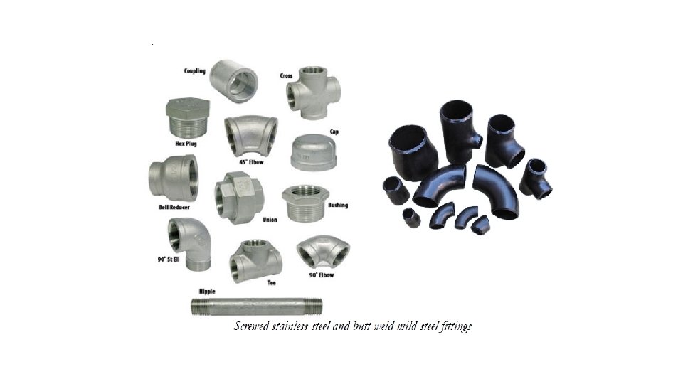
What is Pipe Fittings? • Pipe Fittings are Piping component that helps • • in Changes the direction of the flow such as elbows, tees. Changes the size of the pipe such as reducers, reducing tees. Connect different components such as couplings and Stops the flows such as Caps. • There are different types of pipe fitting used in piping. Pipe Fittings used in piping work are mainly Elbow, Tee, Reducer, Union, Coupling, Cross, Cap, Swage Nipple, Plug, Bush, Expansion Joint, Adapters, Olet (Weldolet, Sockolet, Elbowlet, Thredolet, Nipolet, Letrolet, Swepolet), Steam Traps, Long Radius Bend, Flanges and Valve.
What is Pipe Fittings?
Mufflers A cutaway muffler showing the interior pipes and chambers A muffler cut open to show the insulation, chambers and piping inside the shell
Mufflers • Muffler is a device through which the exhaust gases from an internal-combustion engine are passed to attenuate (reduce) the airborne noise of the engine. • To be efficient as a sound reducer, a muffler must decrease the velocity of the exhaust gases and either absorb sound waves or cancel them by interference with reflected waves coming from the same source. • A typical sound-absorbing material used in a muffler is a thick layer of fine fibres; the fibres are caused to vibrate by the sound waves, thus converting the sound energy to heat. • Mufflers that attenuate sound waves by interference are known as reactive mufflers. • These devices generally separate the waves into two components that follow different paths and then come together again out of phase (out of step), thus canceling each other out and reducing the sound.
Mufflers • In the typical reactive design shown in the illustration, the arrows indicate the flow of exhaust gas through a set of tubes and chambers inside the muffler. • One important chamber is known as the Helmholtz resonator. This chamber is of a dimension carefully tuned to reflect and cancel sound waves of specified frequencies. • In addition, the tubes can be perforated with small holes that allow the reflection and interference of sound waves of other frequencies. • The result is the attenuation of sound across a range of desired frequencies. • Mufflers of the straight-through type have a single tube with small holes connecting with annular chambers that are frequently stuffed with a sound -absorbing material.
Mufflers • https: //www. youtube. com/watch? v=W 6 d. Is. C_e. GBI • https: //www. youtube. com/watch? v=30 JJSXWKIC 8
Reducer • A reducer reduces the pipe size from a larger to a smaller bore (inner diameter). • Alternatively, reducer may refer to any fitting which causes a change in pipe diameter. • This change may be intended to meet hydraulic flow requirements of the system or adapt to existing piping of a different size. • The length of the reduction is usually equal to the average of the larger and smaller pipe diameters. • Although reducers are usually concentric, eccentric reducers are used as needed to maintain the top- or bottom-of-pipe level.
Reducer Types of reducers Concentric Reducer • Concentric Reducers are used to join pipe or tube sections on the same axis. They provide an in-line conical transition between pressurized pipes of differing diameters. • A pipe reducer can be a single diameter change or a multiple diameter change. • Concentric reducers connect pipes of unequal size but have a common centerline. In other words, it is a type of pipe fitting with different size ends to join pipes of different diameter that joins pipe sections on the same axis. • Concentric reducers are designed with the small and large diameters on opposite ends and joined by a cone shaped transition section.
Reducer Types of reducers Concentric Reducer • Uses of concentric reducers: Some uses of concentric reducers are as follows: Concentric reducers will transition gracefully between the piping and the pump. • The concentric reducers help in transporting slurries or abrasive liquids. • They are useful in services where cavitation is present. • When transporting between flanges or pipes of different ratings and wear protection is necessary, concentric reducers are ideal. • Concentric reducers are used in discharge of the pump.
Reducer Types of reducers Eccentric Reducer • An eccentric pipe reducer fitting is manufactured with the smaller outlet off center to the larger end, which allows it to align with only one side of the inlet. • The reducer must be installed with straight side up so that it can prevent trapping air at the pump suction. The eccentric pipe reducers allow simple connection of different sized pipes. Uses of eccentric reducers: Keeping big pipes and small pipes together. • Reducing noise and vibration at the same time. • Requires less installation space. • Absorbs pipe wall and fluid borne noise. • Less turbulence or material entrapment. • Eccentric reducer are used with flat side up in pump suction to avoid cavitation.
Reducer Eccentric Reducer
Reducer • https: //www. youtube. com/watch? v=cr 5 o. Dx 4 C 0 B 4 • https: //www. youtube. com/watch? v=1 Dpag. OLGI 8 Q
Pipe Elbow • The Elbow is used more than any other pipe fittings. It Provides flexibility to change the pipe direction. • Elbow mainly available in two standard types 90° and 45°. However, it Can be cut to any other degree. Elbows are available in two radius types, Short radius (1 D) and Long radius (1. 5 D). 90 Degree Elbow Pipe • 90 Degree elbow is installed between the pipe to change the direction of the pipe by 90 Degree. Available in long and short radius form. 45 Degree Elbow • 45 Degree elbow is installed between the pipe to change the direction of the pipe by 45 Degree.
Pipe Bend • Long radius pipeline bends are used in fluid transportation line which required pigging. • Due to their long radius and smooth change of direction, pipe bend has very less pressure drop, and smooth flow of fluid & pig is possible. • 3 D and 5 D Pipe bends are commonly available. Here, D is the pipe size.
Miter Bend • Miter bends are not standard pipe fittings they are fabricated from pipes. • Usually, they are preferred for size 10” & above because large size elbow is expensive. • Use of miter bend is restricted to the low-pressure water line. • Miter bend can be fabricated in 2, 3, & 5 pieces.
Returns – 180 Degree Elbow • Returning elbows are used to make a 180º change in direction. • Available in short & long pattern. • Returns are used in the heating coil, heat exchanger, tank vent etc.
Bends • https: //www. youtube. com/watch? v=Dm. Xq. JHbu. RXQ • https: //www. youtube. com/watch? v=s 3 Zg. JNl. Uh 4 U • https: //www. youtube. com/watch? v=FH_IA 8 RO 7 i. M
Pipe Tee • Pipe tee is used for distributing or collecting the fluid from the run pipe. • It is a short piece of pipe with a 90 -degree branch at center. • There are two types of Tee used in piping, • Equal / Straight Tee • Reducing / Unequal Tee.
Pipe Tee Straight Tee • In straight tee, the diameter of the branch is same as the diameter of the Run (Header) Pipe. Reducing Tee • In reducing tee, diameter of the branch size is smaller than the diameter of the Run (Header) Pipe
Pipe Tee Swept tee • A swept tee is where the branch enters the body at an arc and is used to minimize the frictional losses and promote flow in the system. Wye tee • A wye tee is where the branch is stabbed into the body at an angle and is usually used where the branch is a smaller diameter than the main pipe.
Pipe Tee • https: //www. youtube. com/watch? v=x. R-PTmsgvw. Q • https: //www. youtube. com/watch? v=i. Bi 5 nibp 6 mc • https: //www. youtube. com/watch? v=q. FCd 22 e. K 20 I
Flanges What is a Flange? • A flange is a method of connecting pipes, valves, pumps and other equipment to form a piping system. • It also provides easy access for cleaning, inspection or modification. • Flanges are usually welded or screwed. • Flanged joints are made by bolting together two flanges with a gasket between them to provide a seal.
Flanges Flange designs are available as: • Weld neck • Slip-on • Socket Weld • Threaded • Stub-end or Lap flange • Blind Flange
Flanges Weld neck • Weld neck flanges are used in critical applications. These are circumferentially welded onto the system at their necks which means that the integrity of the butt-welded area can easily be examined by X -ray radiography. • The bores of both pipe and flange match thus reducing turbulence and erosion.
Flanges There are two types of weld neck flanges, which are standard and long. Standard weld neck flanges are used in butt weld fittings. Long weld neck flanges are used with vessel nozzles and equipment.
Flanges • Socket Flange • A socket flange is counter-bored to accept the pipe, which is then fillet welded. • The bore of both the pipe and the flange are the same to ensure good flows.
Flanges • Socket Flange The Socket weld flanges are attached by only one fillet weld, only on outside, and are not recommended for severe services. These are used for small-bore lines only. The image shows you the X measure for the expansion gap. The disadvantage of socket weld flange is right the gap, that must be made
Flanges • Slip-On Flange • A slip-on flange is slipped over the pipe and then fillet welded. Easy to use in fabricated applications.
Flanges • Slip-On Flange The Slip On type flanges are attached by two fillet welds, inside as well as outside the flange. The disadvantage of the flange is that a combination of flange and elbow or flange and tee is not possible because named fittings have not a straight end that complete slid in the Slip On flange.
Flanges • Screwed Flange • A screwed or threaded flange requires no welding and is used to connect other • threaded components in low pressure non-critical applications.
Flanges • Screwed Flange The Screwed or Threaded flanges are used on pipe lines where welding cannot be carried out. A threaded flange or fitting is not suitable for a pipe system with thin wall thickness, because cutting thread on a pipe is not possible. Thus, thicker wall thickness must be chosen.
Flanges • Lap Flange • Lap flanges (or backing flanges) are used with a stub end which is butt-welded to the pipe with the lap flange acting as a loose collar behind it. • Thus the stub end always provides the sealing face. This type of joint is easily assembled and aligned, and it is favored in low pressure applications. • To reduce costs the ‘backing’ flanges can be made from a lower grade of material such as stainless steel.
Flanges • Lap Flange Lap Joint Flanges (LJ Flanges) are used on piping fitted with lapped pipe or with lap joint stub ends the combined initial cost of the two items being approximately one-third higher than that of comparable welding neck flanges.
Flanges • Blind Flange • A blind flange or sometimes called a blanking flange, this is used for blanking off pipelines, valves and pumps and as an inspection cover.
Flanges • Blind Flange Blind flange are put at the end of pipes or at the junction that would possibly be a future expansion into that direction
Flanges • Applications: • In many applications, engineers need to find a way to close off a chamber or cylinder in a very secure fashion, they do this by fastening two pieces of metal or other material together with a circle of bolts on a lip. This “lip” is a flange. • Plumbing • You can connect two sections of metal piping by soldering or welding them together, but pipes connected in this way are very susceptible to bursting at high pressures. A way of connecting two sections of pipe more securely is by having flanged ends that you can connect with bolts. This way, even if gases or liquids build up to high pressures inside the pipe, it will often hold with no problem. • Mechanics • In order to connect two sections of a large, enclosed area, it is often best to used flanges and bolts. An example of this is the connection between the engine and the transmission in an automobile. In this case, both the engine and the transmission contain a number of moving parts that can easily get damaged if they get dust or other small objects inside of them. By connecting the outer casings of the engine and transmission in this way, engineers protect the inner workings of both. • Electronics • Flanges have a specific purpose in cameras and other electronic devices. Though flanges in such items do not usually have to sustain high pressures, they do have to hold tight so they can keep out harmful particles. These flanges are usually found connecting two different materials, such as the glass of a lens and the rest of the body of the camera.
Flanges • https: //www. youtube. com/watch? v=7 Iu. Hmnm-1 Ec • https: //www. youtube. com/watch? v=T 94 c. GUm. R 9 F 8 • https: //www. youtube. com/watch? v=0 p-7 TNl 7 zvs • https: //www. youtube. com/watch? v=e 9 CXNBCk-VU • https: //www. youtube. com/watch? v=ZIg. NSz. Dz_2 k
Coupling • Coupling is a very short length of pipe or tube with either socket or female pipe threads at one or both ends that allows two pipes or tubes of equal or different sizes to be joined together. • The various functions that a Coupling can serve are as follows: • It helps to extend or terminate pipe runs. • It can be used to change pipe size. • It can be used to repair a broken or leaking pipe.
Coupling Categories of Pipe Couplings: Couplings can be categorized into two main groups. • Permanent Coupling and • Removable Coupling • Permanent Coupling: Permanent pipe couplings generally make use of soldering or brazing in the case of steel or copper pipes or adhesives in the case of PVC pipes. These permanent joints, if correctly installed, offer excellent rigidity and sealing characteristics where no future changes in the piping are foreseen. • Removable Coupling: Removable pipe couplings are most often of a threaded design which allows them to be screwed onto the pipes to be joined. The simplest of these is a basic pipe section slightly larger than the pipes to be joined and cut with an internal thread. The ends of the pipes are also threaded, and the coupling is simply sealed with hemp or sealing tape and screwed onto both pipes.
Coupling Types of Pipe Couplings: There are three types of coupling available • Full Coupling • Half Coupling • Reducing Coupling • Compression Coupling • Slip Coupling / Repair Coupling
Coupling • Full Coupling: • Full Coupling is used for connecting small bore pipes. It used to connect pipe to pipe or pipe to swage or nipple. It can be threaded or socket ends types. • A socket weld full coupling is used to join small bore plain end pipes where the pipe spec requirement is socket weld. A threaded full coupling is used to join small bore pipes with threaded ends. If the two ends of a coupling are different (e. g. one BSP threaded and one NPT threaded), then it is usually referred to as an adapter.
Coupling
Coupling • Half Coupling: • Half Coupling is used for small bore branching from a vessel or large bore pipe. It can be threaded or socket type. It has a socket or thread end on only one side. • A socket weld half coupling can be directly welded to large bore pipe, to make a branch connection. It is used to take a small bore pipe branch-off from a large bore pipe where the pipe spec requirement is socket weld in small bore size. A threaded half coupling only has one thread end another end of the coupling should be butt welding end with either a plain end or a bevel end.
Coupling
Coupling • Reducing Coupling: Reducing coupling is used to connect pipes of dissimilar diameters. • A reducing coupling has two different sizes of threads on each side. Reducing couplings are typically used where small process feeder lines are joined into large supply circuits or where small diameter fittings are installed. • Reducing couplings will normally feature a simple, stepped down profile and screw onto the two lengths of pipe in the same way a standard pipe joint does. Welded reducing coupling designs are similar to threaded design but feature no threads. • Compression Coupling: A compression coupling connects two perfectly aligned pipes in which a slotted tapered sleeve is placed over the junction and two flanges are drawn over the sleeve so that they automatically center the pipes and provide sufficient contact pressure.
Coupling • Slip Coupling / Repair Coupling: A slip coupling (sometimes also called a repair coupling) includes two pipes, one of which slides out of the other pipe to a various length. • Slip coupling is deliberately made without any internal stop, to allow it to be slipped into place in tight locations, such as the repair of a pipe that has a small leak due to corrosion or freeze bursting, or which had to be cut temporarily for some reason. • Since the alignment stop is missing, it is up to the installer to carefully measure the final location of the slip coupling to ensure that it is located correctly.
Coupling
Coupling • https: //www. youtube. com/watch? v=a 4 n 8 GI 4 Rtug • https: //www. youtube. com/watch? v=Q 60 smss. Cep. A • https: //www. youtube. com/watch? v=Mk. WQ 9 b. Ae 5 d. A
Assignment