UNIT III Parallel Port Interfacing Content Interfacing of


 converter • It is a device widely used to convert digital pulses")

 • In the MC 1408 (DAC 0808), the")


 on port P")


 Sin θ Vout (Voltage Values sent to DAC Magnitude) (Decimal) 5")


 Detects body heat (infrared energy). Passive infrared")
 Sends out microwave pulses and measures the reflection off a moving object.")


 provides output in the form of 0 and 1, The")

 www. wikinote. org 2) Muhammad Ali Mazidi, Janice Gillispie Mazidi, Rolin D.")
- Slides: 68
UNIT III Parallel Port Interfacing
Content • Interfacing of: DAC, Temperature sensors, Stepper motor, Motion detectors, Relay, Buzzer, Optoisolaters, Design of DAS and Frequency counter: All programs in assembly
Digital-to-analog (DAC) converter • It is a device widely used to convert digital pulses to analog signals. • Two methods of creating a DAC: Ø Binary weighted and R/2 R ladder • The majority of integrated circuit DACs, including the MC 1408 (DAC 0808) used in this use the R/2 R method since it can achieve a much higher degree of precision.
• The first criterion for judging a DAC is its resolution, which is a function of the number of binary inputs. • The common ones are 8, 10, and 12 bits. • The number of data bit inputs decides the resolution of the DAC since the number of analog output levels is equal to 2 n, where n is the number of data bit inputs. • Therefore, an 8 -input DAC such as the DAC 0808 provides 256 discrete voltage (or current) levels of output. • Similarly, the 12 -bit DAC provides 4096 discrete voltage levels.
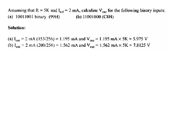
MC 1408 DAC (or DAC 0808) • In the MC 1408 (DAC 0808), the digital inputs are converted to current (Iout), and by connecting a resistor to the Iout pin, we convert the result to voltage. • The total current provided by the Iout pin is a function of the binary numbers at the DO - D 7 inputs of the DAC 0808 and the reference current (Iref), and is as follows:
• where D 0 is the LSB, D 7 is the MSB for the inputs, and Iref is the input current that must be applied to pin 14. The Iref current is generally set to 2. 0 m. A. Figure shows the generation of current reference (setting Iref = 2 m. A) by using the standard 5 -V power supply and IK and 1. 5 K-ohm standard resistors. • Some DACs also use the zener diode (LM 336), which overcomes any fluctuation
How to convert Iout to voltage in DAC 0808? DAC gives output in the form of current, so outside of the DAC current(I) to voltage(V) converter is connected, which is then provided to oscilloscope.
Write an ALP to generate Square wave form on port P 1 of 8051 microcontroller using DAC.
ORG 0000 H MOV P 1, #00 H ; Configure port P 1 as an output port AGAIN: MOV P 1, #FFH ; Logic high level of square wave Acall Delay MOV P 1, #00 H ; Logic low level of square wave Acall DELAY SJMP AGAIN DELAY: MOV R 0, #20 UP 2: MOV R 1, #250 UP 1: MOV R 2, #250 HERE: DJNZ R 2, HERE DJNZ R 1, UP 1 DJNZ R 0, UP 2 RET
Write an ALP to generate Triangular wave form on port P 1 of 8051 microcontrolle r using DAC.
AGAIN: MOV A, #00 H ; Start the triangular wave INCR: MOV P 1, A ; Output value on P 1 INC A ; Increment A for upward transition CJNE A, #0 FFH, INCR ; Check if A= FF, if not keep incrementing DECR: MOV P 1, A ; Output value on P 1 DEC A ; Increment A for upward transition CJNE A, #00 H, DECR ; If A=o, the minimum, step out SJMP AGAIN ; Repeat
Write an ALP to generate Stair-case wave form (with 5 -steps) on port P 1 of 8051 microcontroller using DAC. ØMaximum value is 255. Total number of steps= 5 ØSo increment of each step = 255/5 = 51. ØAfter the maximum value is reached, the output drops to zero and the next cycle starts.
AGAIN: MOV A, #00 H ; To start the staircase wave MOV P 1, A ; Move A to P 1 ACALL DELAY BACK: ADD A, #51 H ; Add 51 to get the next step MOV P 1, A ; Move A to P 1 ACALL DELAY CJNE A, #0 FFH, BACK ; Check if A= FF i. e 255. If not, go to next step till staircase has reached maximum value SJMP AGAIN
Write an ALP to generate Saw tooth wave form MOV A, #00 H ; Start the wave with A=00 MOV P 1, A ; Mov A to P 1 BACK: INC A ; Increment A for transition SJMP BACK
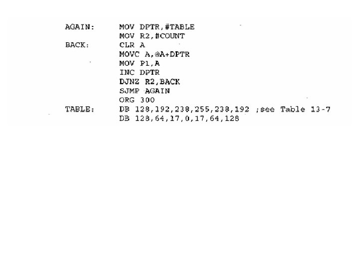
Generating a Sine Wave • To generate a sine wave, we first need a table whose values represent the magnitude of the sine of angles between 0 and 360 degrees. • The values for the sine function vary from -1. 0 to +1. 0 for 0 - to 360 -degree angles. • Table below shows the angles, the sine values, the voltage magnitudes, and the integer values representing the voltage magnitude for each angle (with 30 -degree increments). • To generate this Table, we assumed the fullscale voltage of 10 V for DAC output.
• Full-scale output of the DAC is achieved when all the data inputs of the DAC are high. • Therefore, to achieve the full-scale 10 V output, we use the following equation. Vout = 5 V + (5 V * Sin θ ) • Vout of DAC for various angles is calculated.
Angles θ (Degrees) Sin θ Vout (Voltage Values sent to DAC Magnitude) (Decimal) 5 V + (5 V * Sin θ (Voltage Mag. * 25. 6) ) 0 0 5 128 30 0. 5 7. 5 192 60 0. 866 9. 33 238 90 1. 0 10 255 120 0. 866 9. 33 238 150 0. 5 7. 5 192 180 0 5 128 210 -0. 5 2. 5 64 240 -0. 866 0. 669 17 270 -1. 0 0 0 300 -0. 866 0. 669 17 330 -0. 5 2. 5 64 360 0 5 128
• To find the value sent to the DAC for various angles, we simply multiply the Vout voltage by 25. 60 because there are 256 steps and fullscale Vout is 10 volts. Therefore, 256 steps /10 V = 25. 6 steps per volt.
Sensor Basics • Sensor is any device capable of sensing physical parameters (like temperature, pressure, proximity, etc) and then convert into electrical signals so that it can be used for processing. • Every sensor in this world has three terminals: Ø Vcc – to power up the sensor Ø GND – to provide a fixed negative reference Ø Output – analog output of the sensor (in some sensors, there may be more than one output terminals)
The sensor senses the physical parameters and gives a corresponding output. In most cases the output is analog.
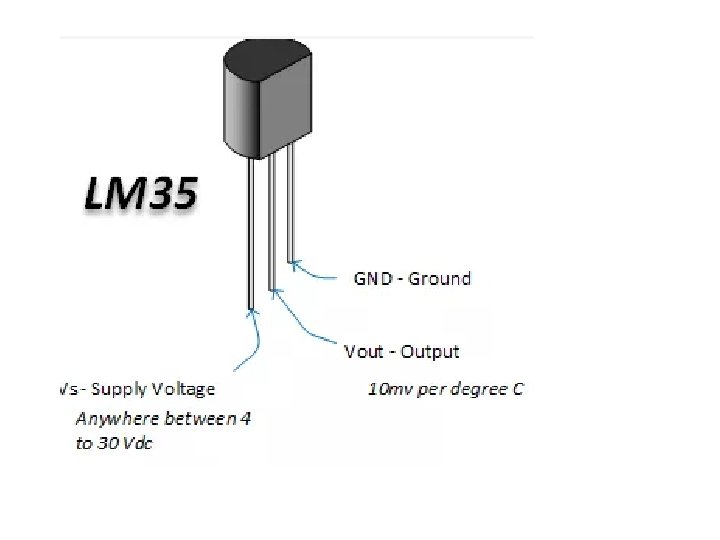
LM 35 Temperature Sensor • LM 35 is a precision centigrade temperature sensor. • It has three terminals – Vcc, Ground and Output. • It has a sensitivity of 10 m. V/°C. This means that for every degree rise in temperature, the output voltage increases by 10 m. V. • In general, it gives a voltage of 0 V at 0°C. Hence, say for an output of 450 m. V, the temperature is 45°C.
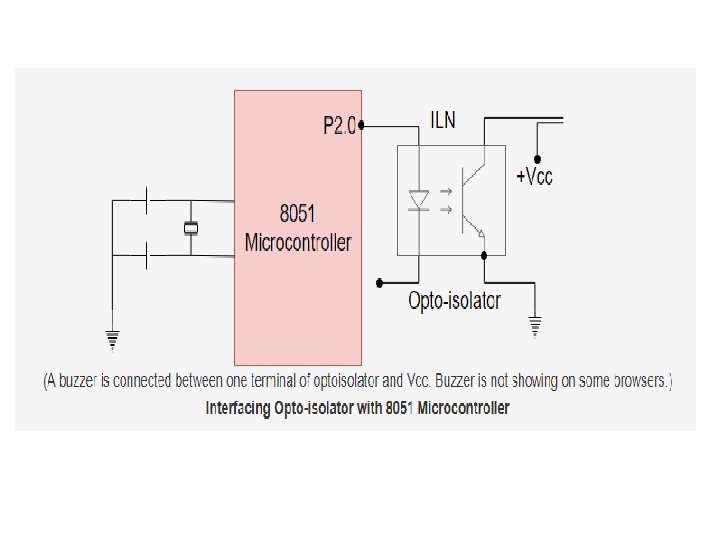
Draw and explain interfacing of Buzzer with 8051 microcontroller, Also write an ALP to interface it to pin P 2. 0 and buzzer should get on when P 2. 0 is High.
ORG 00 H MOV P 3, #00 H AGAIN: SETB P 2. 0 ACALL DELAY CLR P 2. 0 ACALL DELAY SJMP AGAIN DELAY: MOV R 3, #08 H UP 2: MOV R 2, #0 FFH UP 1: MOV R 1, #0 FFHH HERE: DJNZ R 1, HERE DJNZ R 2, UP 1 DJNZ R 3, UP 2 RET END ; Configure Port 3 As Output ; Transistor On, buzzer On ; Transistor Off, buzzer Off
Introduction to Optoisolators In electronics, an opto-isolator, also called an optocoupler, photocoupler, or optical isolator, is a component that transfers electrical signals between two isolated circuits by using light. Opto-isolators prevent high voltages from affecting the system receiving the signal. Commercially available opto-isolators withstand input-to-output voltages up to 10 k. V and voltage transients with speeds up to 10 k. V/μs.
ORG 00 H MOV P 2, #00 H ; Configure Port 3 As Output AGAIN: SETB P 2. 0 ; Led On, Transistor On, Lamp ON ACALL DELAY CLR P 2. 0 ; Led Off, Transistor Off, Lamp Off ACALL DELAY SJMP AGAIN DELAY: MOV R 3, #08 H UP 2: MOV R 2, #0 FFH UP 1: MOV R 1, #0 FFH HERE: DJNZ R 1, HERE DJNZ R 2, UP 1 DJNZ R 3, UP 2 RET END
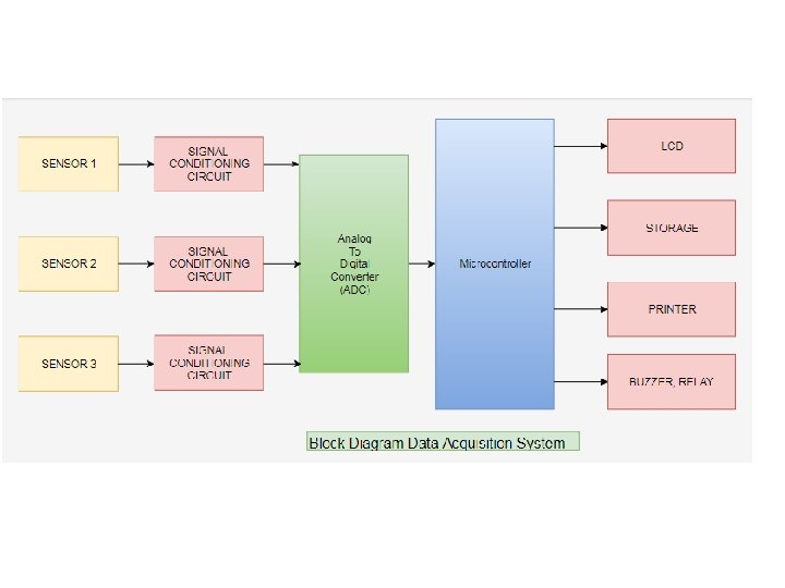
Introduction to Data Acquisition System • Data acquisition systems are widely used in renewable energy source applications in order to collect data regarding the installed system performance, for evaluation purposes. • It consists of Ø Sensors Ø Signal Conditioning Ø Data Conversion Ø Data Processing
• Timer Mode Control Register - TMOD 7 6 5 4 3 2 1 0 G C/T M 1 M 0
Introduction to Frequency Counter Timer Mode Control Register - TMOD 7 6 5 4 3 2 1 0 G C/T M 1 M 0 M 1 and M 0 specify the mode as follows: M 1 0 0 1 M 0 0 1 0 Mode Description in brief Mode 0 13 -bit Timer/counter Mode 1 16 -bit Timer/counter Mode 2 8 -bit Timer/counter with autoreload 1 1 Mode 3 Split Timer 0 into two 8 -bit counters or to stop Timer 1
• If C/T = 1, the timers function as counters to count the negative transitions at T 0 or T 1 pins. • If C/T = 0, the timers function as timers, that is, they basically count the number of machine cycles. • Gate = 0 means that the timer is controlled by TR 1 or TR 0 only, irrespective of INT 0 or INT 1. • Gate = 1 means that the timer control will depend on INT 0 or INT 1 and also on TR 0 or TR 1 bits • When data is written it gets latched. • TMOD is used for setting mode bits M 1, M 0, • Gate bit and C/T for Timer 0 and Timer 1. • Bit 0 to 3 for Timer 0. • Bit 4 to 7 for Timer 1.
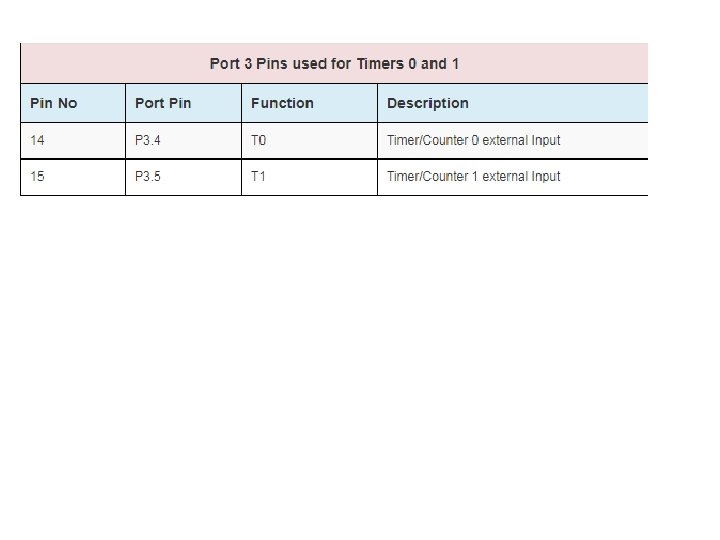
Design a counter for counting the pulses of an input signal. The pulses to be counted are fed to pin P 3. 4. XTAL Freq. = 22 MHz
• In this, Timer 1 is used as base for timing 1 second. During this 1 second, Timer 0 is run as a counter, with input pulses fed into pin P 3. 4. At the end of 1 second, the values in TL 0 and TH 0 give the number of pulses that were received at pin P 3. 4 during this 1 second. This gives frequency of the unknown signal, i. e. , the number of pulses received in 1 second.
ALP for the frequency counter • ORG 00 H Start: MOV TMOD, #15 H ; timer 1 as timer and Timer 0 as counter SETB P 3. 4 ; set P 3. 4 as input pin MOV TL 0, #00 H ; clear TL 0 MOV THO, #00 H ; CLEAR TH 0 SETB TR 0 ; Start counter MOV R 0, #28 ; R 0=28, for time=1 sec
Again: MOV TL 1, #00 H ; MOV TH 1, #00 H SETB TR 1 ; Start timer 1 Back: JNB TF 1, Back ; monitor timer 1 overflow flag CLR TF 1 ; monitor timer 1 overflow flag DJNZ R 0, Again ; repeat the loop until R 0=0 MOV A, TL 0 ; 1 sec time period is finished now save count from TLO in A MOV P 2, A ; send it to port 2 MOV A, TH 0 ; move TH 0 into A MOV P 1, A ; Send it to port P 1 SJMP Start END
Introduction to Stepper-Motor • A stepper motor is an electromechanical device which converts electrical pulses into discrete mechanical movements. • The shaft or spindle of a stepper motor rotates indiscrete step increments when electrical command pulses are applied to it in the proper sequence. • The sequence of the applied pulses is directly related to the direction of motor shafts rotation.
• The speed of the motor shafts rotation is directly related to the frequency of the input pulses and the length of rotation is directly related to the number of input pulses applied. • Stepper motors have a permanent magnet rotor (also called the shaft) surround by a stator. • The most common stepper motors have four stator windings that are paired with a centertapped common. • This type of motor is referred as a four-phase or unipolar stepper.
• Stepper motor shaft moves in a fixed repeatable increment because of the basic magnetic theory where poles of the same polarity repel and opposite poles attract. • The direction of the rotation is dictated by the stator poles. • Stator poles are determined by the current sent through the wire coils. • As the direction of the current is changed, the polarity is also changed causing the reverse motion of the rotor. • As the sequence of power is applied to each stator winding, the rotor will rotate.
Step angle • Movement per step depends on the internal construction of the motor, particularly the number of teeth on the stator and the rotor. • Step angle is the minimum degree of rotation associated with a single step. • Here we consider a stepper motor with 4 leads for the stator winding and 2 COM wires for the center tap.
Stepper motor can be operated in two types of sequences: 1. Half step: In this sequence single coil is energized and then both coils are energized at the same time and motor shaft rotates. Refer figure 1 shown above. Step Angle = 45 degree No of steps = 8 2. Full step: In this sequence single coil is energized or both coils are energized at the same time and motor shaft rotates. Refer figure 1 shown above. Step Angle = 90 degree No of steps = 4
Anti-clockwise Half step Sequence Half Step Sequence Step A B C D Hex Value 1 1 0 0 1 09 H 2 1 0 08 H 3 1 1 0 0 0 CH 4 0 1 0 0 04 H 5 0 1 1 0 06 H 6 0 0 1 0 02 H 7 0 0 1 1 03 H 8 0 0 0 1 01 H Clockwise
Full Step Sequence Clock wise Full step sequence Step A B C D Hex value 1 1 0 08 H 2 0 1 0 0 04 H 3 0 0 1 0 02 H 4 0 0 0 1 01 H Full step sequence Anti-clock wise Step A B C D Hex value 1 0 0 0 1 01 H 2 0 0 1 0 02 H 3 0 1 0 0 04 H 4 1 0 08 H
OR Full Step Sequence Clock wise Full step sequence Step A B C D Hex value 1 1 0 0 1 09 H 2 1 1 0 0 0 CH 3 0 1 1 0 06 H 4 0 0 1 1 03 H Full step sequence Anti-clock wise Step A B C D Hex value 1 0 0 1 1 03 H 2 0 1 1 0 06 H 3 1 1 0 0 0 CH 4 1 0 0 1 09 H
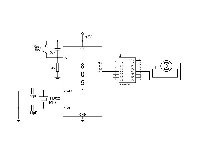
Write a program to rotate stepper motor continuously. • Four leads of the stator winding are controlled by four bits of the 8051 port say(P 1. 0 - P 1. 3). • Since the 8051 lacks sufficient current to drive the stepper motor windings, driver such as ULN 2003 is to be used to energize the stator. • Instead of ULN 2003 transistors can also be used as drivers, but diodes are requires to take care of inductive current generated when the coil is turned off. • ULN 2003 has an internal diode to take care of back EMF.
Program to Rotate Clockwise: MOV A, #66 H; load step sequence BACK: MOV P 1, A ; issue sequence to motor RR A; rotate right - clockwise ACALL DELAY; wait SJMP BACK ; keep going DELAY MOV R 2, #100 H 1: MOV R 3, #255 H 2: DJNZ R 3, H 2 DJNZ R 2, H 1
Program to Rotate Anti-Clockwise: MOV A, #66 H; load step sequence BACK: MOV P 1, A ; issue sequence to motor RL A; rotate left - anticlockwise ACALL DELAY; wait SJMP BACK ; keep going DELAY MOV R 2, #100 H 1: MOV R 3, #255 H 2: DJNZ R 3, H 2 DJNZ R 2, H 1
Write a program to rotate 640 in the clockwise direction. The motor has a step angle of 20. Use the 4 -step sequence. • A motor with 20 step angle has the following characteristics: • Step angle: 20 • Steps per revolution : 180 • Number of rotor teeth : 45 • Movement per 4 -step sequence: 80 • To move the rotor 640 , we have to send eight consecutive 4 -steps, i. e. 32 steps.
ORG 0000 H MOV A, #66 H MOV R 0, #32 BACK: RR A MOV P 1, A ACALL DELAY DJNZ R 0, BACK END
Write an ALP to rotate the stepper motor continuously clockwise using half- sequence or 8 -step sequence. ORG 0000 H START: MOV R 0, #08 MOV DPTR, #0200 H Note: To rotate motor anticlockwise using half RPT: CLR A -sequence or 8 -step MOVC A, @A+DPTR sequence, just reverse MOV P 1, A the sequence i. e. ACALL DELAY send data INC DPTR 01, 03, 02, 06, 0 CH, 08, 09 DJNZ R 0, RPT SJMP START ORG 0200 H ; Sequence values saved in program ROM at 0200 H location DB 09, 08, 0 CH, 04, 06, 02, 03, 01
Write an ALP to rotate the stepper motor continuously clockwise using full sequence or 4 -step sequence. ORG 0000 H START: MOV R 0, #04 MOV DPTR, #0100 H Note: To rotate motor anticlockwise using half RPT: CLR A -sequence or 8 -step MOVC A, @A+DPTR sequence, just reverse MOV P 1, A the sequence i. e. ACALL DELAY send data 1, 2, 4, 8 INC DPTR DJNZ R 0, RPT SJMP START ORG 0100 H ; Sequence values saved in program ROM at 0100 H location DB 8, 4, 2, 1
Introduction to Motion Detectors The main purpose of motion detection is to sense an intruder and send an alert to your control panel, which alerts your monitoring center. Sensors work when you are not home, or when you tell the system you are not there. Some security systems can be programmed to record events via a security camera when motion is detected. Motion sensors stand guard, ready to react to various situations, such as movement in your living room, windows or doors being opened or closed, or a broken window. Motion sensors can: • alert you in the event that your teen breaks curfew • trigger a doorbell when someone approaches the front door • alert you when kids enter restricted areas in the home, like the basement, workout room, or medicine cabinet • save energy by using motion sensor lighting in unoccupied spaces • notify you if pets enter areas where they're not supposed to be
Types of Motion Sensors Passive Infrared (PIR) Detects body heat (infrared energy). Passive infrared sensors are the most widely used motion in home security systems. When your system is armed, your motion sensors are activated. Once the sensor warms up, it can detect heat and movement in the surrounding areas, creating a protective "grid. " If a moving object blocks too many grid zones and the infrared energy levels change rapidly, the sensors are tripped.
Mircowave (MW) Sends out microwave pulses and measures the reflection off a moving object. They cover a larger area than infrared sensors, but they are vulnerable to electrical interference and are more expensive.
Dual Technology Motion Sensors Motion sensors can have combined features in an attempt to reduce false alarms. For example, a passive infrared (PIR) sensor could be combined with a microwave sensor. Since each operates in different areas of the spectrum, and one is passive and one is active, Dual Technology motion sensors are not as likely as other types to cause false alarms, because in order for the alarm to be triggered, both sensors have to be tripped. However, this does not mean that they never cause false alarms.
Area Reflective Type Emits infrared rays from an LED. Using the reflection of those rays, the sensor measures the distance to the person or object and detects if the object is within the designated area. Ultrasonic Sends out pulses of ultrasonic waves and measures the reflection off a moving object. Vibration Detects vibration. These can be purchased or easily made at home. A homemade vibration sensor uses a small mass on a lever, which is activated by a switch to an alarm when it vibrates. Homemade motion sensors can work, but they can also be unreliable.
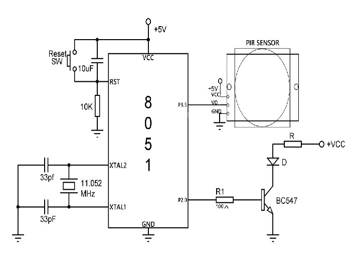
Interfacing PIR sensor(Motion Detector) provides output in the form of 0 and 1, The output of PIR sensor is connected to P 3. 5, So if object detected the output of PIR Sensor will be 1 i. e. High, so that we will turn LED on which is connected to P 2. 0
ALP for the interfacing PIR EQU P 3. 5 LED EQU P 2. 0 ORG 00 H CLR P 2. 0 ; SETB P 3. 5; BACK: JNB PIR, LED_OFF ; LED_OFF: CLR LED JB PIR, LED_ON ; LED_ON: SETB LED SJMP BACK END configure P 2. 0 as output configure P 3. 5 as input PIR=0, Turn-off LED;
References 1) www. wikinote. org 2) Muhammad Ali Mazidi, Janice Gillispie Mazidi, Rolin D. Mc. Kinlay, “The 8051 Microncontroller and Embedded Systems”, Second Editin