UNIT III 8051 Microcontroller The 8051 has two


 Register: • TMOD register, lower 4 bits are set aside for")


- Slides: 49
UNIT – III 8051 Microcontroller
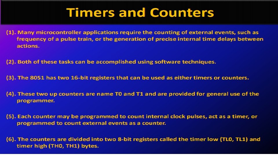
• The 8051 has two timers: timer 0 and timer 1. • Can be used either as timers or as counters. • Both timers are 16 bits wide. • Timer 0 registers is a 16 bits register and accessed as low byte and high byte. • The low byte is referred as a TL 0 and the high byte is referred as TH 0. • These registers can be accessed like any other registers.
Timer 1 registers is also a 16 bits register and is split into two bytes, referred to as TL 1 and TH 1.
TMOD (timer mode) Register: • TMOD register, lower 4 bits are set aside for timer 0 and the upper 4 bits are set aside for timer 1. • In each case, the lower 2 bits are used to set the timer mode and upper 2 bits to specify the operation.
• In upper or lower 4 bits, first bit is a GATE bit. Every timer has a means of starting and stopping. • The hardware way of starting and stopping the timer by an external source is achieved by making GATE=1 in the TMOD register. • If GATE=0 then we do no need external hardware to start and stop the timers. • Second bit is C/T bit and is used to decide whether a timer is used as a time delay generator or an event counter. • If this bit is 0 a timer and if it is 1 then it is used as a counter. • In upper or lower 4 bits, the last bits third and fourth are known as M 1 and M 0 respectively. • These are used to select the timer mode
• Mode 0 - Mode 0 is exactly same like mode 1 except that it is a 13 -bit timer instead of 16 -bit. The 13 - bit counter can hold values between 0000 to 1 FFFH in TH-TL. Therefore, when the timer reaches its maximum of 1 FFH, it rolls over to 0000, and TF is raised. • Mode 1 - It is a 16 -bit timer; therefore it allows values from 0000 to FFFFH to be loaded into the timer’s registers TL and TH. After TH and TL are loaded with a 16 -bit initial value, the timer must be started. • Mode 2 - It is an 8 bit timer that allows only values of 00 to FFH to be loaded into the timer’s register TH. After TH is loaded with 8 bit value, the 8051 gives a copy of it to TL. Then the timer must be started. It is done by the instruction “SETB TR 0” for timer 0 and “SETB TR 1” for timer 1. • Mode 3 - Mode 3 is also known as a split timer mode. Timer 0 and 1 may be programmed to be in mode 0, 1 and 2 independently of similar mode for other timer.
8051 Addressing Modes • Immediate Addressing • Register Addressing • Direct Addressing • Register – Indirect Addressing • Indexed Addressing
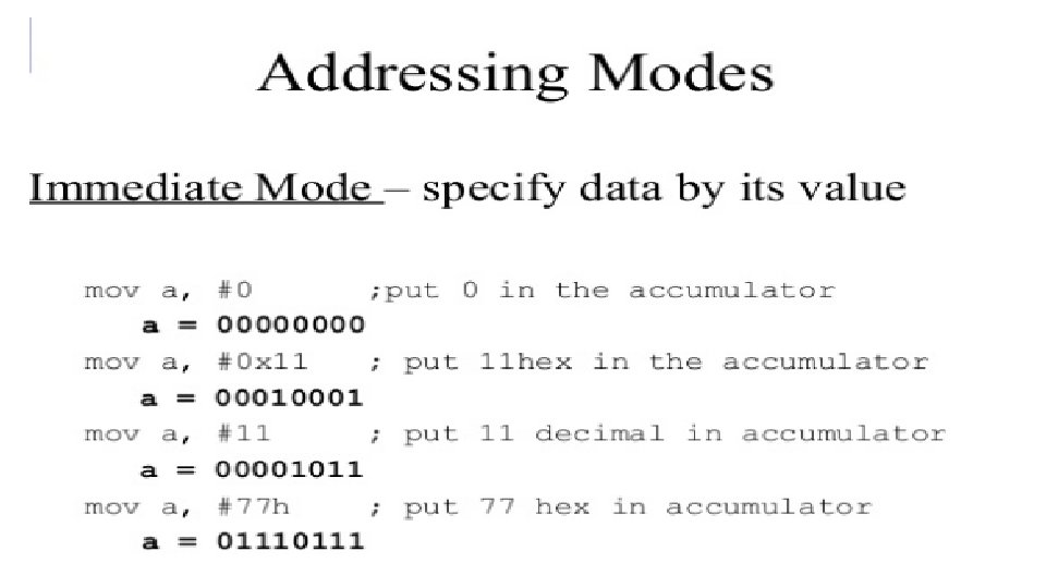
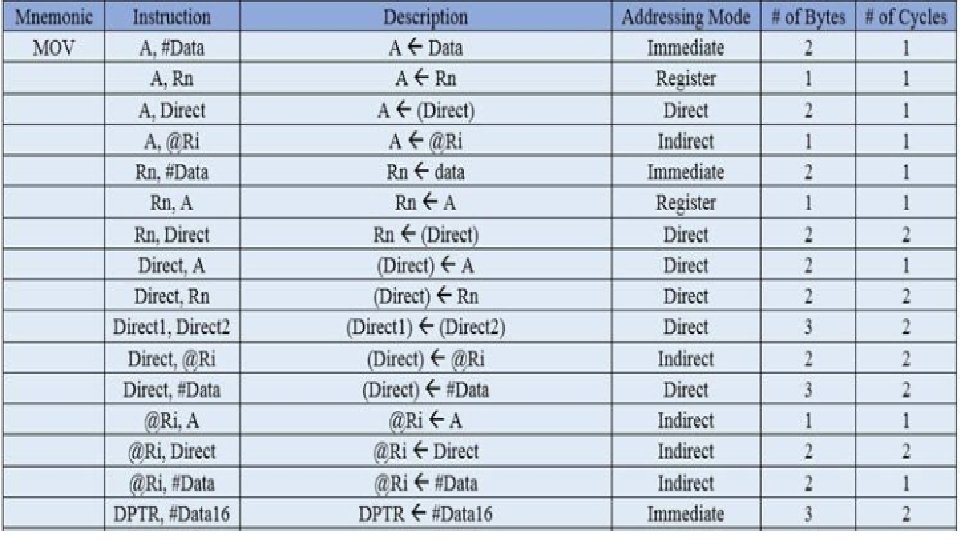
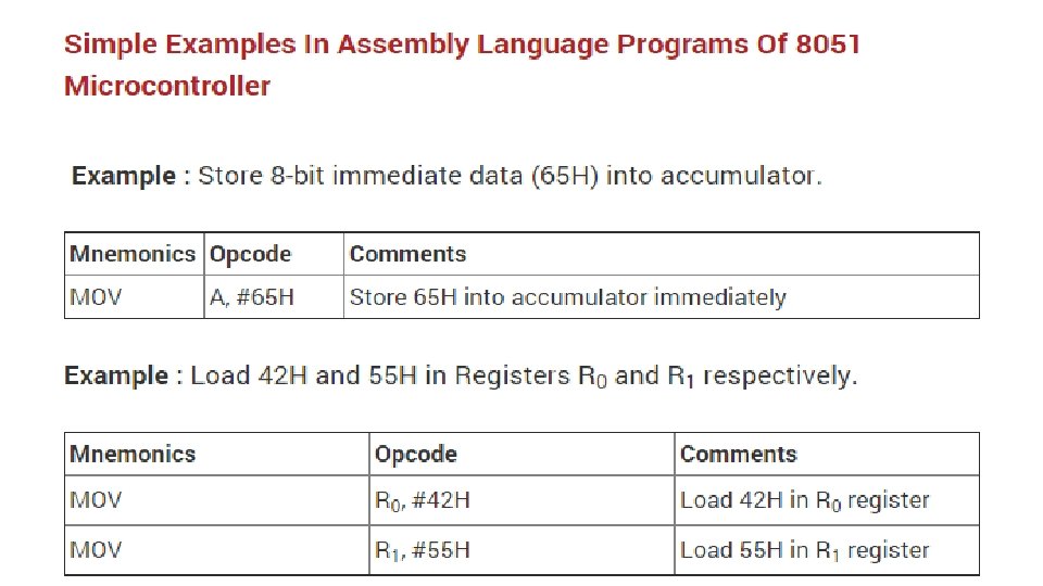
Immediate Addressing • In Immediate Addressing mode, the operand, which follows the Opcode, is a constant data of either 8 or 16 bits. • The name Immediate Addressing came from the fact that the constant data to be stored in the memory immediately follows the Opcode. • Example: MOV A, #030 H • Here, the Accumulator is loaded with 30 (hexadecimal). The # in the operand indicates that it is a data and not the address of a Register.
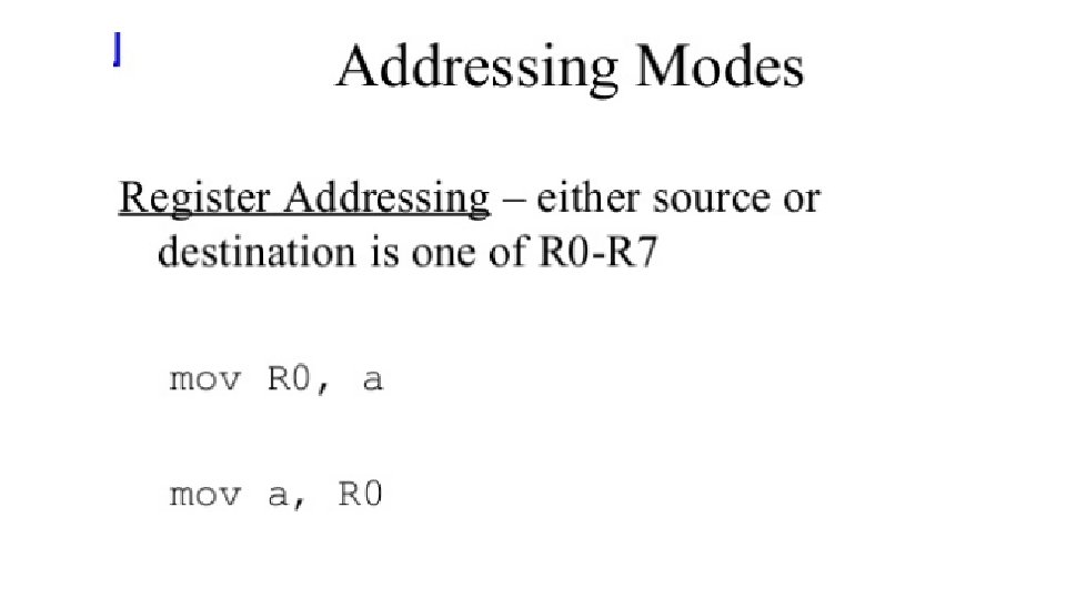
Register Addressing • In Register Addressing mode, one of the eight registers (R 0 – R 7) is specified as Operand in the Instruction. • Example: MOV A, R 5 • Here, the 8 -bit content of the Register R 5 of Bank 0 is moved to the Accumulator.
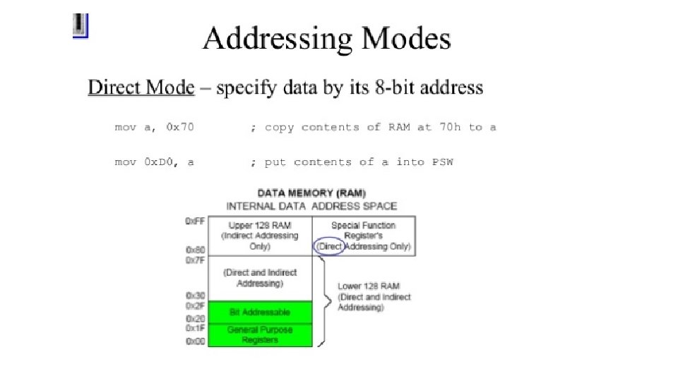
Direct Addressing • In Direct Addressing Mode, the address of the data is specified as the Operand in the instruction. • Using Direct Addressing Mode, we can access any register or on-chip variable. This includes general purpose RAM, SFRs, I/O Ports, Control registers. • Example: MOV A, 47 H • Here, the data in the RAM location 47 H is moved to the Accumulator.
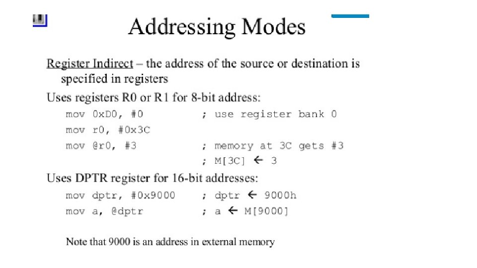
Register Indirect Addressing • In the Indirect Addressing Mode or Register Indirect Addressing Mode, the address of the Operand is specified as the content of a Register. This will be clearer with an example. • Example: MOV A, @R 1 • The @ symbol indicates that the addressing mode is indirect. If the contents of R 1 is 56 H, for example, then the operand is in the internal RAM location 56 H. If the contents of the RAM location 56 H is 24 H, then 24 H is moved into accumulator. • Only R 0 and R 1 are allowed in Indirect Addressing Mode. These register in the indirect addressing mode are called as Pointer registers.
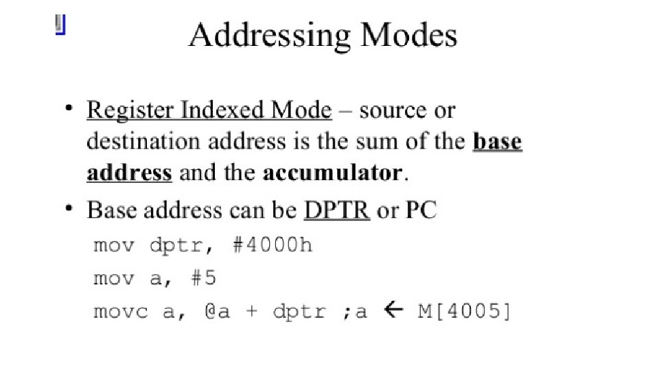
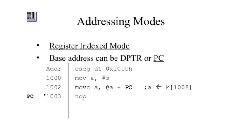
Indexed Addressing Mode • In Indexed Addressing Mode, only MOVC and JMP instructions can be used. Indexed Addressing Mode is useful when retrieving data from look-up tables. • Example: MOVC A, @A+DPTR • Here, the address for the operand is the sum of contents of DPTR and Accumulator.
Types of Instructions in 8051 Microcontroller Instruction Set
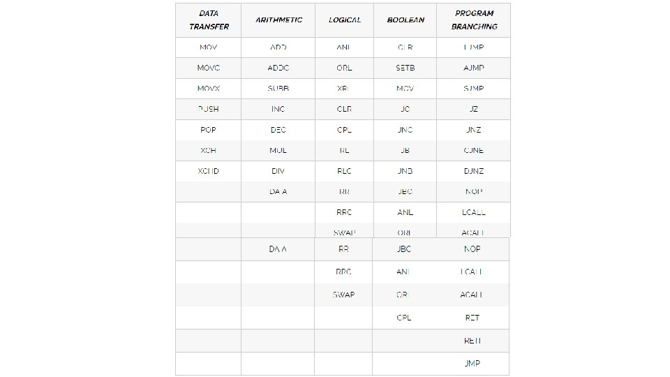
Data Transfer Instructions Based on the operation they perform, all the instructions in the 8051 Microcontroller Instruction Set are divided into five groups. They are: • Data Transfer Instructions • Arithmetic Instructions • Logical Instructions • Boolean or Bit Manipulation Instructions • Program Branching Instructions
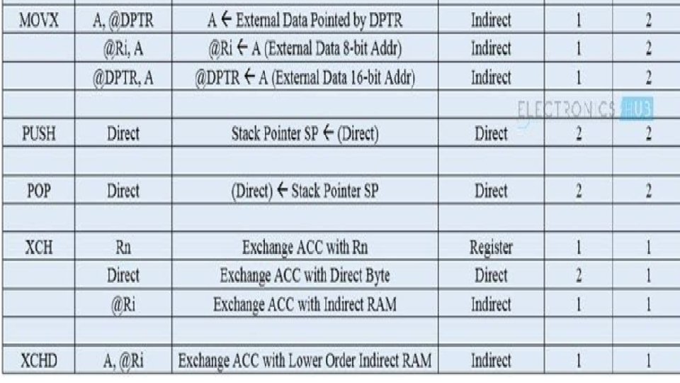
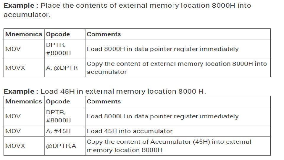
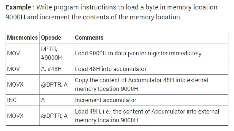
Data Transfer Instructions • MOVC • MOVX • PUSH • POP • XCHD
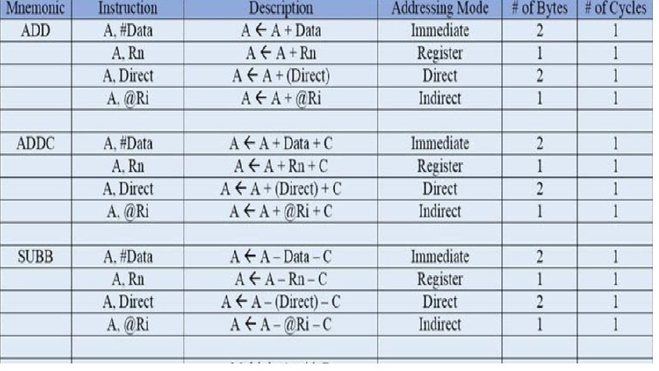
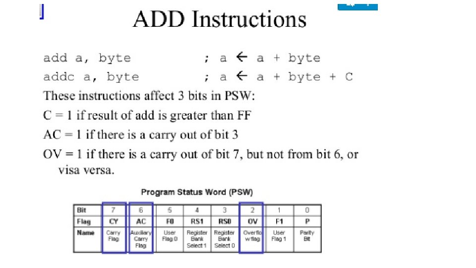
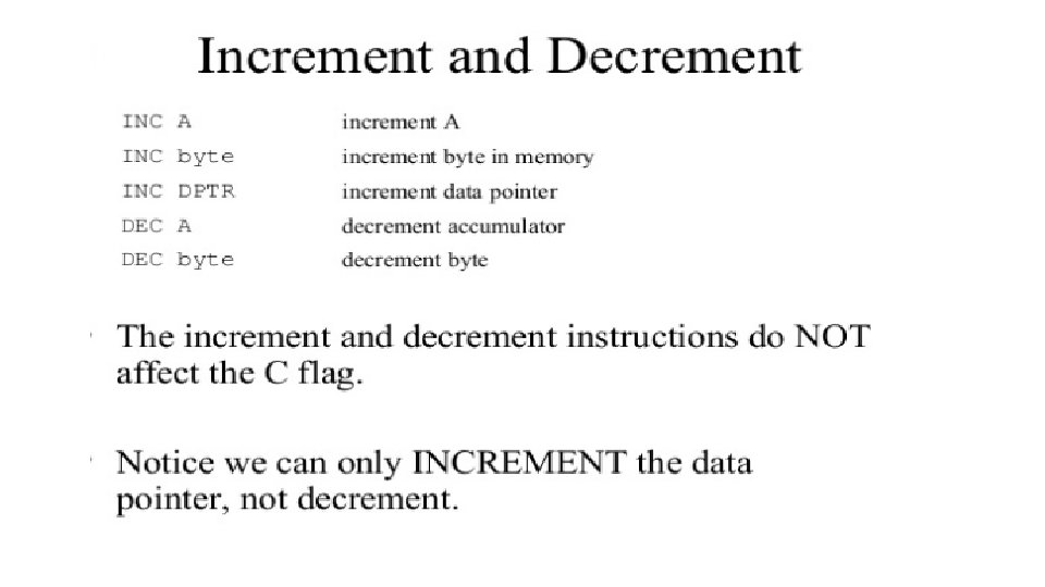
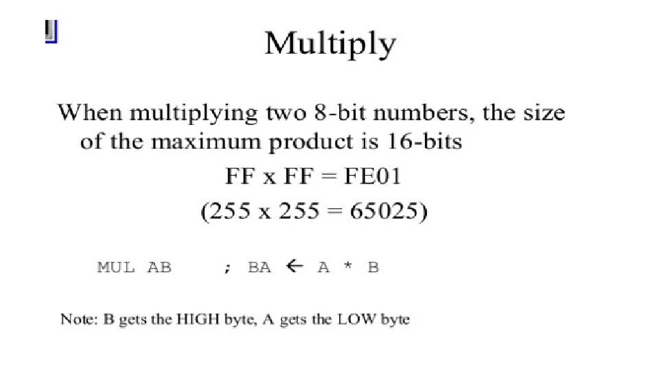
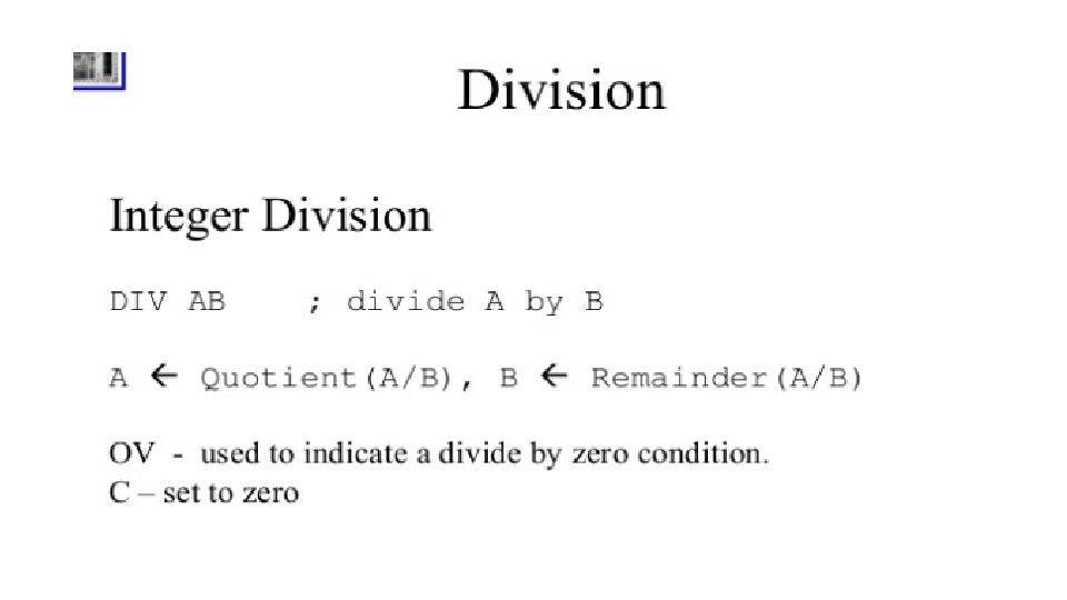
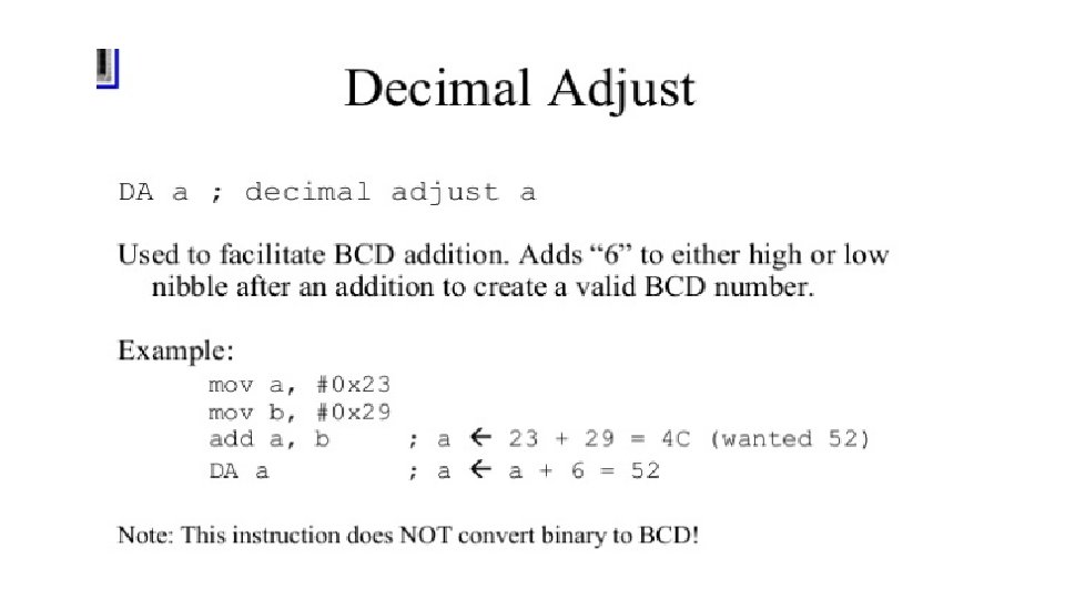
Arithmetic Instructions • The Mnemonics associated with the Arithmetic Instructions of the 8051 Microcontroller Instruction Set are: • ADDC • SUBB • INC • DEC • MUL • DIV • DA A
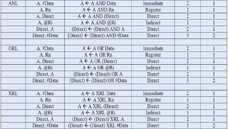
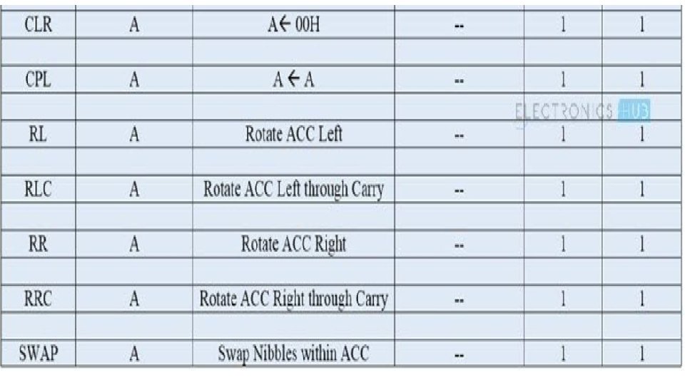
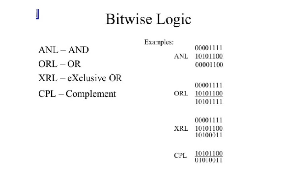
Logical Instructions • ANL • ORL • XRL • CLR • CPL • RLC • RRC • SWAP
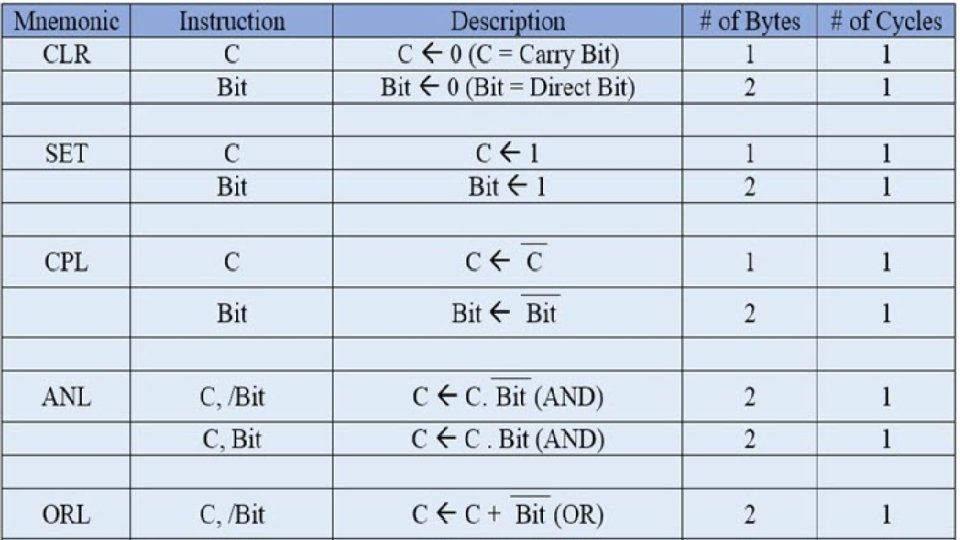
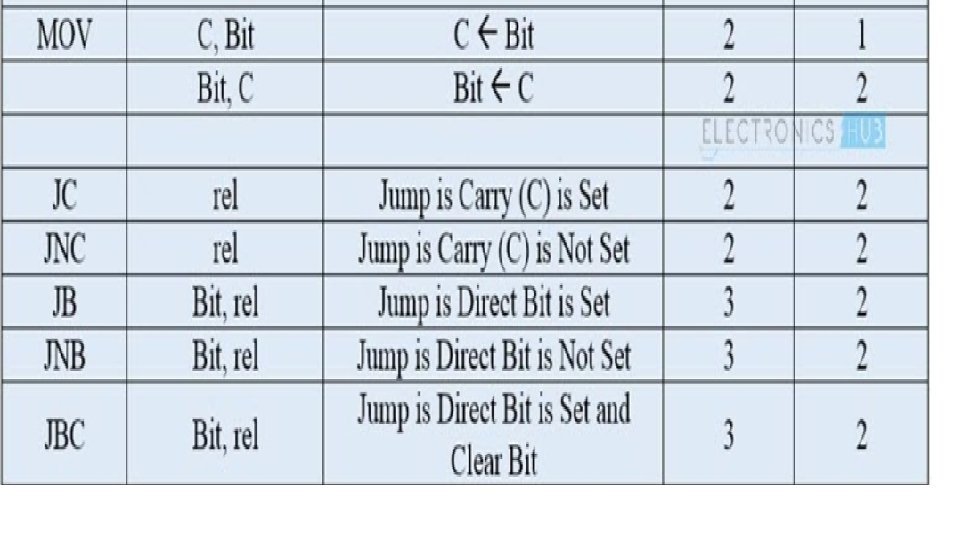
Boolean or Bit Manipulation Instructions • CLR • SETB • MOV • JC • JNC • JB • JNB • JBC • ANL • ORL • CPL
Program Branching Instructions • LJMP • AJMP • SJMP • JZ • JNZ • CJNE • DJNZ • NOP • LCALL • ACALL • RETI • JMP
MOV PSW, #00 H Register bank '0' is selected by executing this instruction. MOV R 0, 35 H The value of 'N' stored in location 35 H is transferred to R 0. MOV R 5, #55 H The starting location for storing natural numbers '#55 H' is transferred to R 5 MOV A, #00 H Accumulator is initiated with value 0 for adding natural numbers cumulatively. MOV R 7, #00 H R 7 is initialized to '0' to generate natural numbers. Note: '0' is not a natural number. LOOP: INC R 7 is incremented by 1 to generate next natural number. MOV R 7, #00 H MOV @R 5, 07 H It is not possible to transfer data from one register to another register directly. So an instruction like MOV R 5, R 7 is invalid. Instead we use the direct address (07) of register R 7 of register bank #00 to transfer the generated natural number to it's storage location in register R 5. INC R 5 The storage location is incremented by 1 from #55 H to #56 H to store the next generated natural number ADD A, R 7 dccxcdddcdxd DJNZ R 0, LOOP MOV 36 H, A STOP: SJMP STOP The generated natural number is added to contents in accumulator. The value of register Ro (value of 'N') is decremented by 1. It is checked against stopping condition zero. The sum of natural numbers in accumulator is moved to storage location 36 H. An infinite loop written at the end of the program. When this instruction is reached program control will get stuck at this instruction as it's an infinite loop.