UNIT II SOIL WATER AND WATER FLOW Soil


 unit")


- Slides: 27
UNIT II. SOIL WATER AND WATER FLOW Soil water – static pressure in water - effective stress concepts in soils – capillary stress – permeability measurement in the laboratory and field pumping in pumping out tests – factors influencing permeability of soils – seepage – introduction to flow nets – simple problems. (Sheet pile and weir). • Chapter 1: Static pressure in soil due to water. • Chapter 2: Permeability in soil • Chapter 3: Seepage in soil -Flow net concept
1. Define soil water Water present in the voids of a soil mass is called soil water. 2. State the types of soil water. i. Free water (or) Gravitational water ii. Held water a. Structural water b. Absorbed water c. Capillary water. 3. Define free water and held water. Free water: Water that is free to move through a soil mass under the influence of gravity is known as free water. Held water: Held water is the part of water held in soil pores by some forces existing within the pores: such water therefore is not free to move under gravitational forces. Structural water: Structural water is the water chemically combined in the crystal structure of the soil mineral and can be removed only by breaking the structure. Adsorbed water: It is the part which the soil particles freely adsorb from atmosphere by the physical forces of attraction and is hold by the force of adhesion. Capillary water: Water held in the interstices of soil due to capillary forces is called capillary water.
4. Define Total pressure, Neutral pressure and Effective pressure. The total stress (or) unit pressure (σ ): Total pressure is the total load per unit area. The total vertical pressure at any plane is equal to the sum of the effective pressure and the pore pressure. Total Pressure = Effective pressure + Neutral pressure σ =σ’+ u Effective pressure (σ’) : Effective pressure is the pressure transmitted from particle through this point of contact through the soil mass above the plane. σ’ = ϒ. h where, ϒ = Unit weigt of soil, h=height of the soil streata The neutral pressure (u) (or) the pore pressure (or) the pore water pressure : Neutral pressure is the pressure transmitted through the pore fluid. U = ϒw. h
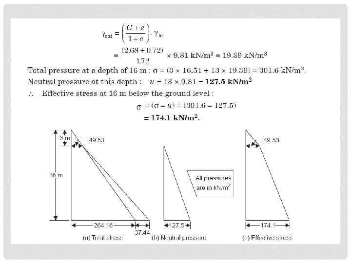
5. Determine the neutral and effective stress at a depth of 16 m below the ground level for the following conditions: Water table is 3 m below ground level ; G = 2. 68; e = 0. 72; average water content of the soil above water table is 8%. Solution:
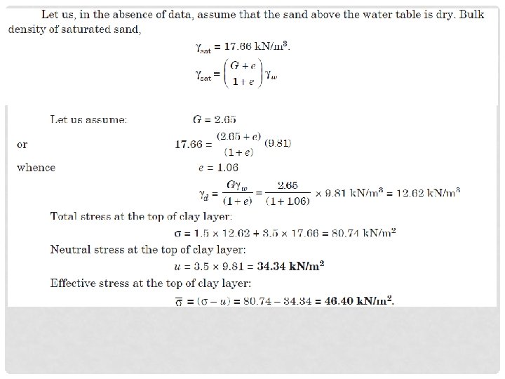
6. A saturated sand layer over a clay stratum is 5 m in depth. The water is 1. 5 m below ground level. If the bulk density of saturated sand is 17. 66 k. N/m 3, calculate the effectiveand neutral pressure on the top of the clay layer.
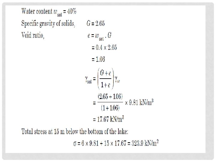
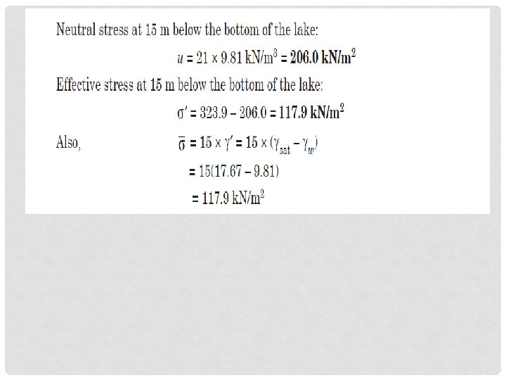
7. Compute the total, effective and pore pressure at a depth of 15 m below the bottom of a lake 6 m deep. The bottom of the lake consists of soft clay with a thickness of more than 15 m. The average water content of the clay is 40% and the specific gravity of soils may be assumed to be 2. 65.
8. Define Darcy’s law states that for laminar flow conditions in a saturated soil, the rate of flow or the discharge per unit time is proportional to the hydraulic gradient. vᾳI v= ki q = v. A q = ki. A k=q/i. A Where q = discharge per unit time, A = Total cross-sectional area of soil mass, perpendicular to the direction of flow, i = hydraulic gradient, i= (h 1 -h 2)/L k = Darcy’s Coefficient of permeability, v = Velocity of flow, or average discharge velocity.
9. State the factors affecting permeability. i. Grain size ii. Properties of the pore fluid iii. Voids ratio of the soil iv. Structural arrangement of the soil particle v. Entrapped air and foreign-matter. vi. Adsorbed water in clayey soils. 10. Mention the methods to determine the coefficient of permeability. a. Laboratory methods i. Constant head permeability test ii. Falling head permeability test b. Field methods i. Pumping – out tests ii. Pumping –in tests 11. Define coefficient of permeability (or) permeability. It is defined as the average velocity of flow that will occur through the total cross sectional are of soil under unit hydraulic gradient. The coefficient of permeability is denoted as K. It is usually expressed as cm/sec (or) m/day (or) feet/day. K=Q/i. A 12. Define seepage velocity (or) Actual velocity. The actual velocity (or) seepage velocity is defined as the rate of discharge of percolating water per unit cross-sectional area of voids perpendicular to the direction of flow. vs = v/n = ki/n, Coefficient of Percolation, kp = k/n
13. Explain Constant head permeability test The constant head test is used primarily for coarse-grained soils. Q=V/t From Darcy’s Law, Q=k. i. A Where: V = volume of water collection A = cross section area of soil specimen T = duration of water collection 13
14. Explain Falling Head permeability Test The water level in the stand-pipe falls continuously as water flows through the soil specimen. Observations should be taken after a steady state of flow has reached. If the head or height of water level in the standpipe above that in the constant head chamber falls from h 0 to h 1, corresponding to elapsed times t 0 and t 1, the coefficient of permeability, k, can be shown to be : The above equation is derived assuming: The flow through the standpipe = flow through the soil 14
Derivation of Falling Head equation
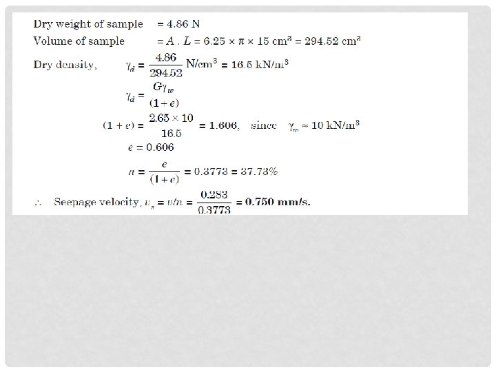
15. The discharge of water collected from a constant head permeameter in a period of 15 minutes is 500 ml. The internal diameter of the permeameter is 5 cm and the measured difference in head between two gauging points 15 cm vertically apart is 40 cm. Calculate the coefficient of permeability. If the dry weight of the 15 cm long sample is 4. 86 N and the specific gravity of the solids is 2. 65, calculate the seepage velocity.
16. Determine the coefficient of permeability from the following data: Length of sand sample = 25 cm Area of cross section of the sample = 30 cm 2 Head of water = 40 cm Discharge = 200 ml in 110 s.
• 17. Explain the permeability test conducted in the field or explain pumping in and out test. • During the test, water is pumped out at a constant rate from a test well that has a perforated casing. Several observation wells at various radial distances are made around the test well. Continuous observations of the water level in the test well and in the observation wells are made after the start of pumping, until a steady state is reached. The steady state is established when the water level in the test and observation wells becomes constant.
PUMPING WELL IN AN UNCONFINED AQUIFER q OR If q, h 1, h 2, r 1, r 2 are known , k can be calculated
PUMPING WELL IN A CONFINED AQUIFER q If q, h 1, h 2, r 1, r 2 are known , k can be calculated
18. An unconfined aquifer is known to be 32 m thick below the water table. A constant discharge of 2 cubic metres per minute is pumped out of the aquifer through a tubewell till the water level in the tubewell becomes steady. Two observation wells at distances of 15 m and 70 m from the tubewell show falls of 3 m and 0. 7 m respectively from their static water levels. Find the permeability of the aquifer. The conditions given are shown in Fig.
• 19. Explain about Flow nets and drawing techniques. • Flow nets are the combination of flow lines and equipotential lines. 1. Flow lines: the line along which a water particle will travel from upstream to the downstream side in the permeable soil medium 2. Equipotential lines: the line along which the potential (pressure) head at all points is equal. Properties of flow net: • 1. The flow lines and equpotential lines meet at right angles to one another. • 2. The fields are approximately squares, so that a circle can be drawn touching all the four sides of the square. • 3. The quantity of water flowing through each flow channel is the same, similarly, the same potential. • 4. Smaller the dimensions of the field, greater will be the hydraulic gradient and velocity of flow through it. • 5. In a homogeneous soil, every transition in the shape of the curves is smooth, being either elliptical or parabolic in shape. 23
Flow Net Drawing Technique 1. Draw to a convenient scale the geometry of the problem. 2. Establish constant head and no flow boundary conditions and draw flow and equipotential lines near boundaries. • Constant head boundaries (water levels) represent initial or final equipotentials • Impermeable (no-flow) boundaries are flow lines 3. Sketch flow lines by smooth curves (3 to 5 flow lines). • Flow lines should not intersect each other or impervious boundary 4. Draw equipotential lines by smooth curves adhering to right angle intersections and square grids conditions (aspect ratio =1). 5. Continue sketching and re-adjusting until you get squares almost everywhere. Successive trials will result in a reasonably consistent flow net. The rate of flow will be, 24
25
21. A deposit of cohesionless soil with a permeability of 3 × 10– 2 cm/s has a depth of 10 m with an impervious ledge below. A sheet pile wall is driven into this deposit to a depth of 7. 5 m. The wall extends above the surface of the soil and a 2. 5 m depth of water acts on one side. Sketch the flow net and determine the seepage quantity per meter length of the wall. Number of flow channels, nf = 4, Number of equipotential drops, nd = 14 27