Unit 5 Pneumatics GAS LAWS 1 Boyles Law

Unit: 5 Pneumatics

GAS LAWS: 1. Boyle’s Law: Statement: If a given mass of a gas is compressed or expanded at a constant temperature, then the absolute pressure is inversely proportional to the volume.

Charles law: Statement: If a given mass of a gas is heated or cooled at a constant pressure, then the volume is directly proportional to the absolute temperature.

Gay-Lussac’s Law : Statement: At constant pressure, the absolute pressure of an ideal gas will vary directly with the absolute temperature
Based on principle of operation:")
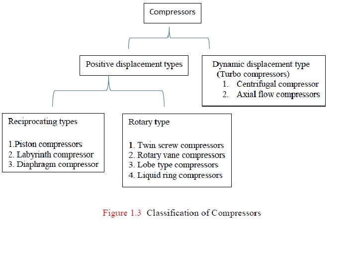
Compressors can be classified in the following different ways. (a)Based on principle of operation: (i) Positive displacement compressor. (ii) Non-positive displacement compressors.

Positive displacement compressors can be further classified based on the type of mechanism used for compression. These can be (i) Reciprocating type positive displacement compressors (ii) Rotary type positive displacement compressors. Rotary compressors of this type are available in the names as given below; (i) Roots blower (ii) Vane type compressors

RECIPROCATING COMPRESSORS 1. PISTON COMPRESSORS A. SINGLE CYLINDER COMPRESSOR
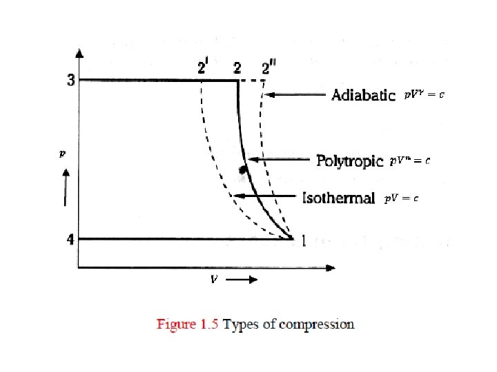

Isothermal compression: Compression of air takes place at constant temperature Adiabatic compression: There is no flow of heat energy into or out of the gas during expansion or compression.

Polytrophic compression: This process lies between Isothermal and adiabatic. In pneumatics, most compression/expansions are neither adiabatic (Very fast) nor isothermal (Very slow). Efficiency of compressor : In a reciprocating compressor the work is minimum when compression follows the isothermal process. The ratio of isothermal work done to the actual work done is called isothermal efficiency.

WORK DONE IN A SINGLE STAGE COMPRESSOR CONSIDERING CLEARANCE.

Volumetric efficiency

Control of compressors Continuous capacity regulation: • This method involves continuous control of drive motor or valve according to variation in pressure. • The result is normally a small pressure variations (0. 1 to 0. 5 bar), depending on the regulation system‟s amplification and its speed.

Load/unload regulation: • This method involves the acceptance of variation in pressure between two values • This takes place by completely stopping the flow at the higher pressure (off loading) and resume the flow rate (loading) when the pressure has dropped to the lowest valve. • Pressure variation depend on the permitted number of load/unload cycles per time unit, but normally lie within the range of 0. 3 to 1 bar.
 Start/Stop and Load/unload controls 1. The simplest control")
Regulation principles for displacement compressors a) Start/Stop and Load/unload controls 1. The simplest control mechanism turns the compressor on or off in response to system pressure 2. When the present system high pressure is reached, the compressed is turned off. When the system pressure falls to the preset minimum, the compressor is turned on. 3. Compressors less than 5 -10 k. W are often controlled by completely stopping the electric motor when the pressure reaches an upper limit valve and restarting it when the pressure passes the lower limit value. 4. This is an effective regulation method under the condition that the number of starts per time unit is kept low.
 Pressure Relief valve This valve releases excess pressure into the atmosphere when the")
b) Pressure Relief valve This valve releases excess pressure into the atmosphere when the preset pressure is reached. The preset pressure can be set by adjusting the spring tension of the spring. Now
By pass regulation In this method, pressure relieved air is cooled and returned to")
c)By pass regulation In this method, pressure relieved air is cooled and returned to the compressor intake. This method is often used on process compressors where gas is unsuitable or too valuable to release into the atmosphere.
 Throttling the intake 1. Throttling is an easy method to reduce the flow.")
d) Throttling the intake 1. Throttling is an easy method to reduce the flow. 2. By increasing the pressure ratio across the compressor, depending on the induced under pressure in the intake, the method is however limited to a small regulation range. 3. Liquid injected compressors, which have a large permitted pressure ratio, can however be regulated down to 10 % of the maximum capacity. This method makes relatively high energy demands, due to the high pressure ratio.
 Pressure relief with throttled intake. 1. The most common regulation method currently used")
e) Pressure relief with throttled intake. 1. The most common regulation method currently used that unites a maximum regulation range(0 -100%) with low energy consumption, only 15 -20% of full load power with an off-loaded compressor (zero flow). 2. The intake valve is closed, but with a small opening remaining, at the same time as a blow off valve opens and relieves the outgoing air from the compressor
 Speed regulation A combustion engine, turbine or frequency controlled electric motor controls the")
f) Speed regulation A combustion engine, turbine or frequency controlled electric motor controls the compressor‟s speed and thereby the flow. It is an efficient method to attain an equal outgoing pressure and low energy consumption.

CONDITIONING AND DISTRIBUTION OF COMPRESSED AIR : The purpose of the fluid conditioners is to make the compressed air more acceptable and suitable fluid medium for the pneumatic system as well as the operating personal. The following five fluid conditioners are used in pneumatic systems 1. Air Filters 2. Air Regulators 3. Air Lubricator

AIR FILTERS: The purpose of the air filter is to clean the compressed air of all impurities and any condensate it contains. Function of air filters: 1. To remove all foreign matter and allow dry and clean air flow without restriction to regulator and then to the lubricator 2. To condensate and remove water from the air 3. To arrest fine particles and all solid contaminants from air

Source of contamination. 1. The quality of air being drawn into the compressor 2. The type and operation of the air compressor 3. Compressed air storage devices and distribution systems

Factor affecting selection of filters 1. Size of particles to be filtered from the system 2. Capacity of the filter 3. Accessibility and maintainability 4. Life of the filter 5. Ability to drain the condensate

Construction of typical cartridge type filter:

AIR REGULATOR: Function: The function of the air pressure regulator is to maintain working pressure virtually constant regardless of fluctuations of the line pressure and air consumption. When the pressure is too low, it results in poor efficiencies and when the pressure is too high, energy is wasted and equipment’s performance decay faster. Generally pressure is regulated in pneumatic system at two places. 1. At the receiver tank 2. In the load circuits

Types of Pressure regulator 1. Diaphragm type regulator 2. Piston type regulator 1. Diaphragm type regulator is commonly used in Industrial pneumatic system. There are two types of diaphragm type regulator i) Non- reliving or non-venting type. ii) Relieving or venting type

Relieving or Venting Type Pressure regulator

Non-Relieving or Non-Venting Type Pressure regulator

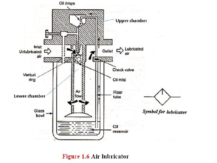
AIR LUBRICATOR: Function: The function of air lubricator is to add a controlled amount of oil with air to ensure proper lubrication of internal moving parts of pneumatic components. Lubricants are used to 1. To reduce the wear of the moving parts 2. Reduce the frictional losses 3. Protect the equipment form corrosion Excessive lubrication is undesirable. Excessive lubrication may results in 1. malfunctioning of components, 2. seizing and sticking of components after prolonged downtime 3. environmental pollution
 /Service Unit")
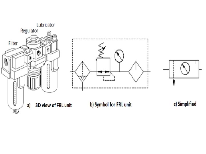
Filter Regulator Lubricator Unit (FRL Unit) /Service Unit

PNEUMATICS ACTUATORS: 1. Pneumatic actuators are the devices used for converting pressure energy of compressed air into the mechanical energy to perform useful work. 2. Actuators are used to perform the task of exerting the required force at the end of the stroke or used to create displacement by the movement of the piston. 3. The pressurised air from the compressor is supplied to reservoir. 4. The pressurised air from storage is supplied to pneumatic actuator to do work.

TYPES OF PNEUMATICS ACTUATORS 1. Linear Actuator or Pneumatic cylinders 2. Rotary Actuator or Air motors 3. Limited angle Actuators

Types of Pneumatic cylinders /Linear actuators The different classification scheme of the pneumatic cylinders are given below 1. Based on application for which air cylinders are used i) Light duty air cylinders ii) Medium duty air cylinders iii) Heavy duty air cylinders
 Single acting cylinder ii) Double acting cylinder")
2. Based on the cylinder action i) Single acting cylinder ii) Double acting cylinder a. Single rod type double acting cylinder b. Double rod type double acting cylinder
 Rotating type air cylinder ii) Non rotating type")
3. Based on cylinder’s movement i) Rotating type air cylinder ii) Non rotating type air cylinder 4. Based on the cylinder’s design 1. Telescopic cylinder 2. Tandem cylinder 3. Rod less cylinder I. Cable cylinder, II. Sealing band Cylinder with slotted cylinder barrel III. Cylinder with Magnetically Coupled Slide 4. Impact cylinder 5. Duplex cylinders 6. Cylinders with sensors
 Single acting cylinders.")
Based on the cylinder action A) Single acting cylinders.

There are varying designs of single acting cylinders including: 1. Diaphragm cylinder 2. Rolling diaphragm cylinder 3. Gravity return single acting cylinder 4. Spring return single acting cylinder

Diaphragm cylinder: piston is replaced by a diaphragm of hard rubber, plastic or metal clamped between the two halves of a metal casing expanded to form a wide, flat enclosure

Rolling diaphragm cylinder : They are similar to diaphragm cylinders. They too contain a diaphragm instead of piston, which is this instance rolls out along the inner walls of the cylinder when air pressure is applied to the device, thereby causing the operating stem to move outwards. Compared with the standard diaphragm type, a rolling diaphragm cylinder is capable of executing appreciably longer operating strokes (averaging from 50 mm to 800 mm).

Gravity Return Single Acting Cylinder

Spring Return Single Acting Cylinder

Double acting cylinders.

Telescopic Cylinder

Cable cylinder: • It is used for very long strokes, up to 2000 mm. • It consists of nylon jacketed cable which enters the cylinder barrel and is attached to one end of internal cylinder and exits through the gland seal and enters into the other end of the internal cylinder through the another gland seal. • When compressed air enters the cylinder the piston moves from endto-end.

Cylinder with Magnetically Coupled Slide The magnetic cylinders are available upto the size of about 40 mm diameter and stroke lengths from 50 mm to 4000 mm. They can operate at the speed of about 3000 mm/sec. The major advantages of this type of cylinders are i) There is no leakage ii) There is no direct contact of moving elements therefore the wear is less iii) The orientation of the carriage can be changed easily,

Position sensor for cylinders

Cylinder mountings.

VALVES 1. Direction control valve 2. Non return valves 3. Flow control valves 4. Pressure control valves
 Poppet or seat valves - Ball")
DIRECTION CONTROL VALVES 1. Based on construction i) Poppet or seat valves - Ball seat valve - Disc seat valve - Diaphragm Valves ii) Sliding spool valves - Longitudinal slide valve -Suspended spool valves -- Rotary spool valves 2. Based on the Number of ports i) Two way valves ii) Three way valves iii) Four way valves
 Mechanical ii) Electrical iii) Pneumatic 4. Based")
3. Based on methods of actuation i) Mechanical ii) Electrical iii) Pneumatic 4. Based on Size of the port 5. Based on mounting styles i) Sub base ii) Manifold iii) In-line iv) Valve island

POPPET DIRECTION CONTROL VALVES A. Ball seat valve. (a simple 2/2 normally closed valve. )
")
B. Disc seat poppet valve(disc type 3/2 way DCV )


- Slides: 66