UNIT 3 Parallel Port Interfacing Interfacing of 8051


 Sin(Ɵ) Count= 2. 5+(2. 5×sinƟ) Count× 256/5")


 §")
")


- Slides: 49
UNIT 3 Parallel Port Interfacing
Interfacing of 8051 with DAC 0808
Interfacing
Program To Generate Triangular Wave ORG 0000 H MOV A, #00 H RISE: MOV P 1, A INC A CJNE A, #0 FFH, RISE FALL: MOV P 1, A DEC A CJNE A, #00 H, FALL SJMP RISE END
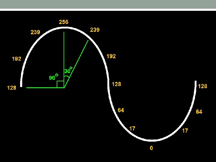
Sine Wave Generation Angle in Degrees (Ɵ) Sin(Ɵ) Count= 2. 5+(2. 5×sinƟ) Count× 256/5 0 0 2. 5 128 30 0. 500 3. 75 192 60 0. 866 4. 66 239 90 0. 999 4. 99 256 120 0. 865 4. 66 239 150 0. 499 3. 74 192 180 0. 001 2. 49 128 210 0. 501 1. 24 64 240 0. 866 0. 33 17 270 0. 999 0. 002 0 300 -0. 864 0. 337 17 330 0. 497 1. 255 64 360 0. 0025 2. 506 128
Program To Generate Sine wave ORG 0000 H MOV R 0, #30 H ; Starting Address ; Store the Calculated Values on address from 30 H MOV @R 0, #128 INC R 0 MOV @R 0, #192 INC R 0 MOV @R 0, #239 INC R 0 MOV @R 0, #256 INC R 0
MOV @R 0, #239 INC R 0 MOV @R 0, #192 INC R 0 MOV @R 0, #128 INC R 0 MOV @R 0, #64 INC R 0 MOV @R 0, #17 INC R 0 MOV @R 0, #0 INC R 0 MOV @R 0, #17 INC R 0 MOV @R 0, #64
MOV R 0, #30 H HERE: MOV P 1, @R 0 INC RO CJNE R 0, #3 CH, HERE MOV R 0, #30 H SJMP HERE END
Interfacing of Stepper Motor with 8051
Stepper Motor Structure
Full-Stepper Motor Step Coil 1 Coil 2 Coil 3 Coil 4 1 I I 0 0 0 CH 2 0 I I 0 06 H 3 0 0 I I 03 H 4 I 0 0 I 09 H
Half-Stepper Motor
Half-Stepper Motor Step Coil 1 Coil 2 Coil 3 Coil 4 Hex 1 I 0 08 H 2 I I 0 0 0 CH 3 0 I 0 0 04 H 4 0 I I 0 06 H 5 0 0 I 0 02 H 6 0 0 I I 03 H 7 0 0 0 I 01 H 8 I 0 0 I 09 H
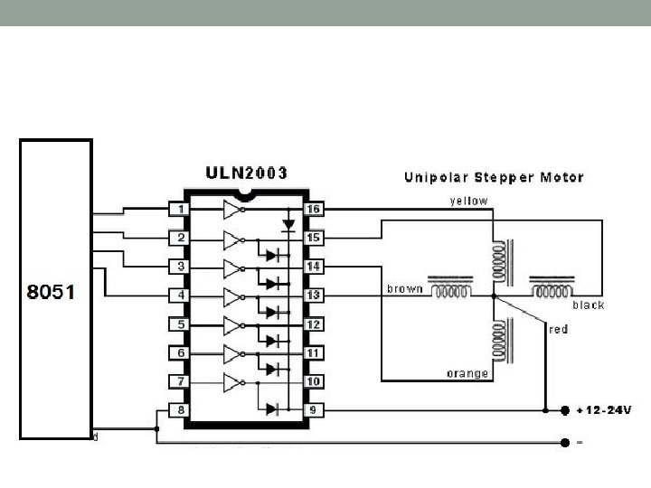
Interfacing
ULN 2003 Driver IC
Write a Program to rotate a motor 117 o in clockwise direction. The motor has step angle of 1. 80 •
ORG 0000 H MOV R 0, #30 H ; Starting Address ; Store the Calculated Values on address from 30 H MOV @R 0, #0 CH INC R 0 MOV @R 0, #06 H INC R 0 MOV @R 0, #03 H INC R 0 MOV @R 0, #09 H
MOV R 0, #30 H MOV R 1, #65 HERE: MOV P 1, @R 0 INC RO DJNZ R 1, NXT SJMP LAST NXT: CJNE R 0, #33 H, HERE MOV R 0, #30 H SJMP HERE LAST: END
Interfacing of Motion Detectors with 8051 Motion Detector Sensors: § Passive Infrared (PIR) § Mirco. Wave (MW) § Area Reflective Type(IR) § Ultrasonic § Vibration
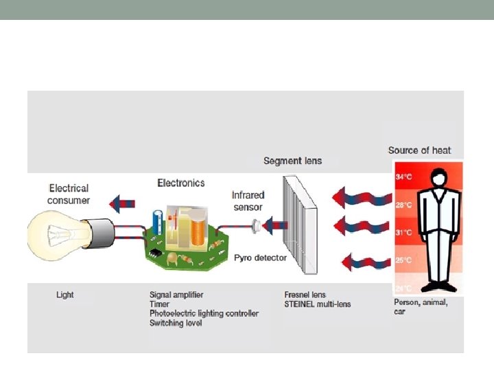
Passive Infra. Red Sensor(PIR)
Working Principle
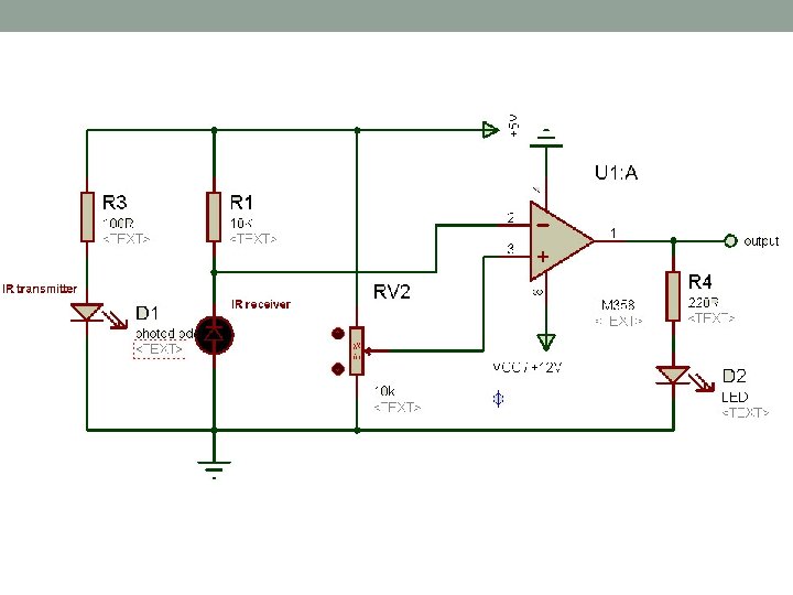
Infra. Red Sensor
Ultrasonic Sensor
Working Principle
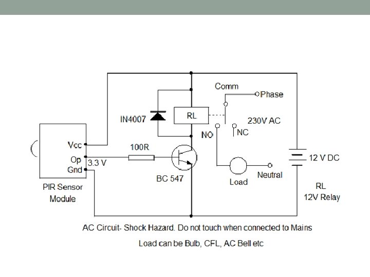
Interfacing of PIR sensor with 8051
PIR EQU P 2. 4 LED EQU P 2. 3 ORG 0000 H L 1: JNB PIR, L 1 SETB LED L 2: JB PIR, L 2 CLR LED SJMP L 1 END
Interfacing of LM 35 with 8051
Interfacing of LCD and LM 35 with 8051 via ADC 0808
SEL_A EQU P 3. 1 SEL_B EQU P 3. 2 SEL_C EQU P 3. 3 ALE EQU P 3. 4 START EQU P 3. 5 EOC EQU P 3. 6 OE EQU P 3. 7 ADC_DATA EQU P 1 RS EQU P 2. 0 RW EQU P 2. 1 EN EQU P 2. 2 _ | > | | / ADC _ | > _| LCD
ORG 0000 H MOV A, #02 H ACALL CMD MOV A, #01 H ACALL CMD MOV A, #38 H ACALL CMD MOV A, #06 H ACALL CMD MOV A, #0 EH ACALL CMD MOV A, #80 H ACALL CMD
MOV ADC_DATA, #0 FFH SETB EOC CLR ALE CLR OE CLR START ; DATA PORT TO INPUT ; EOC AS INPUT ; REST OF OUTPUT SIGNALS MAIN: MOV A, #80 H ACALL CMD SETB SEL_A CLR SEL_B CLR SEL_C SETB ALE SETB START ; SELECT ANALOG CHANNEL 1 ; LATCH CHANNEL SELECT ; START CONVERSION
CLR ALE CLR START HERE: JB EOC, HERE ; WAIT FOR END OF CONVERSION HERE 1: JNB EOC, HERE 1 SETB OE MOV A, ADC_DATA CLR OE ; ASSERT READ SIGNAL ; READ DATA ; ADC DATA IS NOW IN ACCUMULATOR ; START OVER FOR NEXT CONVERSION
MOV B, #256 DIV A, B MOV B, #50 MUL AB MOV B, #10 MUL AB
MOV R 1, A ANL A, #11110000 SWAP A MOV B, #30 H ADD A, B ACALL DISP MOV A, R 1 ANL A, #00001111 MOV B, #30 H ADD A, B ACALL DISP
MOV A, #83 H ACALL CMD MOV A, #"C" ACALL DISP SJMP MAIN
CMD: ACALL INIT MOV P 0, A CLR RS CLR RW SETB EN CALL DELAY CLR EN RET DISP: ACALL INIT MOV P 0, A SETB RS CLR RW SETB EN ACALL DELAY CLR EN RET
; POLLING FUNCTION INIT: CLR EN CLR RS MOV P 1, #0 FFH SETB RW L 1: SETB EN JB P 1. 7, L 1 CLR EN DELAY: MOV R 3, #10 L 1: MOV R 4, #250 L 2: DJNZ R 4, L 2 DJNZ R 3, L 1 RET END
Frequency Counter using 8051
Frequency Counter using 8051
Data Acquisition System
Sensors Sensor Phenomenon Thermocouple, RTD, Thermistor Temperature Photo Sensor Light Microphone Sound Strain Gage, Force and Pressure Piezoelectric Transducer Potentiometer, LVDT, Optical Encoder Position and Displacement Accelerometer Acceleration p. H Electrode p. H
Signal Conditioning • Amplification • Excitation • Linearization • Cold-Junction Compensation • Filtering • Isolation • High Impedance • RMS Signal Conditioning
Example of DAS
Optocoupler