Unit 3 Optoelectronics Devices 7 1 Optoelectronic Devices


 A 1 foot-candle =")


: Noise Equivalent Power (NEP):")


: Intro. : • Liquid crystals exhibit the property")

 Display Colour monitors have multiple Intro. : (RGB)")

 Digital Light Processing")

- Slides: 39
Unit 3 Optoelectronics Devices
7. 1 Optoelectronic Devices: Introduction: Optoelectronics is the field that deals with the study of devices that emit, detect and control light in the wavelength spectrum from ultraviolet to infrared.
Radiometry: Study of properties and characteristics of electromagnetic radiation.
Photometry: Science that deals with visible light and its perception by human vision.
Flux: Flow phenomenon OR a field condition occurring in space. Types that we study: 1. Radiometric flux = ΦR in watts (W) 2. Photometric flux = ΦP in lumens (lm)
Lumen & Watts relation: Lumen is defined as amount of photometric flux generated by 1/683 watt of radiometric flux at 555 nanometer (wavelength – λ) where the vision sensitivity of human eye is maximum.
Efficacy: ΦP K = ------- lm / W ΦR
Intensity: Describes the flux distribution in space.
Radiometric Intensity: Radiometric flux density per steradian. i. e. , ΦR IR = --------- W / sr Ω
Radiant Incidence, EP ΦR = -------- W / m 2 A
Illumination, ΦP EP = -------- lm / m 2 (lux) A 1 foot-candle = 10. 764 lux
7. 2 Classification:
7. 2 Photosensors: Detect the presence of light energy ------Thermal Sensors: absorb radiation (lght energy) and react to the resulting temperature rise of the device.
Characteristic Parameters: 1. 2. 3. 4. 5. 6. Responsivity (R): Noise Equivalent Power (NEP): Detectivity and Dec-Star: Quantum Efficiency: Response Time: Sensor Noise:
7. 3 Photoconductors: • Also called photoresistors • Devices whose resistance increases or decreses with increasing incident light intensity. • Resistance-illuminance relation is given by: R-resistance, E-illuminance in lux / foot candle
Cross section of photoconductor: When light is incident on the photoconductor, electrons jump from V band to C band, hence the R of device decreases.
7. 4 Photodiodes: • Photodiodes generate V or I, when PN junction illuminated by light. • Constructed using – Si, Ge, In. Ga. As, Pb. S, Hg. Cd. Te. • Types: – PN photodiodes – PIN photodiode – Schottky photodiode – Avalanche photodiode
Cross-section of PN photodiode: Working: When light with sufficient energy strikes the diode, photo induced carriers are generated which include electrons in C band I n N-type and holes in P-type semiconductor, generating potential difference between the terminals
V-I characteristics of a photodiode:
Application circuits of photodiodes: 1. Photovoltaic mode: 2. Photoconductive mode:
Solar cells: • The operation of solar cell is based on photovoltaic effect • Light energy converted to electric energy, in a pn junction, in photovoltaic mode • Special arrangement is made so that maximum light falls on junction
• Some of the light energy causes recombination which makes possible electrons to flow through RL constituting current.
7. 5 Phototransistors: • Base is not used • Radiation is concentrated on CB junction, behaves as base drive. • No radiation: • With radiation:
Characteristics & Symbol:
Application Circuits:
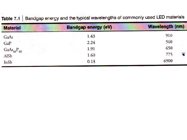
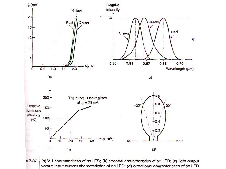
7. 10 Light Emitting Diodes: • • Emit light when FB Popular optoelectronic source Less power consumption Less expensive Working principle • In the process of recombination energy radiated in the form of heat & light • Ga. As & Ga. As. P emit m uch photons
pn junction of LED:
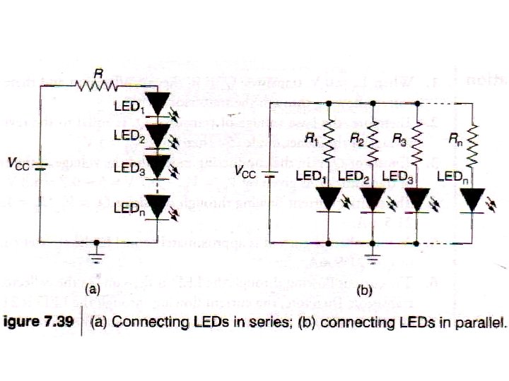
Application Circuits:
7. 11 Liquid Crystal Display (LCD): Intro. : • Liquid crystals exhibit the property of both solid as well as liquid (intermediate phase of matter) Key point: When voltage is applied to LC they do not pass light, that is they become opaque
Construction of LCD: Working: • Electrodes are shaped as required alpha-numerals / symbols • Polarizers (front & back) are arranged to control light flow. • No voltage to that segment, crystal molecules straighten, pass the light, nothing visible • Voltage applied to the segment, crystal molecules not straighten, do not pass the light, and that character is visible
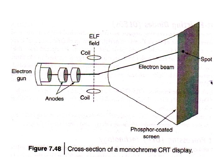
7. 12 Cathod Ray Tube (CRT) Display Colour monitors have multiple Intro. : (RGB) electron guns • It is a vacuum tube • Electron gun emits a beam, creating a spot of light on fluorescent screen. • The beam is controlled by deflecting coils, making possible the movement of beam in turn the spot. • Horizontal and vertical scanning / movement of beam produce image • The motion effect is observed due eye’s persistence nature as fluorescence retains the light on screen for that much period.
Advantages & disadvantages: • High resolution • High luminance • Viewing angle, almost 180° • • Bulky More power required High voltage to operate Fatigue to eyes
7. 13 Emerging display technologies: • • • OLED (organic LED) Digital Light Processing (DLP) Technology Plasma Display Panels (PDP) Field Emission Displays (FED) Electronic Ink Displays (EID)
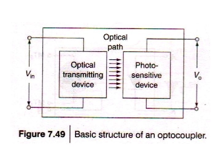
7. 14 Opto-couplers: Defn. Optocoupler / isolaor is a device that uses a short optical transmission path to transfer signals between the elements of a circuit. Isolates 2 circuits electrically