Unit 3 InputOutput system InputOutput Problems IO operations

Unit 3 Input/Output system

Input/Output Problems I/O operations means data transfer between I/O device and cpu/memory Wide variety of peripherals (I/O devices) Delivering different amounts of data At different speeds In different data formats and word length All slower than CPU and RAM So to overcome all these difficulties it is necessary to use a module in between system bus and peripherals called I/O module or I/O system Need I/O modules w/ some “intelligence”

I/O SYSTEM Computer system I/o architecture is it interface to the Outside world. Interface to CPU and Memory Interface to one or more peripherals Architecture provide systematic way of controlling interaction with the outside world and provide OS with the information it needs to manage I/O activity effectively
 human being easily interact with machine")
What are external devices? Human readable (human interface) human being easily interact with machine Monitor, printer, keyboard, mouse Machine readable : suitable for communication with external hardware. Disk, tape, sensors Communication : devices suitable for communication with remote devices Modem Network Interface Card (NIC)

What are external devices? Three categories: Human readable Machine readable Communication External Devices

External device contains control logic, buffer, transducer or converter. Control logic controls the operation of an external device. In response external device sends some status signal. Like BUSY, Ready etc Transducer converts data from electrical to other forms

I/O Module Function Control & Timing: CPU Communication Device Communication: I/O module must perform device communication which involves commands, status information and data Data Buffering: needed because the data rate transfer of I/O devices is higher than cpu and memory so data is stored in buffer Error Detection: and reporting errors to cpu like bad disk tracks, transmission errors etc
 I/O module device status I/O module returns status If")
I/O Steps CPU checks (interrogates) I/O module device status I/O module returns status If ready, CPU requests data transfer by sending a command to the I/O module gets a unit of data (byte, word, etc. ) from device I/O module transfers data to CPU Variations of these steps for output, DMA, etc.

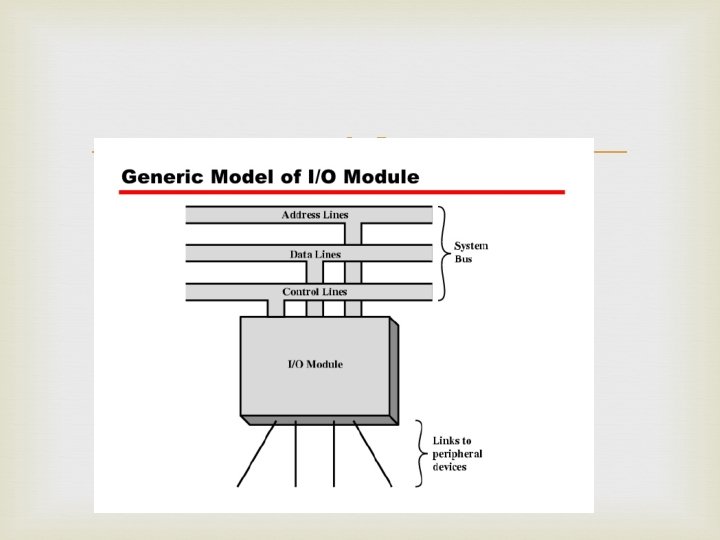
I/O Module Diagram
")
Input Output Techniques Programmed I/O Interrupt driven I/O Direct Memory Access (DMA)

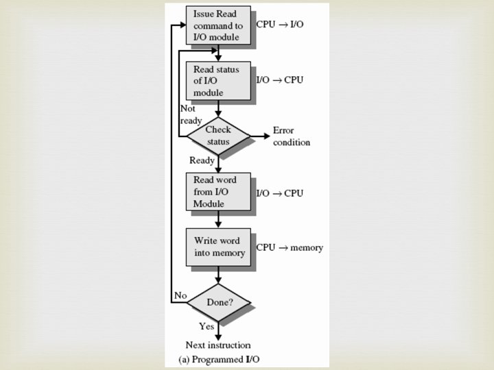
Programmed I/O operations means data transfer between I/O device and cpu/memory If in any computer system I/O operations are completely controlled by the processor then that system is said to be using ‘Programmed I/O’ Here CPU will execute programs that Initiates Directs and Terminates the I/O operations like sensing device status , sending a R/W command transferring the data.

Programmed I/O The CPU issues a command then waits for I/O operations to be complete. As the CPU is faster than the I/O module, the problem with programmed I/O is that the CPU has to wait a long time for the I/O module of concern to be ready for either reception or transmission of data. The CPU, while waiting, must repeatedly check the status of the I/O module, and this process is known as Polling. As a result, the level of the performance of the entire system is severely degraded.

Programmed I/O basically works in these ways: -CPU requests I/O operation -I/O module performs operation -I/O module sets status bits -CPU checks status bits periodically -I/O module does not inform CPU directly -I/O module does not interrupt CPU -CPU may wait or come back later

I/O commands types Control : to activate peripheral and tell them what to do Test : used to test various status conditions associated with I/O module Read : read data from peripherals Write : transfer data to peripheral

I/O interfacing tech. i/o devices can be interfaced to computer system in two ways. Memory mapped I/O Memory address space I/O address space Total address space

Memory mapped I/O Memory and I/O share the entire address range of processor Memory control signals are used to read and write I/O operations. MEWR , MERD Data transfer is between register and I/O devices

I/O mapped I/o processor provides separate address range for memory and I/O devices. I/O control signals are used to control read and write operations IOR /IOW Data transfer is between accumulator and I/O device IN and OUT instruction IN AL, 05 H (IN AL, PORT address) OUT 05 H, AL (05 H port address)

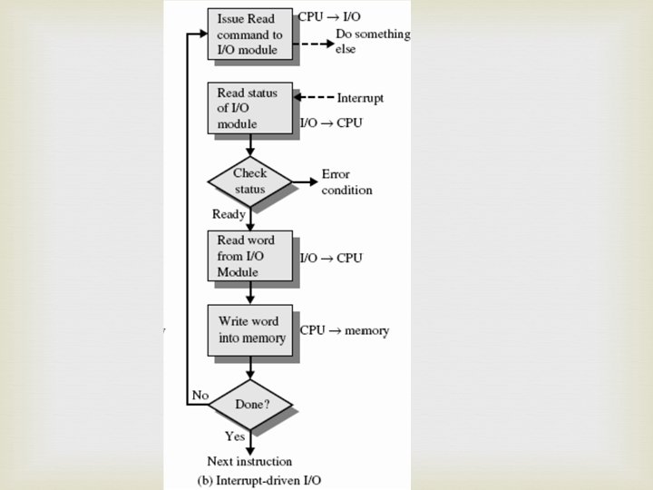
Interrupt Driven I/O Basic Operation CPU issues read command I/O module gets data from peripheral whilst CPU does other work I/O module interrupts CPU requests data I/O module transfers data

Interrupt Driven I/O The CPU issues commands to the I/O module then proceeds with its normal work until interrupted by I/O device on completion of its work. For input, the device interrupts the CPU when new data has arrived and is ready to be retrieved by the system processor. For output, the device delivers an interrupt either when it is ready to accept new data or to acknowledge a successful data transfer. Although Interrupt relieves the CPU of having to wait for the devices, but it is still inefficient in data transfer of large amount because the CPU has to transfer the data word by word between I/O module and memory

Below are the basic operations of Interrupt: 1. -CPU issues read command 2. -I/O module gets data from peripheral whilst -CPU does other work 3. -I/O module interrupts CPU 4. -CPU requests data 5. -I/O module transfers data

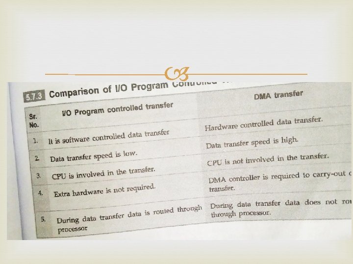
Direct Memory Access Interrupt driven and programmed I/O require active CPU intervention Transfer rate is limited CPU is tied up DMA is the answer
 means CPU grants I/O module authority to read from")
DMA Direct Memory Access (DMA) means CPU grants I/O module authority to read from or write to memory without involvement. DMA module controls exchange of data between main memory and the I/O device. Because of DMA device can transfer data directly to and from memory, rather than using the CPU as an intermediary, and can thus relieve congestion on the bus. CPU is only involved at the beginning and end of the transfer and interrupted only after entire block has been transferred.
 that manages")
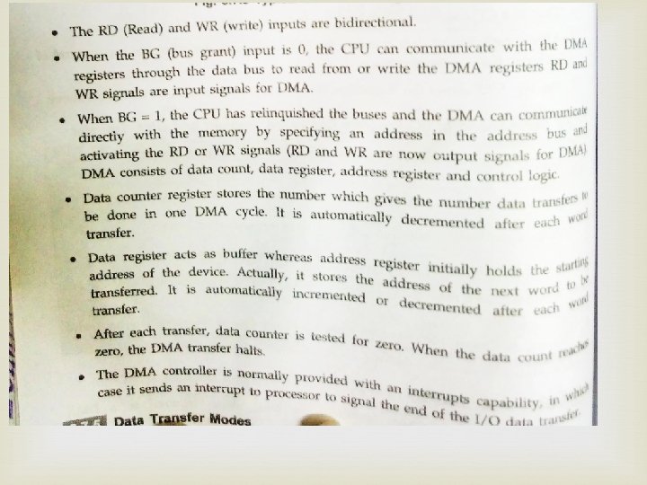
Direct Memory Access needs a special hardware called DMA controller (DMAC) that manages the data transfers and arbitrates access to the system bus. DMA increases system concurrency by allowing the CPU to perform tasks while the DMA system transfers data via the system and memory busses Hardware design is complicated because the DMA controller must be integrated into the system, and the system must allow the DMA controller to be a bus master.
 on bus DMA controller takes over from CPU for")
DMA Function Additional Module (hardware) on bus DMA controller takes over from CPU for I/O

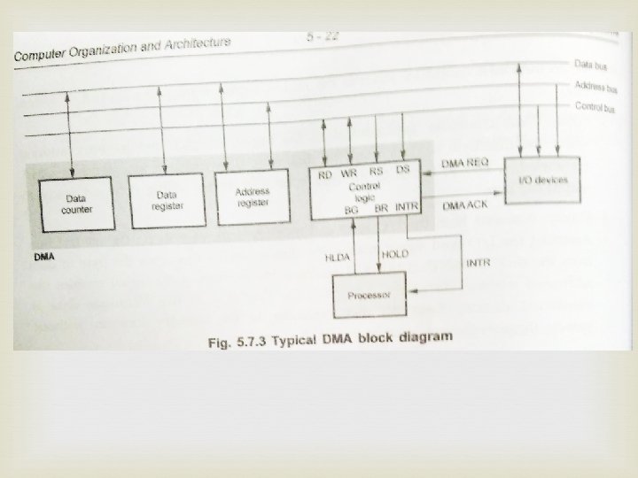
Typical DMA Module Diagram

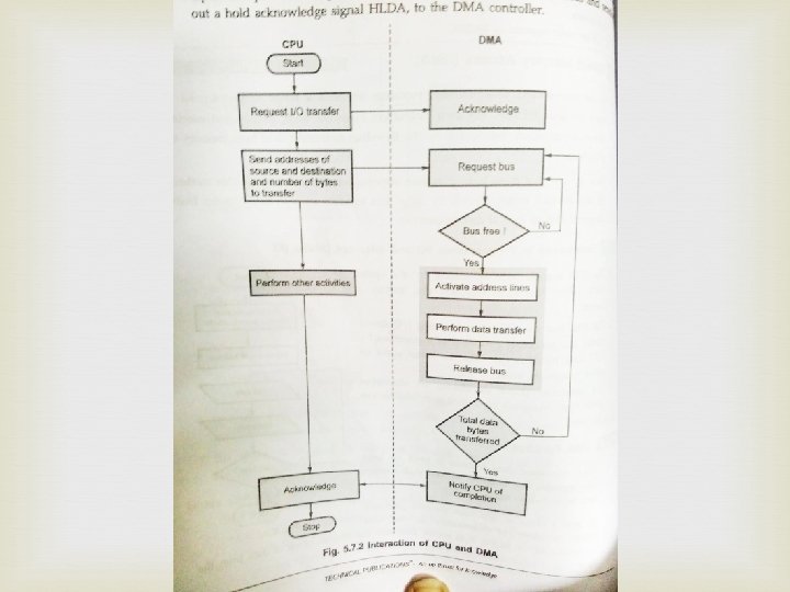
DMA Operation CPU tells DMA controller: Read/Write Device address Starting address of memory block for data Amount of data to be transferred CPU carries on with other work DMA controller deals with transfer DMA controller sends interrupt when finished
 Block transfer mode Demand transfer mode")
Data transfer modes Single transfer mode(cycle stealing) Block transfer mode Demand transfer mode
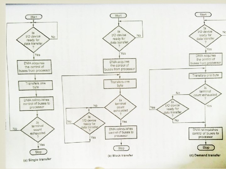

DMA Transfer Cycle Stealing single transfer mode DMA controller takes over bus for a cycle Transfer of one word of data Not an interrupt CPU does not switch context CPU suspended just before it accesses bus i. e. before an operand or data fetch or a data write Slows down CPU but not as much as CPU doing transfer

Three Techniques for Input of a Block of Data

82 C 59 A Interrupt Controller

INTEL 82 C 59 A INTERRUPT CONTROLLER To allow the 80386 to handle a variety of devices, it is usually configured with and external interrupt arbiter. The 82 C 59 A External devices are connected to the 82 C 59 A which in turn is connected to the 80386 A single 82 C 59 A can handle up to eight modules, if control for more than eight modules is required a cascade arrangement can be used

The 82 C 59 A is responsible for the management of the interrupts The 82 C 59 A is programmable The 80836 determines the priority scheme to be used by setting a control word in the 82 C 59 A Interrupt modes: Fully nested: the interrupt requests are ordered from 0 (IR 0) through 7 (IR 7) Rotating: In some applications a number of interrupts devices are of equal priority. In this mode a device, after being serviced, receives the lowest priority in the group Special mask: this allows the processor to inhibit interrupts from certain devices

Because the 82 C 55 A is programmable via the control register, it can be used to control a variety of simple peripheral devices The keyboard provides 8 bits of input Two of these bits SHIFT and CONTROL have special meaning to the keyboard handing program executing in the processor The display is also linked by an 8 bit data port and again two lines have special meanings to the display.

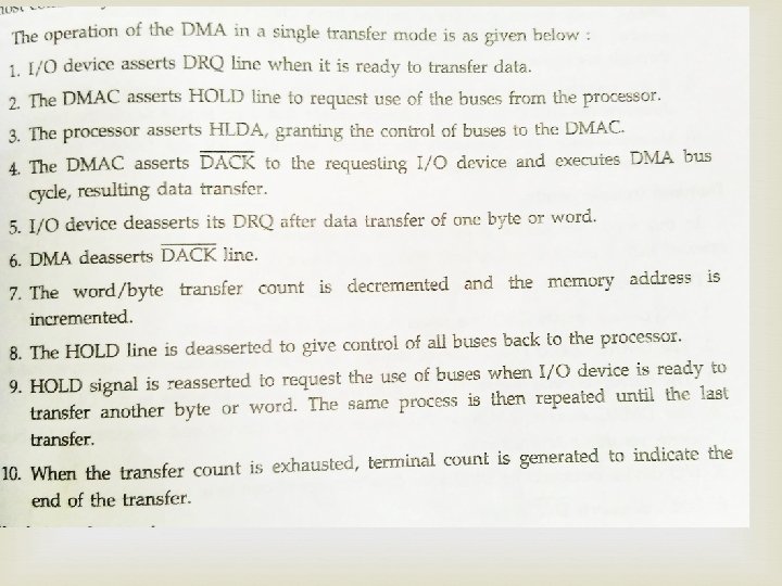
Intel 8237 A DMA Controller Interfaces to 80 x 86 family and DRAM When DMA module needs buses it sends HOLD signal to processor CPU responds HLDA (hold acknowledge) DMA module can use buses E. g. transfer data from memory to disk 1. 2. 3. 4. 5. 6. Device requests service of DMA by pulling DREQ (DMA request) high DMA puts high on HRQ (hold request), CPU finishes present bus cycle (not necessarily present instruction) and puts high on HDLA (hold acknowledge). HOLD remains active for duration of DMA activates DACK (DMA acknowledge), telling device to start transfer DMA starts transfer by putting address of first byte on address bus and activating MEMR; it then activates IOW to write to peripheral. DMA decrements counter and increments address pointer. Repeat until count reaches zero DMA deactivates HRQ, giving bus back to CPU

8237 DMA Usage of Systems Bus
- Slides: 44