Unit 2 Block Diagram Representation By Prof N

Unit 2 Block Diagram Representation By Prof. N V Avhad

Types of Control Systems • Open loop control system • Closed loop control system

Open loop control system • A control system in which the control action is totally independent of output of the system then it is called open loop control system. • Manual control system is also an open loop control system. • The block diagram of open loop control system in which process output is totally independent of controller action.

Practical Examples of Open Loop Control System • Electric Hand Drier • Automatic Washing Machine • Bread Toaster • Automatic Tea/Coffee Maker • Timer Based Clothes Drier • Light Switch • Volume on Stereo System

Open loop control system Advantages of Open Loop Control System • Simple in construction and design. • Economical. • Easy to maintain. • Generally stable. • Convenient to use as output is difficult to measure. Disadvantages of Open Loop Control System • They are inaccurate. • They are unreliable. • Any change in output cannot be corrected automatically

Closed loop control system • Control system in which the output has an effect on the input quantity in such a manner that the input quantity will adjust itself based on the output generated is called closed loop control system.

Closed loop control system Basic element of a closed loop control system • Comparison element • Control element • Correcting element • Process element • Measurement element

Closed loop control system Practical Examples of Closed Loop Control System • Automatic Electric Iron • Servo Voltage Stabilizer • Water Level Controller • Missile Launched and Auto Tracked by Radar • An Air Conditioner • Cooling System in Car

Closed loop control system Advantages of Closed Loop Control System 1. Closed loop control systems are more accurate even in the presence of non-linearity. 2. Highly accurate as any error arising is corrected due to presence of feedback signal. 3. Bandwidth range is large. 4. Facilitates automation. 5. The sensitivity of system may be made small to make system more stable. 6. This system is less affected by noise.

Closed loop control system Disadvantages of Closed Loop Control System 1. They are costlier. 2. They are complicated to design. 3. Required more maintenance. 4. Feedback leads to oscillatory response. 5. Overall gain is reduced due to presence of feedback. 6. Stability is the major problem and more care is needed to design a stable closed loop system.

Comparison of Closed Loop And Open Loop Control System Sr. No. Open loop control system Closed loop control system 1 The feedback element is absent. The feedback element is always present. 2 An error detector is not present. An error detector is always present. 3 It is stable one. It may become unstable. 4 Easy to construct. Complicated construction. 5 It is an economical. It is costly. 6 Having small bandwidth. Having large bandwidth. 7 It is inaccurate. It is accurate. 8 Less maintenance. More maintenance. 9 It is unreliable. It is reliable. 10 Examples: Hand drier, tea maker Examples: Servo voltage stabilizer, perspiration

Transfer function • It is defined as the ratio of the Laplace transform of a output variable to the Laplace transform of a input variable assuming all the initial condition as zero. • In Laplace Transform, if the input is represented by R(s) and output is represented by C(s), then the transfer function will be

Procedure for determining the transfer function of a control system are as follows 1. Form the equations for the system. 2. Take Laplace transform of the system equations, assuming initial conditions as zero. 3. Specify system output and input. 4. Lastly Take the ratio of the Laplace transform of the output and the Laplace transform of the input which is the required transfer function.

Methods of Obtaining a Transfer Function • Block Diagram Method : It is not convenient to derive a complete transfer function for a complex control system. Therefore the transfer function of each element of a control system is represented by a block diagram. Block diagram reduction techniques are applied to obtain the desired transfer function. • Signal Flow Graphs : The modified form of a block diagram is a signal flow graph. Block diagram gives a pictorial representation of a control system. Signal flow graph further shortens the representation of a control system

Block Diagram Representation • Definition – it is pictorial representation of functions performed by each components of a system and that of flow of signals. • The block diagram is obtained after obtaining the differential equation and transfer function of all component • The arrow head pointing toward the block indicates the input and pointing away from the block indicates the output

Block diagram example

Important terms regarding block Diagram

Important terms regarding block Diagram

Important terms regarding block Diagram

Important terms regarding block Diagram

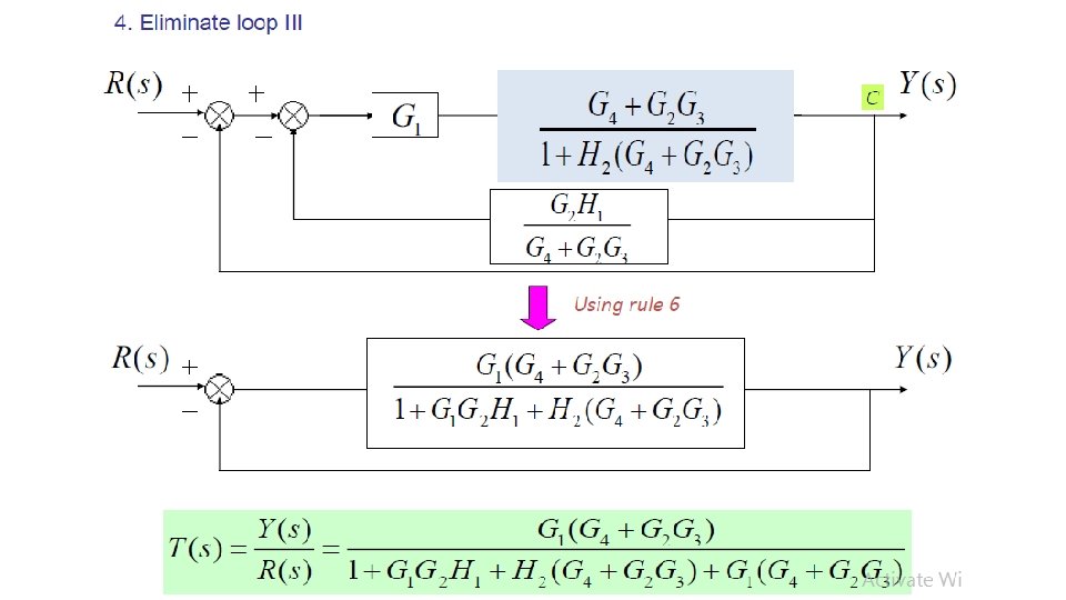
Block diagram reduction technique • The aim of reduction technique is to simplify the block diagram and get transfer function.

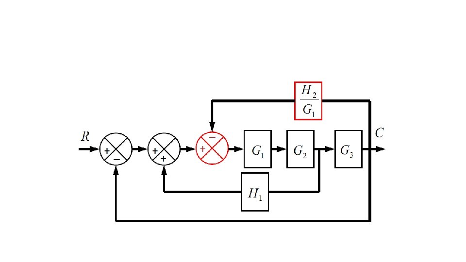
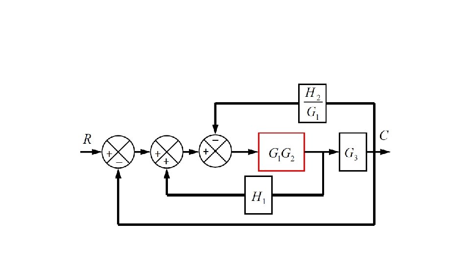
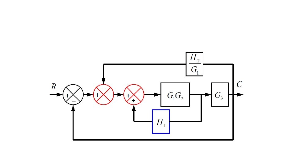
Block diagram reduction technique procedure

Block diagram reduction technique procedure

Block diagram reduction technique procedure

Block diagram reduction technique procedure
 this")
Consider the block diagram shown in the following figure. Let us simplify (reduce) this block diagram using the block diagram reduction rules

Step 1 − Use Rule 1 for blocks G 1 G 1 and G 2 G 2. Use Rule 2 for blocks G 3 G 3 and G 4 G 4. The modified block diagram is shown in the following figure.

Step 2 − Use Rule 3 for blocks G 1 G 2 and H 1 H 1. Use Rule 4 for shifting take-off point after the block G 5 G 5. The modified block diagram is shown in the following figure.
 and G 5")
Step 3 − Use Rule 1 for blocks (G 3+G 4) and G 5 G 5. The modified block diagram is shown in the following figure
G 5 and H")
Step 4 − Use Rule 3 for blocks (G 3+G 4)G 5 and H 3 H 3. The modified block diagram is shown in the following figure.

Step 5 − Use Rule 1 for blocks connected in series. The modified block diagram is shown in the following figure.

Step 6 − Use Rule 3 for blocks connected in feedback loop. The modified block diagram is shown in the following figure. This is the simplified block diagram .

Therefore, the transfer function of the system is

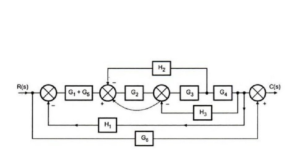
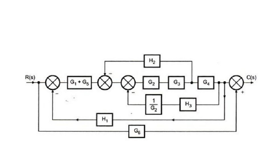
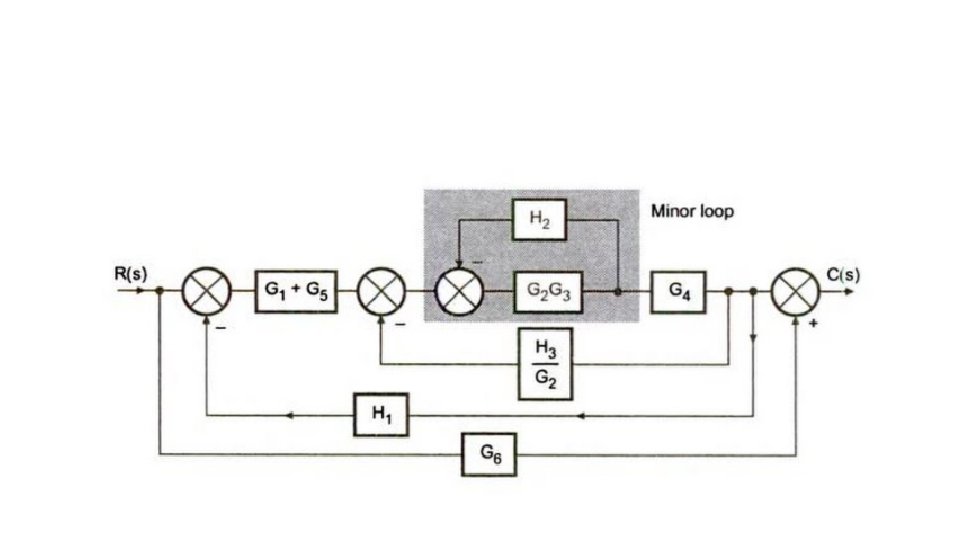
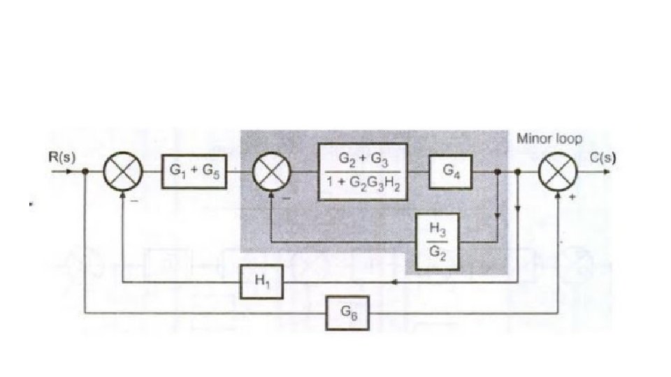
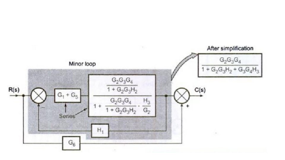
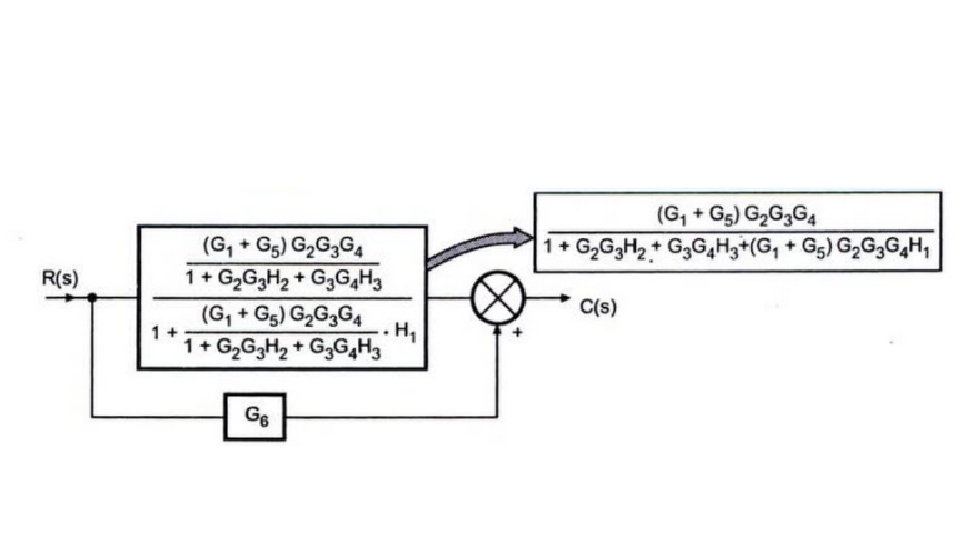
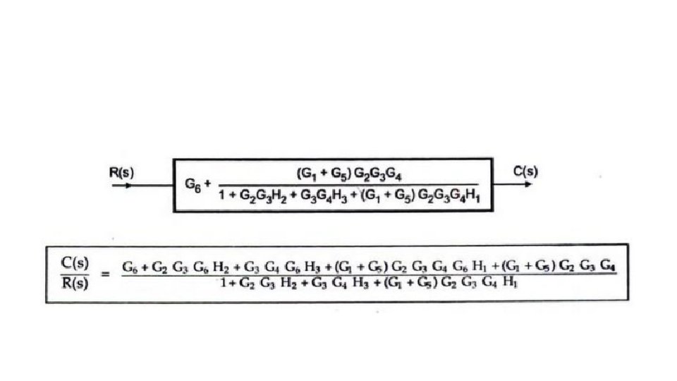
Find the transfer function of the following block diagrams:
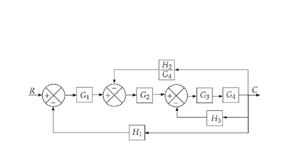
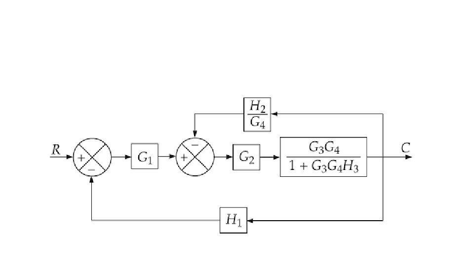
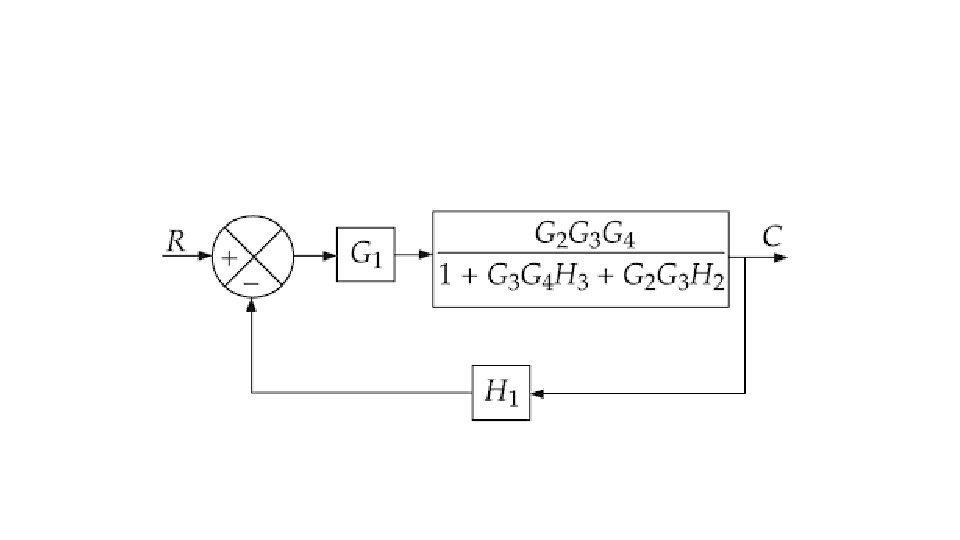
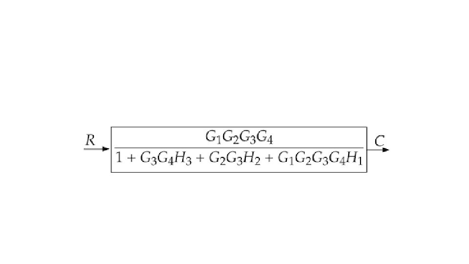

Find the transfer function of the following block diagrams:
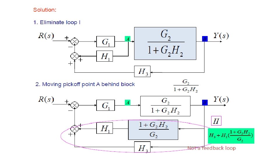
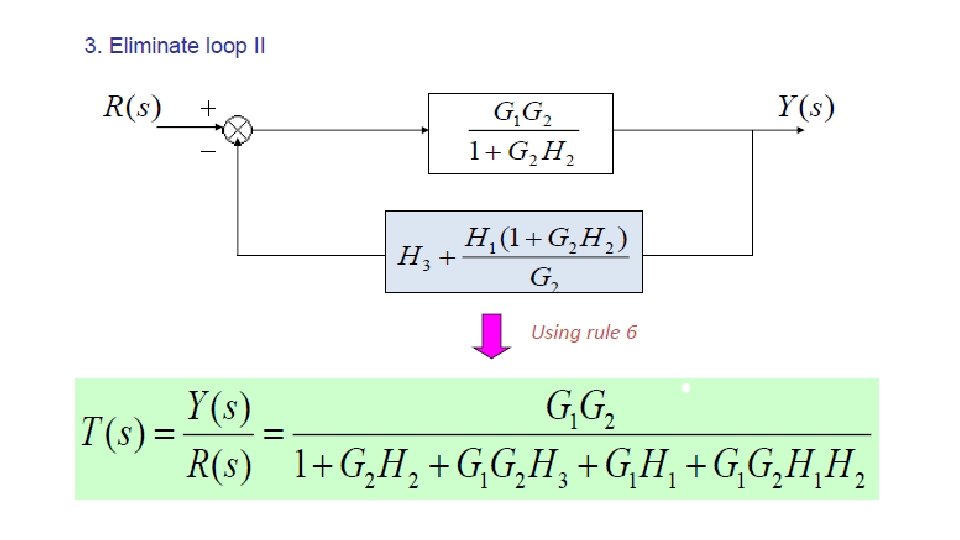

Find the transfer function of the following block diagrams:
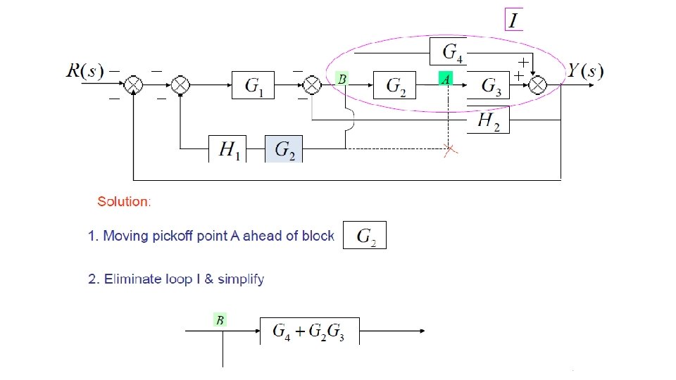
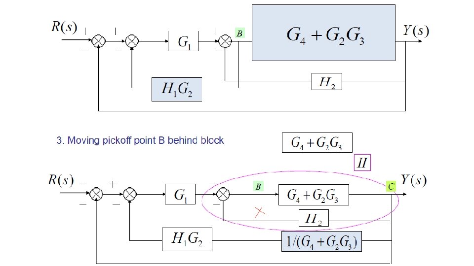

Find the transfer function of the following block diagrams:
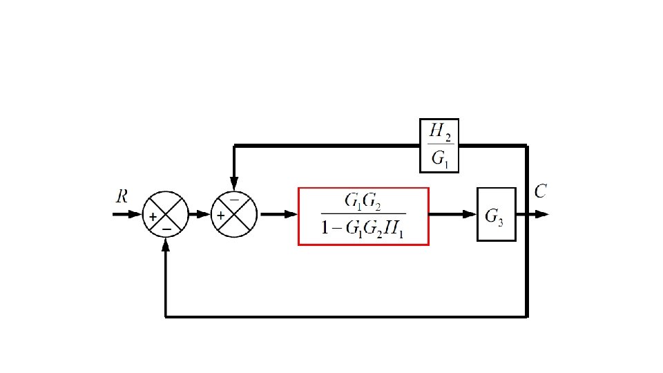
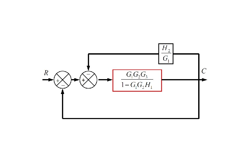
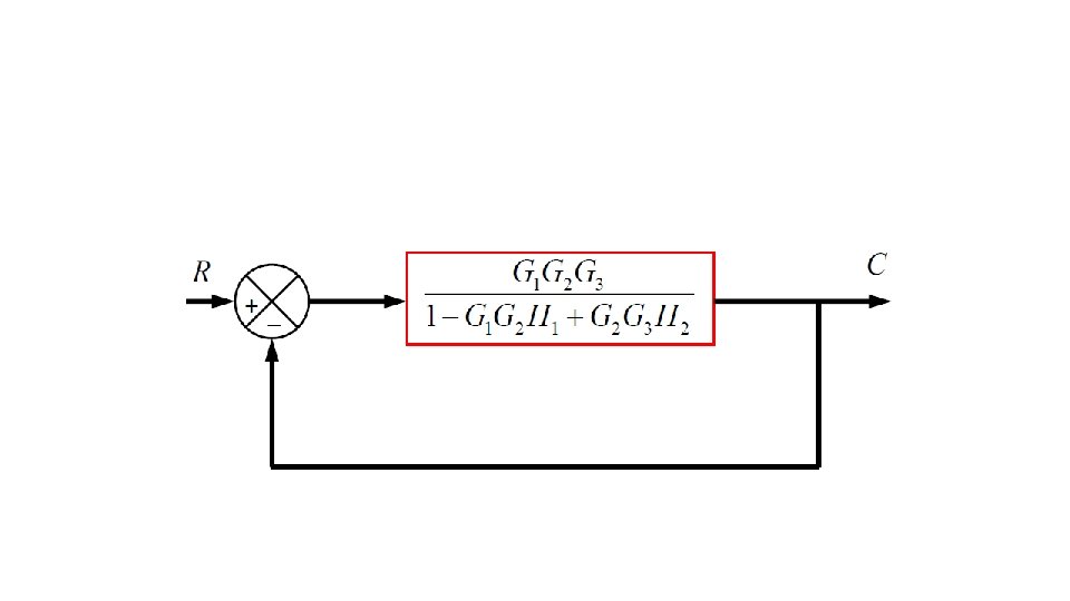
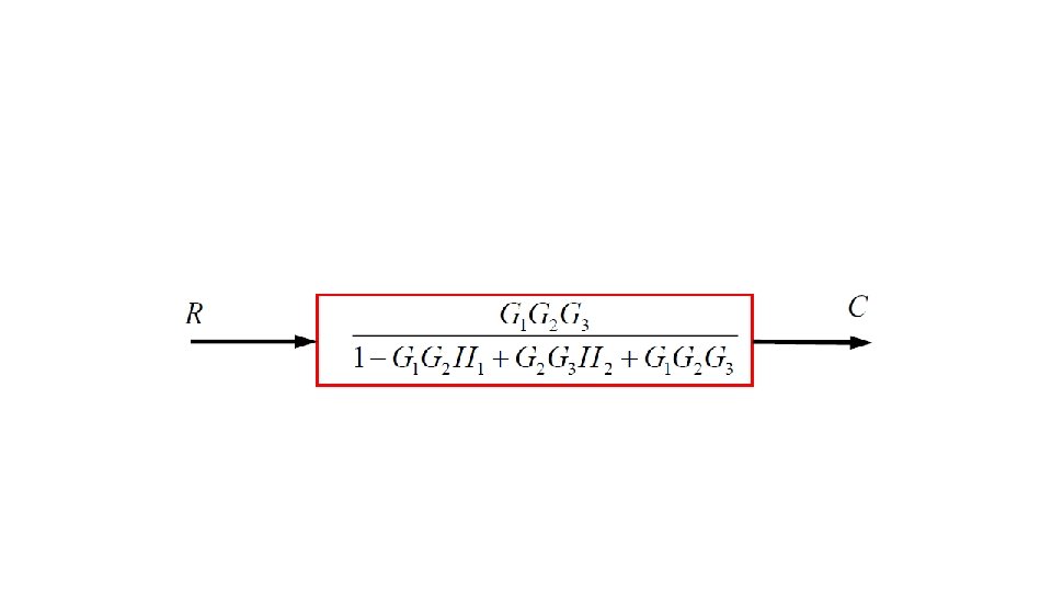

Find the transfer function of the following block diagrams:
- Slides: 61