
Unit 14 State Modeling Prof Arjun V Bala
Unit – 14 State Modeling Prof. Arjun V. Bala 9624822202 arjun. bala@darshan. ac. in Computer Engineering OOP JAVA 2150704 Semester 5 Darshan Institute of Engineering & Technology
State Modeling § State Diagram explains behavior of the system. § A State Diagram is a graph whose nodes are states and arcs are transition between the states caused by the event. § State Modeling examines changes to the object and their relationship over time. § The behavior of an entity is not only a direct consequence of its input, but it also depends on its preceding state. § The history of an entity can best be modeled by a finite state diagram. 2 Unit-14 State Modeling Darshan Institute of Engineering & Technology
State Modeling (Cont. ) § State diagram can show the different states of an entity also how an entity responds to various events by changing from one state to another. § The major dynamic modeling concepts are events, which represent external stimuli, and states, which represent values of objects. § State Diagram is a standard computer science concept/a graphical representation that relates events and states. § State model describes: • • Sequence of operation that occur in response of external stimuli. What the specific operation do. What they operate on. How that operation are implemented Unit-14 State Modeling 3 Darshan Institute of Engineering & Technology
Events § Every event is a unique occurrence at a point in time, It causes transitions between states. § Events might be related or unrelated. If two events are casually unrelated they are said to be concurrent. § Event often corresponds to verb in past tense. i. e. door_opened, door_closed event. § Events include error conditions like motor jammed, transaction aborted, and timeout, etc. § In software modeling system we do not try to establish an ordering between concurrent events because they can occur in any order. § The most common type of events is the signal event, the change event, and the time event. 4 Unit-14 State Modeling Darshan Institute of Engineering & Technology
i) Signal Event § Grouping every event into event classes and gives each event class a name to indicate common structure and behavior is known as Signal Event. § It is a one-way transmission of information from one object to another. It is event of sending or receiving signal. § The UML notation is the keyword signal in guillemets (<< >>) above the signal class name in the top section of a box. 5 Unit-14 State Modeling Darshan Institute of Engineering & Technology
ii) Change Event § Change event is caused by the satisfaction of Boolean expression. Whenever the expression changes from false to true the event happens. § The UML notation for a change event is the keyword when followed by a parenthesized Boolean expression. § Example : When ( marks < 50% ) When ( room temp. < heating set. Point) When ( battery power<lower limit) When ( tire pressure < min. pressure) 6 Unit-14 State Modeling Darshan Institute of Engineering & Technology
iii) Time Events § A time event is an event caused by the occurrence of an absolute time or the elapse of a time interval. § The UML notation for an absolute time is the keyword when followed by a parenthesized expression involving time. § This event is caused by the occurrence of an absolute time or the elapsed of a time interval. § The notation for a time interval is the keyword after followed by a parenthesized expression that evaluates to time duration. 7 Unit-14 State Modeling Darshan Institute of Engineering & Technology
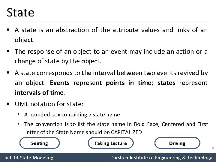
State § A state is an abstraction of the attribute values and links of an object. § The response of an object to an event may include an action or a change of state by the object. § A state corresponds to the interval between two events revived by an object. Events represent points in time; states represent intervals of time. § UML notation for state: • A rounded box containing a state name. • The convention is to list the state name in Bold Face, Centered and First Letter of the State Name should be CAPITALIZED Seating Unit-14 State Modeling Taking Lecture Driving 8 Darshan Institute of Engineering & Technology
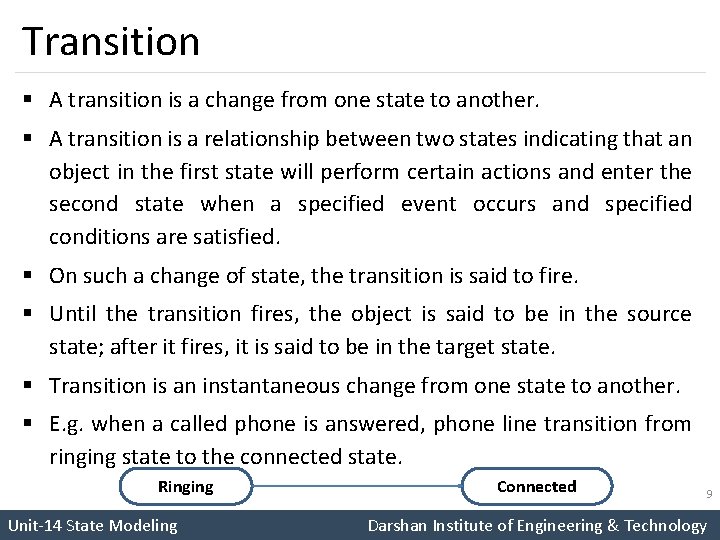
Transition § A transition is a change from one state to another. § A transition is a relationship between two states indicating that an object in the first state will perform certain actions and enter the second state when a specified event occurs and specified conditions are satisfied. § On such a change of state, the transition is said to fire. § Until the transition fires, the object is said to be in the source state; after it fires, it is said to be in the target state. § Transition is an instantaneous change from one state to another. § E. g. when a called phone is answered, phone line transition from ringing state to the connected state. Ringing Unit-14 State Modeling Connected 9 Darshan Institute of Engineering & Technology
Guard Condition § Guard condition is a Boolean expression that must be true in order for a transition to occur. § Guard condition is the condition fired when event occurs, but only if guard condition is true. § Guard condition is checked only once, at a time event occurs and transition fires if condition is true. § If the condition is true later on, the transition does not fire then. § UML notation for Guard condition is condition written inside square brackets [ ] on transition and followed by an event. § It is an optional condition. 10 Unit-14 State Modeling Darshan Institute of Engineering & Technology
Types of State Diagram § There are two types of state diagram • Sample State Diagrams § State diagram with continuous loop § Sample state diagram represents object with infinite life. • One-Shot State Diagrams § One-short diagram represent object with finite lives and have initial and final states. § Initial state is entered on creation of an object while entry of final state implies destruction of an object. You can indicate initial and final states via entry and exit points. § Entry points (hollow circles) and exit points (circle enclosing an “x”) appear on the state diagram’s perimeter and may be named. Unit-14 State Modeling 11 Darshan Institute of Engineering & Technology
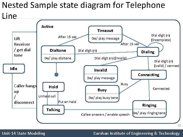
Nested Sample state diagram for Telephone Line Active Lift Receiver / get dial tone Timeout After 15 sec Do/ play message After 15 sec Dialtone Do/ play dialtone Idle Dial digit (n) Dialing Dial digit (n) [invalid] Invalid Talking Busy Dial digit (n) [valid] / connect Connecting Do/ play message Caller hangs Hold up Unhold call / Put on hold disconnect Dial digit (n) [incomplete] Connected Do/ play busy tone Ringing Callee answers / enable speech Do/ play ringing tone 12 Unit-14 State Modeling Darshan Institute of Engineering & Technology
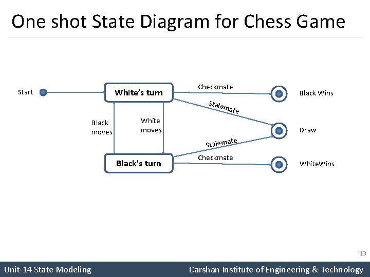
One shot State Diagram for Chess Game White’s turn Start Checkmate Black Wins Stale mate Black moves White moves Draw te Stalema Black’s turn Checkmate White. Wins 13 Unit-14 State Modeling Darshan Institute of Engineering & Technology
Activity Effects § The effect is a reference to a behavior that is executed in response to an event. § An activity is the actual behavior that can be invoked by any number of effects. E. g. disconnect Phone Line might be an activity that is executed in response to hang up event. § Activities can also represent internal control operations, such as setting attributes or generating other events. Such activities have no real-world counterparts but instead are mechanisms for structuring control within an implementation. E. g. program might increment an internal counter every time when specific event occurs. § State diagram activity is denoted as slash (“/”) and name or description of the activity, following the event that causes it. Unit-14 State Modeling 14 Darshan Institute of Engineering & Technology
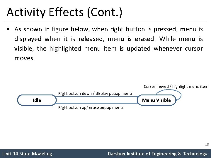
Activity Effects (Cont. ) § As shown in figure below, when right button is pressed, menu is displayed when it is released, menu is erased. While menu is visible, the highlighted menu item is updated whenever cursor moves. Cursor moved / highlight menu item Right button down / display popup menu Idle Menu Visible Right button up/ erase popup menu 15 Unit-14 State Modeling Darshan Institute of Engineering & Technology
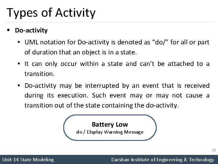
Types of Activity § Do-activity • UML notation for Do-activity is denoted as “do/” for all or part of duration that an object is in a state. • It can only occur within a state and can’t be attached to a transition. • Do-activity may be interrupted by an event that is received during its execution. Such event may or may not cause a transition out of the state containing the do-activity. Battery Low do / Display Warning Message 16 Unit-14 State Modeling Darshan Institute of Engineering & Technology
Types of Activity (Cont. ) § Entry and Exit Activities • We can also bind activities to entry or to exit from a state as an alternative to show the activity on transition. • There is no difference between binding an activity to a transition or to a state. • When the state is entered by an incoming transition, entry activity is performed. • If incoming transition already has an activity, it is performed first. • Exit activities are less common compared to entry activities and occasionally useful. • Whenever state is exited, by any outgoing transition, the exit activity is performed first. 17 Unit-14 State Modeling Darshan Institute of Engineering & Technology
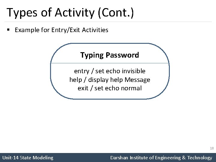
Types of Activity (Cont. ) § Example for Entry/Exit Activities Typing Password entry / set echo invisible help / display help Message exit / set echo normal 18 Unit-14 State Modeling Darshan Institute of Engineering & Technology
Types of Activity (Cont. ) § If a state has multiple activities, they are performed in following order: 1. Activities on incoming transition 2. Entry Activities 3. Do-Activities 4. Exit Activities 5. Activities on outgoing transition 19 Unit-14 State Modeling Darshan Institute of Engineering & Technology
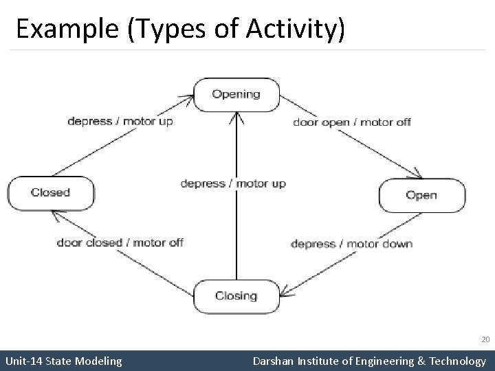
Example (Types of Activity) 20 Unit-14 State Modeling Darshan Institute of Engineering & Technology
- Slides: 20