UNIT 1 Indicating recording and controlling Instruments commonly


 • Torque on")


 The greater")


- Slides: 58
UNIT 1 Indicating , recording and controlling Instruments commonly used in Process industries.
CLASSIFICATION OF INSTRUMENTS Electrical instruments may be divided into two categories, that are; 1. Absolute instruments, 2. Secondary instruments. - Absolute instruments gives the quantity to be measured in term of instrument constant & its deflection. - In Secondary instruments the deflection gives the magnitude of electrical quantity to be measured directly. These instruments are required to be calibrated by comparing with another standard instrument before putting into use.
CLASSIFICATION OF INSTRUMENTS
CLASSIFICATION OF INSTRUMENTS Electrical measuring instruments may also be classified according to the kind of quantity, kind of current, principle of operation of moving system. CLASSIFICATION OF SECONDARY INSTRUMENTS • Secondary instruments can be classified into three types; i. Indicating instruments; ii. Recording instruments; iii. Integrating instruments.
CLASSIFICATION OF SECONDARY INSTRUMENTS - Indicating Instruments: It indicate the magnitude of an electrical quantity at the time when it is being measured. The indications are given by a pointer moving over a graduated dial.
CLASSIFICATION OF SECONDARY INSTRUMENTS - Recording Instruments: The instruments which keep a continuous record of the variations of the magnitude of an electrical quantity to be observed over a defined period of time.
CLASSIFICATION OF SECONDARY INSTRUMENTS - Integrating Instruments: The instruments which measure the total amount of either quantity of electricity or electrical energy supplied over a period of time. For example energy meters.
Types of Indicating Instruments • • • PMMC MI Electrodynamometer Hot wire Induction type
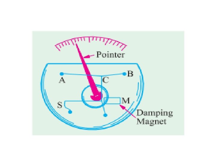
ESSENTIALS OF INDICATING INSTRUMENTS Indicating instruments are those which indicate the value of quantity that is being measured at the time at which it is measured. Such instruments consist essentially of a pointer which moves over a calibrated scale & which is attached to a moving system pivoted in bearing. The moving system is subjected to the following three torques: 1. A deflecting ( or operating) torque; 2. A controlling ( or restoring) torque; 3. A damping torque.
DEFLECTING TORQUE - The deflecting torque is produced by making one of the magnetic, heating, chemical, electrostatic and electromagnetic induction effect of current or voltage and cause the moving system of the instrument to move from its zero position. - The method of producing this torque depends upon the type of instrument.
CONTROLLING TORQUE - The magnitude of the moving system would be some what indefinite under the influence of deflecting torque, unless the controlling torque existed to oppose the deflecting torque. - It increases with increase in deflection of moving system. - Under the influence of controlling torque the pointer will return to its zero position on removing the source producing the deflecting torque. - Without controlling torque the pointer will swing at its maximum position & will not return to zero after removing the source.
- Controlling torque is produced either by spring or gravity control. Spring Control: • When the pointer is deflected one spring unwinds itself while the other is twisted. This twist in the spring produces restoring (controlling) torque, which is proportional to the angle of deflection of the moving systems.
Spring Control
Gravity Control • In gravity controlled instruments, a small adjustable weight is attached to the spindle of the moving system such that the deflecting torque produced by the instrument has to act against the action of gravity. • Thus a controlling torque is obtained. This weight is called the control weight. Another adjustable weight is also attached is the moving system for zero adjustment and balancing purpose. This weight is called Balance weight.
Advantages of Gravity control • Cheaper than spring controlled instrument. • Unaffected by temperature variations. • It is not subjected to fatigue. Disadvantages • Scale is not uniform • Instrument should be kept in vertical position.
DAMPING TORQUE • We have already seen that the moving system of the instrument will tend to move under the action of the deflecting torque. • But on account of the control torque, it will try to occupy a position of rest when the two torques are equal and opposite. • However, due to inertia of the moving system, the pointer will not come to rest immediately but oscillate about its final deflected position as shown in figure and takes appreciable time to come to steady state. • To overcome this difficulty a damping torque is to be developed by using a damping device attached to the moving system.
DAMPING TORQUE • The damping torque is proportional to the speed of rotation of the moving system, that is • Depending upon the degree of damping introduced in the moving system, the instrument may have any one of the following conditions as depicted in above graph.
DAMPING TORQUE 1. Under damped condition: The response is oscillatory 2. Over damped condition: The response is sluggish and it rises very slowly from its zero position to final position. 3. Critically damped condition: When the response settles quickly without any oscillation, the system is said to be critically damped or dead beat. The damping torque is produced by the following methods: 1. Air Friction Damping 2. Fluid Friction Damping
Moving-Coil instrument • There are two types of moving coil instruments namely, permanent magnet moving coil type which can only be used for direct current, voltage measurements. • The dynamometer type which can be used on either direct or alternating current, voltage measurements.
PERMANENT MAGNET MOVING COIL “The principle operation of PMMC is based upon the principle of current carrying conductor is placed in a magnetic field it is acted upon by force which tends to move it. ”
Deflecting torque • Force on one side of the coil F=Biln(N) • Torque on each side of the coil T 1=F. b/2=Biln. b/2 • Total deflecting torque exerted on the coil Td=2 T 1 =2 Biln. b/2 Td= Bilnb Nm Td=k 1* i
Control Torque • Tc=Ks*ø • Pointer will settle in a position where Td=Tc Ks*ø=K 1 i ø=K i Where K=K 1/Ks.
Damping Torque • When the aluminium coil moves with the coil in the field of the permanent magnet , a voltage is induced causing eddy currents to flow. • According to Lenz law this current opposes the force causing its motion which creates the damping torque.
Electrodynamic type • This instrument is suitable for the measurement of direct and alternating current, voltage and power. • The deflecting torque in dynamometer is relies by the interaction of magnetic field produced by a pair of fixed air cored coils and a third air cored coil capable of angular movement and suspended within the fixed coil.
DYNAMOMETER
Features • It is equally accurate on AC and DC. • It has a linear scale • The readings of the instrument may be affected by stray magnetic field. • It is used as a transfer instrument , that is its calibration is the same on ac and dc.
Moving-iron instrument • An attraction type of moving-iron instrument is shown diagrammatically in Figure. When current flows in the solenoid, a pivoted soft-iron disc is attracted towards the solenoid and the movement causes a pointer to move across a scale. • In the repulsion type moving-iron instrument shown diagrammatically in Figure, two pieces of iron are placed inside the solenoid, one being fixed, and the other attached to the spindle carrying the pointer.
28
Moving-iron instrument
30
Advantages: • The instruments are suitable for use in a. c and d. c circuits. • The instruments are robust, owing to the simple construction of the moving parts. • The stationary parts of the instruments are also simple. • Instrument is of low cost as compared to moving coil instrument. • Torque/weight ratio is high, thus less frictional error. 31
Errors: i. Errors due to temperature variation. ii. Errors due to friction is quite small as torque-weight ratio is high in moving-iron instruments. iii. Stray fields cause relatively low values of magnetizing force produced by the coil. Efficient magnetic screening is essential to reduce this effect. 32
iv. Error due to variation of frequency causes change of reactance of the coil and also changes the eddy currents induced in neighbouring metal. v. Deflecting torque is not exactly proportional to the square of the current due to non-linear characteristics of iron material. 33
HOT WIRE TYPE • It is based on the heating effect of current. • It consist of platinum-iridium (it can withstand oxidation at high temperatures) wire. • When current is through wire, it expands according to I 2 R formula. • This produces sag in the wire and pointer is attached with this wire which in result deflects.
Advantages of Hot wire type instruments • Can be used for both dc and ac • Unaffected by stray magnetic fields • Readings are independent of frequency and waveform Disadvantages • They are sluggish owing to the time taken by the wire to heat up • Their zero position requires frequent adjustments • They are fragile • Power consumed is more compared to PMMC
INDUCTION TYPE INSTRUMENT • • Such instruments are suitable for ac measurements only in these instruments the deflecting torque is produced by the eddy currents induced in an aluminum or copper disc or drum by the flux created by an electro-magnet. The main advantages of such instruments are that (i) a full scale deflection can be obtained giving long and scale (ii) the effect of stray magnetic field is small; (iii) damping is easier and effective. open
INDUCTION TYPE INSTRUMENT • These instruments have got some serious disadvantages (i) The greater deflection causes more stresses in the control springs. (ii) Variation in supply frequency and temperature may cause serious errors unless compensating device is employed. (iii) These instruments are costlier and consume more power • Such instruments are mostly used as watt-meters or energy meters.
INDUCTION TYPE INSTRUMENT
INDUCTION TYPE INSTRUMENT • • • Induction type wattmeter consists of two laminate electromagnets known as shunt electromagnet and series electromagnet respectively. Shunt magnet is excited by the current proportional to the voltage across load flowing through the pressure coil and series magnet is excited by the load current flowing through the current coil. A thin disc made of Cu or Al, pivoted at its centre, is placed between the shunt and series magnets so that it cuts the flux from both of the magnets.
INDUCTION TYPE INSTRUMENT • • • The deflection torque is produced by interaction of eddy current induced in the disc and the inducing flux in order to cause the resultant flux in shunt magnet to lag in phase by exactly 90° behind the applied voltage. One or more copper rings, known as copper shading bond are provided on one limb at the shunt magnet. The pressure coil circuit of induction type instrument is made as inductive as possible so that the flux of the shunt magnet may lag by 90° behind the applied voltage.
Comparison Analog meters Digital meters • Require no power supply • Suffer less from electrical noise • Simple and inexpensive • Less accurate • Larger in size • Has internal battery • Has more noise problems • Comparitively expensive • More accurate • Size is small
Digital meters • The 3 classes of digital meters are 1. Panel meters 2. Benchtype meters 3. System meters. • All employ some type of A/D converter • Usually panel meters are dedicated to single function whereas the other two are multimeters.
Digital Multimeter
Digital Panel meters • They are available in a wide variety of special purpose functions. • Units are available to accept inputs such as dc volts, ac volts, line voltage, strain gauge bridges, RTD, thermocouples of many types and frequency inputs.
Bench and System type digital meters • Bench type are just like DMM. • System type DMMs are an alternative to PC based data acquisition system or data loggers , providing multichannel voltage, current , resistance , temperature and frequency measurement capability. • Data analysis features and sampling rates do not match PC based systems but may be sufficient and cost effective for many applications.
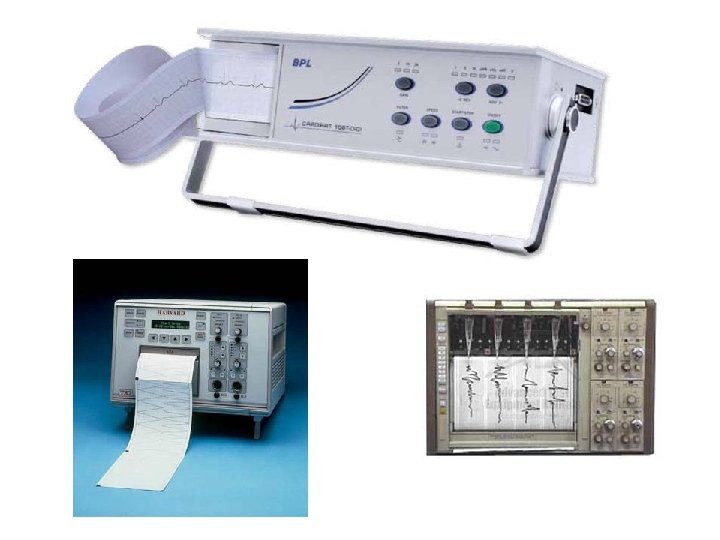
RECORDING INSTRUMENTS
Electromechanical servotype XT recorders • It can be used for indicating and simultaneous recording of a voltage against time. • The instrument servomechanism is designed so that a displacement x 0 tracks the voltage e accurately. • It uses ac/dc amplifiers , ac /dc motors, rotary / translational motors , various mechanical drive arrangements , assorted writing schemes and different displacement transducers.
Servotype pen recorder
• Throw away fiber ink pens are used the most but some recorders use heated styli and heat sensitive paper. • Multichannel operation is possible with reduced width side by side or full width overlapping , the limit is about six pens. • Static accuracy is about 0. 1% full scale.
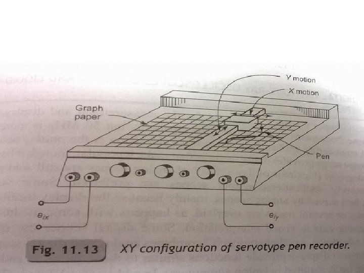
Electromechanical servotype XY recorders • To cross plot one variable against another , XY configuration is used. • Here the paper is still and two independant servos move the pen horizontally and vertically. • Becoming obsolete • The xy function is mainly implemented with PC based data acquisition system, that use a CRT to display , an ink jet or laser printer for hard copy. • Plotters used to produce engineering drawings from CAD software.
Thermal array recorders • These recorders have replaced pen/stylus and optical oscillograph for medium and high speed data by eliminating the messy ink and the moving parts except for the paper drive. • Here heated elements write on heat sensitive paper. • Single and multichannel data is sampled and stored at high speed and then read out at slow speed.
Virtual Instruments • Many of the measurement functions provided by actual hardware available with PC based data acquisition system and associated software as virtual instruments. • VI that emulate DMMs, scopes, spectrum analyzer, arbitrary FG , data loggers , strip chart recorders etc. . . are possible. • The PC monitor can display a graphic image that looks like the real instruments panel. • Such VI are widely used in process control panels and aircraft cockpits.
Magnetic Tape and Disk Recorders / Reproducers • It has a no. of unique features derived mainly from its ability to record a voltage , store it for any time and then reproduce it in electrical form as its original occurrence. • Recording methods include direct, FM , PDM and digital techniques. • The tape is made of thin plastic coated with Iron oxide. • The Iron oxide particles retain a state of permanent magnetization proportional to the current.
Tape Recorder/Reproducer
Record / Reproduce heads