Unit 1 Basics of Fluid Power and Pumps
 Dr. S. S.")
Unit 1 - Basics of Fluid Power and Pumps (part 1) Dr. S. S. Deshpande, Associate Professor (Mechanical Engineering) GCOER Avasari


� Basics � Advantages and limitation � Fluid power distribution � Standard symbols � Energy loss in Hydraulic systems �

� Pump- ◦ ◦ ◦ ◦ Types Classification Vane pump Gear pump Radial pump Axial plunger pump Screw pump � Power and efficiency calculations � Characteristic curves

Losses � Friction � Leakages � Losses due to friction increase with rise in viscosity � Losses due to leakage decrease with rise in viscosity

Head loss � λ= coefficient of frictional loss � hp= head loss ……. meters of fluid � V= velocity …m/s � l= length of pipe …. . m � d= diameter of pipe …. m � g= acceleration due to gravity

�λ depends of � Type of fluid flow � Inner surface finish � Viscosity � Laminar flow, Polished pipes λ =64/Re (Re 2000 to 2300) � Laminar flow, other pipes λ =6. 75/Re (Re < 1200) � turbulent flow, other pipes λ =0. 316/Re (Re >2500) � For laminar and turbulent 1200<Re <2000

Losses in Pipe fittings � K= factor of fitting
 � ρ= density (kg/m 3) � If the formula")
� Pressure drop (Kg/m 2) � ρ= density (kg/m 3) � If the formula is multiplied by g … Kg/m 2 unit becomes N/m 2 � if cm is used …. .

Pumps � Heart � Converts mechanical power of the prime mover to hydraulic power by pressuring the oil � Fluid is supplied to various parts � Flow rate, pressure � As the fluid encounters load/resistance, pressure is developed

Cavitation � Occurs in suction line of pump � Vapor pressure � Bubble formation � When bubble collapse, vacuum is created � Liquid from surrounding region rushes to this spot � create a momentary high pressure � Damages metal part
 � Outlet (delivery) � Continuous supply of fluid at inlet by")
� Inlet (suction) � Outlet (delivery) � Continuous supply of fluid at inlet by sump
 � Rotodynamic pumps (hydro dynamic) � Hydrostatic")
classification � Positive displacement of pump (hydrostatic) � Rotodynamic pumps (hydro dynamic) � Hydrostatic � Fix volume is taken in the pumping chamber � No change in kinetic energy of fluid � Pure pressure energy is in output side � No slippage of fluid � Always deliver constant volume of pump irrespective of pressure /resistance

� More restriction at delivery valve , more pressure � The flow rate is dependent of speed alone � Discharge is in discrete volumes and not continuous � Based on configuration ◦ Reciprocating type ◦ Rotary type � Based on delivery ◦ Fixed delivery pumps ◦ Variable delivery pumps

Reciprocating type � Classification ◦ Axial plunger type ◦ Radial Plunger type ◦ Series plunger type

Rotary type � Vane pump � Gear Pump � Screw Pump

Positive Disp pumps based on delivery � Fixed ◦ ◦ ◦ delivery (at fixed rpm, rate of flow is fixed) fixed geometrical displacement But flow control valve can be used Simple in construction Volume delivered per revolution can not be changed � Variable delivery ◦ Varying geometrical displacement ◦ Volume delivered per revolution can be changed ◦ Complex in design, construction, operation

Rotodynamic Pumps � External work is imparted to the fluid in the control volume in the form of kinetic energy � Fast rotating impeller � Kinetic energy increases � Fluid starts moving at high velocity � Velocity head is converted into pressure head � Fluid moves continuously � Discharge is continuous not discrete � Continuous process of suction, rotary motion, discharge � Pressure variation is continuous from the suction to the discharge line

Positive displacement Rotodynamic pump Delivers in discrete volumes Continuous One delivery per stroke Suction and delivery is continuous Low pressure and high pressure regions No such regions. Variation is continuous Work done is in the form of pressure energy Work done is in the form of kinetic energy No limit to maximum pressure Limit to max pressure
 � Components ◦ ◦ Rotor with radial slots")
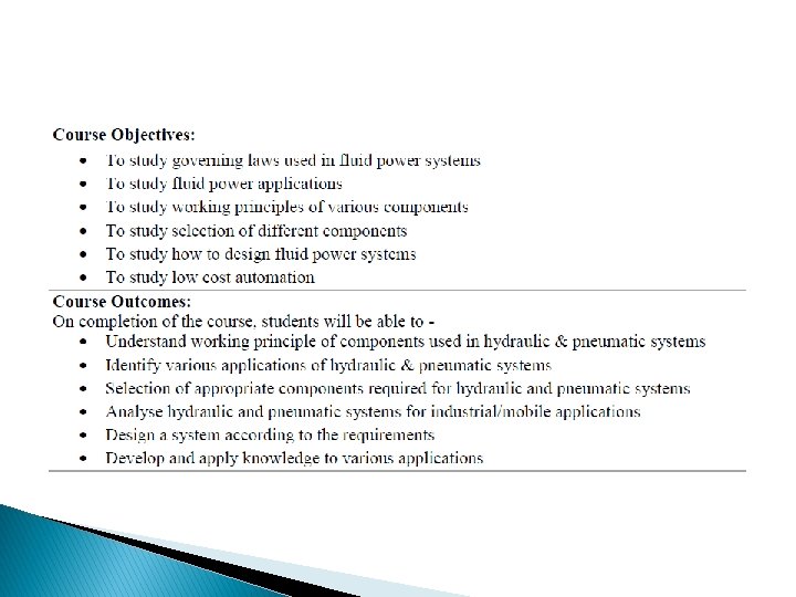
Vane pumps � (siding vane pumps) � Components ◦ ◦ Rotor with radial slots Sliding vanes Circular ring or casing (stator) Port plates with kidney shaped inlet and delivery ports

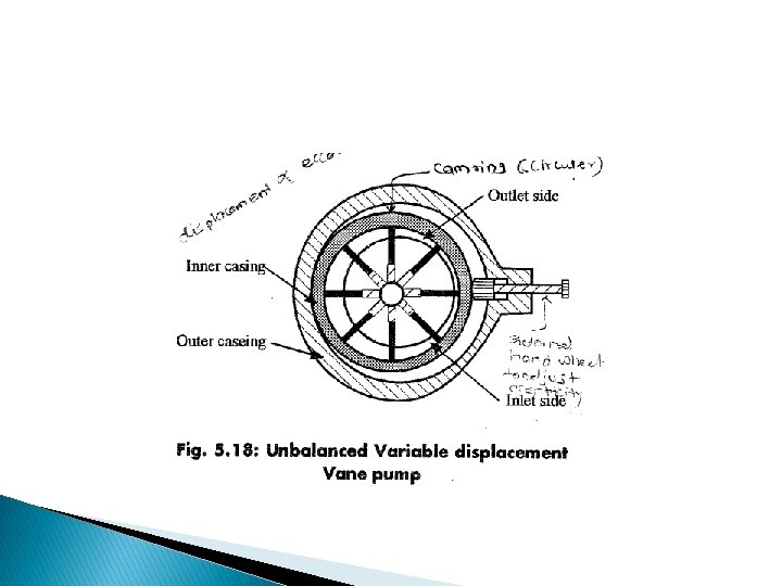
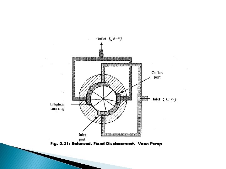
Classification of vane pumps � Fixed displacement ◦ Unbalanced ◦ Balanced (elliptical and not circular) �Rotor is mounted co axial with the stator �Diametrically opposite regions

Components of Vane Pumps
")
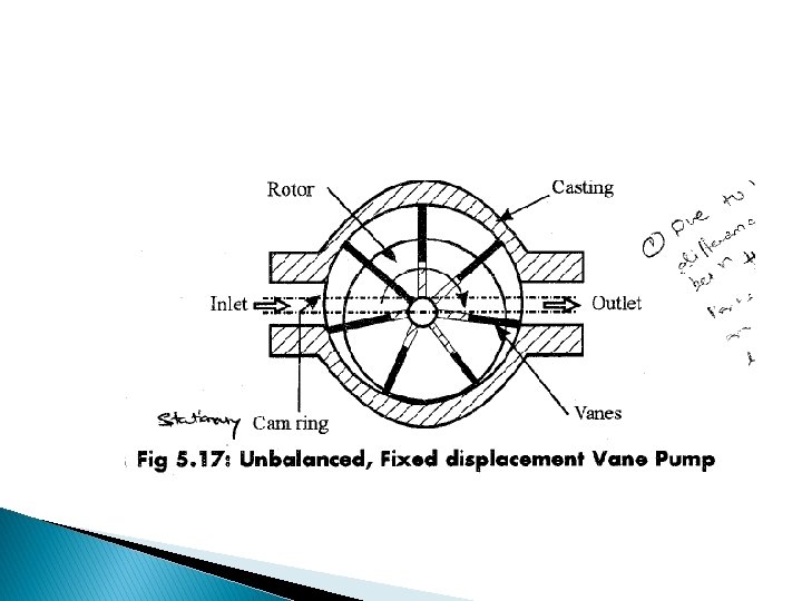
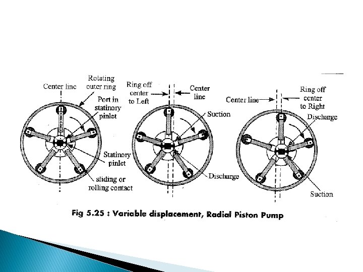
Variable displacement. Zero discharge (zero eccentricity)
")
Variable displacement. Max discharge position (max eccentricity)

Variable displacement Eccentricity between rotor and casing can be adjusted

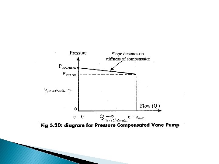
Pressure Compensated

Simplified diagram

Pressure compensated � Discharge pressure remains constant irrespective of

Geometric displacement of a vane pump � Q=4πR ben � R= radius of casing � b= breadth of vane � e= eccentricity � n= rpm

Characteristics of vane pumps
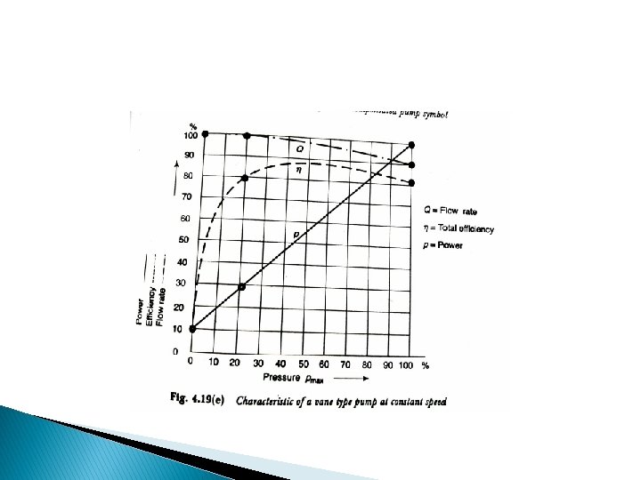

Salient features of Vane pumps � Medium to high pressure applications � Production is easy � Variable discharge can be easily obtained � Flow is more ripple free � Low noise

Drawbacks of vane pumps � Unbalanced rotor as high and low pressure to the two sides � Suction side below atmospheric � Delivery side, very high pressure � Vane loading, wear and tear, friction , losses � Vane loading centrifugal action/ spring force � Connecting to system pressure (rotor and vanes)

Gear Pump � Positive displacement pump � High pressure � Low discharge � Simple in design � Cheap � Handle variety fluids (not water) � Classification of gear pumps

Basic principle of working of Gear Pump Note the direction of rotation and direction of flow

Performance characteristics of external gear pump On Y axis Discharge in LPM

Drawback of gear pump � Excessive side loading on the shaft due to difference in pressure � Side thrust on gear shaft due to helix angle in helical gears ◦ Herring bone gears are suggested

Helical gear pumps � Superior to spur gear pumps � Overlapping of teeth- continuous , smooth, uniform discharge � Less noisy � Side thrust is main drawback

Herring bone gear pump � Double helix � Side thrust is eliminated

Internal gear pumps

� The divider is stationary � Pinion rotates so the internal gear also rotates in same direction � Suction and discharge ports are at back side
")
Gerotor Pump (Internal meshing)

Screw Pumps
 � Driving screw , driven screw � Axial")
� Screws mesh (like gears mesh) � Driving screw , driven screw � Axial flow � Advantages ◦ ◦ ◦ ◦ Wide range of flow and pressure Wide range of liquids Low internal velocities Low vibration and noise Pulsation free Rugged and compact] High speed operation

Disadvantages of screw pumps � High Cost
 � Pumping action is caused by a special cam arrangement. �")
Plunger (piston pumps) � Pumping action is caused by a special cam arrangement. � More cylinders, more uniform flow � Cylinders can be arranged in ◦ Axial plunger �Bent axis type �Swash plate type �Rotating cylinder type �Rotating swash plate type ◦ Radial plunger ◦ Inline plunger

Bent Axis

Swash plate type

Rotating cylinder type

Rotating swash plate type

Pump performance

Power � Power= �A pressure x discharge separate presentation will be shared on numerical/ problems on pumps based on SPPU syllabus

Factors affecting the selection of type of pump �allowable pump speeds �Max and safe system pressure in working conditions �Performance characteristics �Efficiency �Durability �Operating reliability �Operation at variable loads/speeds

�Cost �Variable �Wear discharge capability �Temperature �Noise of operation �Manufacturing characteristics �Power to weight ratio �compactness

� Thanks
- Slides: 61