
Unit 047 Workholding and Toolholding Devices for the




- Slides: 38
Unit 047 Workholding and Toolholding Devices for the Lathe
Introduction • This chapter discusses: – Devices used to mount workpieces securely to the lathe (workholding devices: chucks, collets, lathe centers, and mandrels) – Devices used to mount cutting tools (toolholding devices: tool posts, toolholders, and Morse taper accessories)
Workholding Devices • Jaw-type chucks clamp workpiece to spindle by applying pressure on multiple sides • Independent chucks' jaws advance and retract separately, universal chucks' simultaneously • Types include three-jaw and four-jaw
FIGURE 5. 2. 1 Various styles of jaw-type lathe chucks, including a three-jaw, four-jaw, and six-jaw chuck. © Cengage Learning 2012
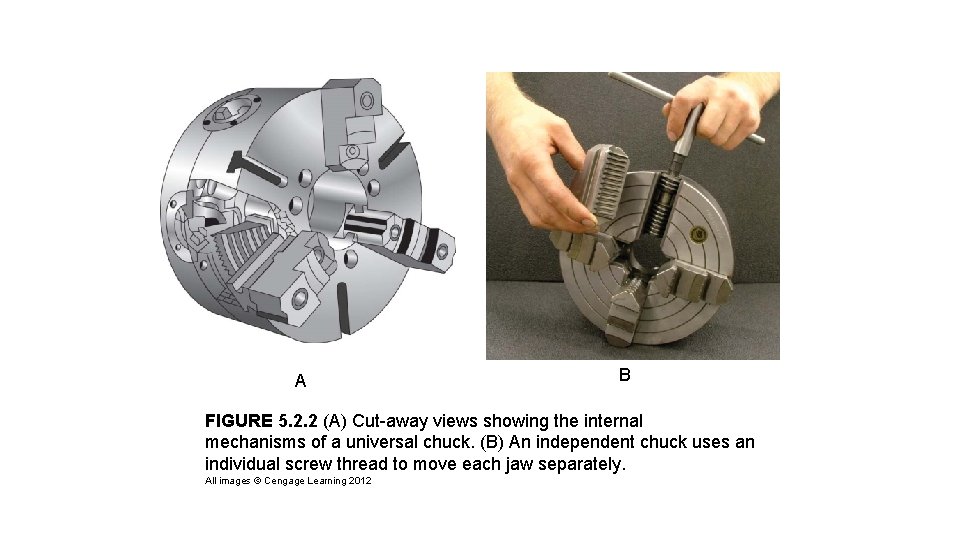
A B FIGURE 5. 2. 2 (A) Cut-away views showing the internal mechanisms of a universal chuck. (B) An independent chuck uses an individual screw thread to move each jaw separately. All images © Cengage Learning 2012
FIGURE 5. 2. 3 A chuck being used to grip a workpiece by its inside diameter. © Cengage Learning 2012 FIGURE 5. 2. 4 A universal three-jaw chuck. © Cengage Learning 2012
FIGURE 5. 2. 5 Round and hexagonal workpieces can be properly secured in a three-jaw chuck. All images © Cengage Learning 2012
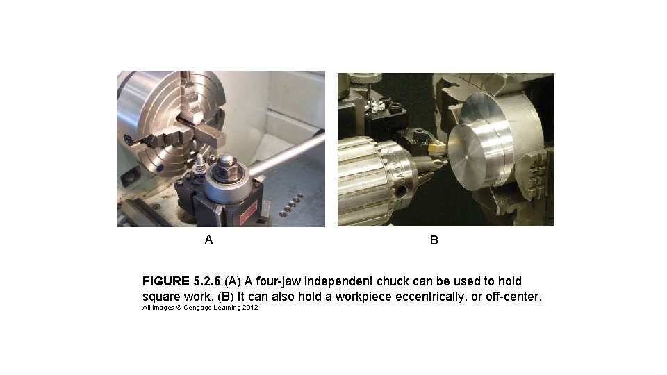
A B FIGURE 5. 2. 6 (A) A four-jaw independent chuck can be used to hold square work. (B) It can also hold a workpiece eccentrically, or off-center. All images © Cengage Learning 2012
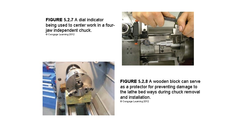
FIGURE 5. 2. 7 A dial indicator being used to center work in a fourjaw independent chuck. © Cengage Learning 2012 FIGURE 5. 2. 8 A wooden block can serve as a protector for preventing damage to the lathe bed ways during chuck removal and installation. © Cengage Learning 2012
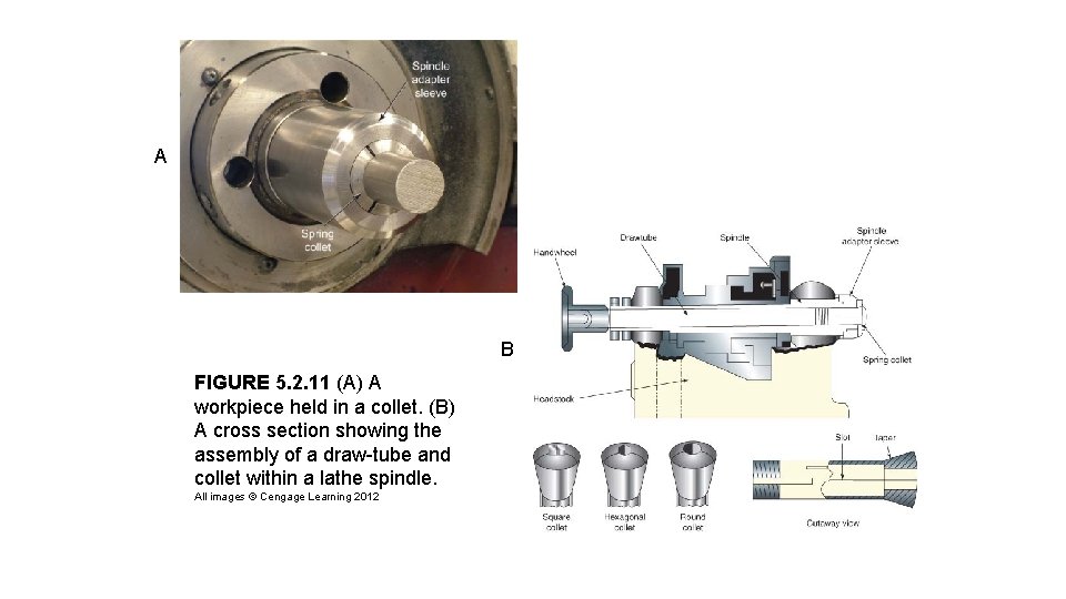
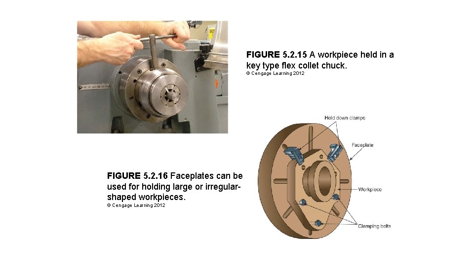
Workholding Devices (cont'd. ) • Collets have holes matching size and shape of work • Types: spring and flex • Faceplates mount to headstock spindle to secure irregularly shaped workpieces
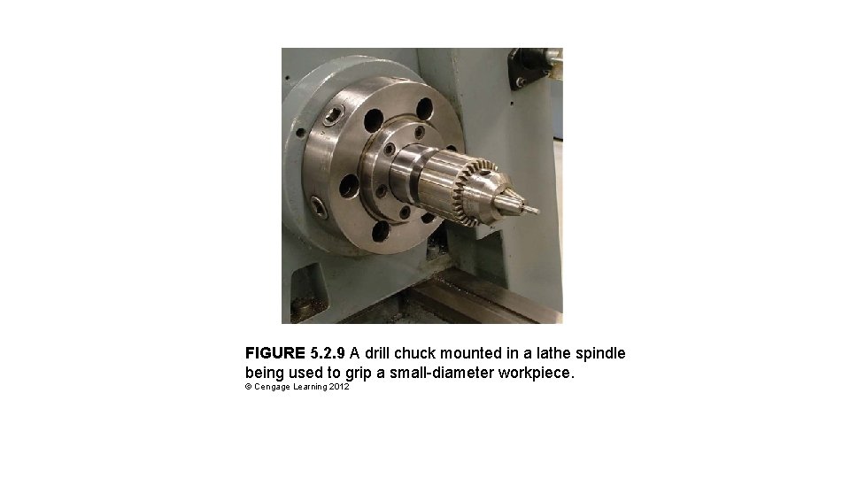
FIGURE 5. 2. 9 A drill chuck mounted in a lathe spindle being used to grip a small-diameter workpiece. © Cengage Learning 2012
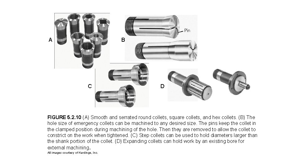
A B C D FIGURE 5. 2. 10 (A) Smooth and serrated round collets, square collets, and hex collets. (B) The hole size of emergency collets can be machined to any desired size. The pins keep the collet in the clamped position during machining of the hole. Then they are removed to allow the collet to constrict on the work when tightened. (C) Step collets can be used to hold diameters larger than the shank portion of the collet. (D) Expanding collets can hold work by an existing bore for external machining. All images courtesy of Hardinge, Inc.
A B FIGURE 5. 2. 11 (A) A workpiece held in a collet. (B) A cross section showing the assembly of a draw-tube and collet within a lathe spindle. All images © Cengage Learning 2012
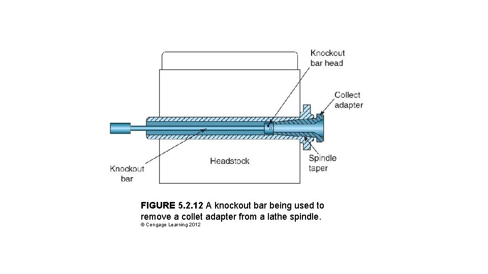
FIGURE 5. 2. 12 A knockout bar being used to remove a collet adapter from a lathe spindle. © Cengage Learning 2012
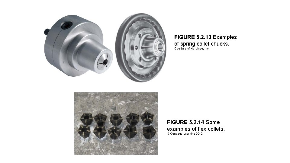
FIGURE 5. 2. 13 Examples of spring collet chucks. Courtesy of Hardinge, Inc. FIGURE 5. 2. 14 Some examples of flex collets. © Cengage Learning 2012
FIGURE 5. 2. 15 A workpiece held in a key type flex collet chuck. © Cengage Learning 2012 FIGURE 5. 2. 16 Faceplates can be used for holding large or irregularshaped workpieces. © Cengage Learning 2012
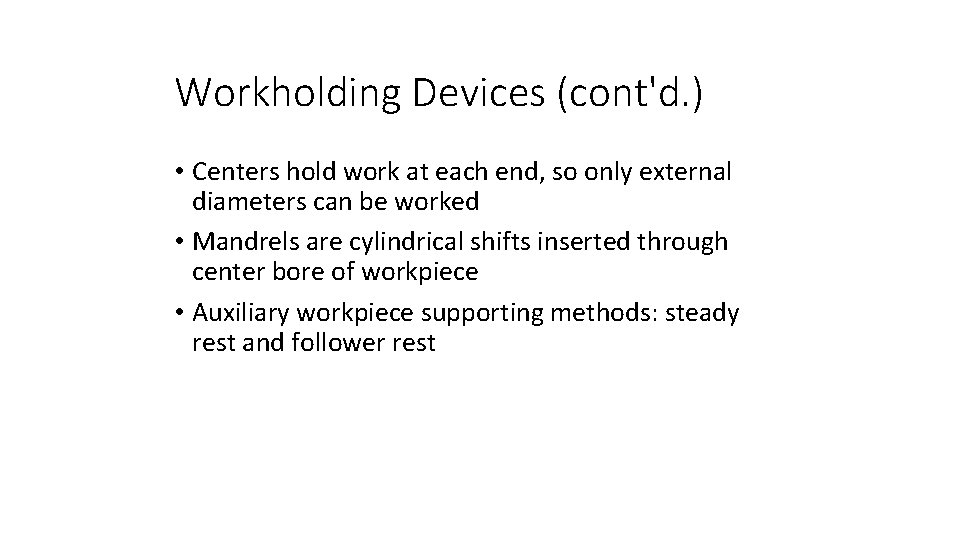
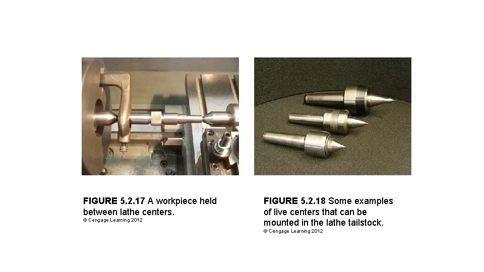
Workholding Devices (cont'd. ) • Centers hold work at each end, so only external diameters can be worked • Mandrels are cylindrical shifts inserted through center bore of workpiece • Auxiliary workpiece supporting methods: steady rest and follower rest
FIGURE 5. 2. 17 A workpiece held between lathe centers. © Cengage Learning 2012 FIGURE 5. 2. 18 Some examples of live centers that can be mounted in the lathe tailstock. © Cengage Learning 2012
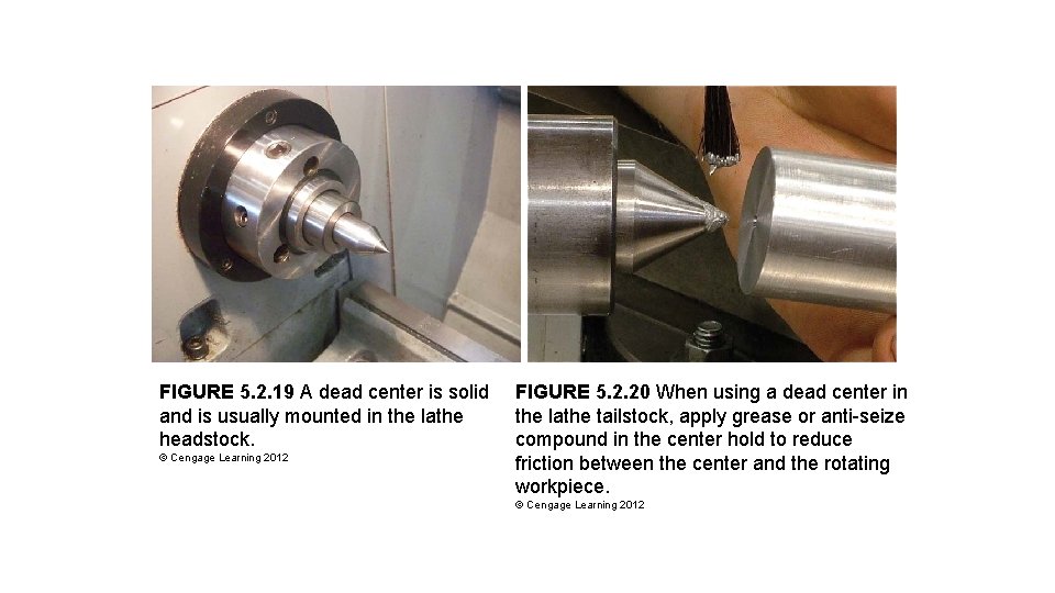
FIGURE 5. 2. 19 A dead center is solid and is usually mounted in the lathe headstock. © Cengage Learning 2012 FIGURE 5. 2. 20 When using a dead center in the lathe tailstock, apply grease or anti-seize compound in the center hold to reduce friction between the center and the rotating workpiece. © Cengage Learning 2012
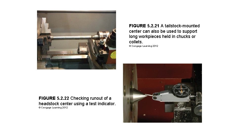
FIGURE 5. 2. 21 A tailstock-mounted center can also be used to support long workpieces held in chucks or collets. © Cengage Learning 2012 FIGURE 5. 2. 22 Checking runout of a headstock center using a test indicator. © Cengage Learning 2012
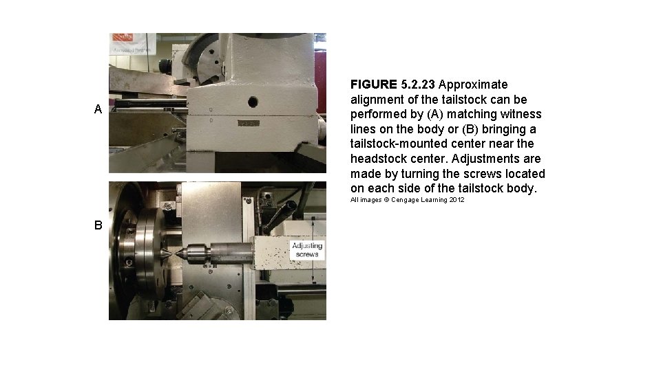
A FIGURE 5. 2. 23 Approximate alignment of the tailstock can be performed by (A) matching witness lines on the body or (B) bringing a tailstock-mounted center near the headstock center. Adjustments are made by turning the screws located on each side of the tailstock body. All images © Cengage Learning 2012 B
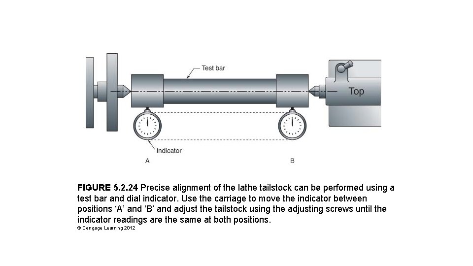
FIGURE 5. 2. 24 Precise alignment of the lathe tailstock can be performed using a test bar and dial indicator. Use the carriage to move the indicator between positions ‘A’ and ‘B’ and adjust the tailstock using the adjusting screws until the indicator readings are the same at both positions. © Cengage Learning 2012
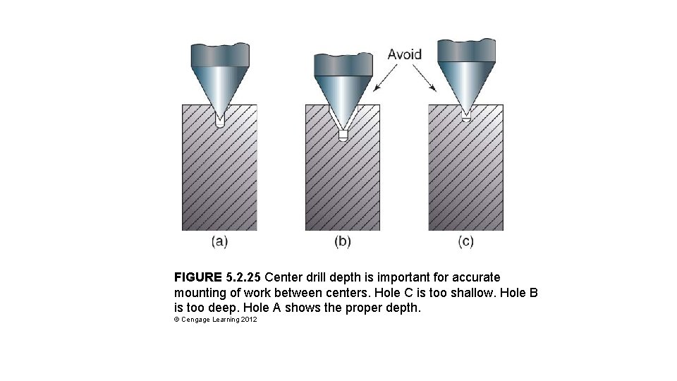
FIGURE 5. 2. 25 Center drill depth is important for accurate mounting of work between centers. Hole C is too shallow. Hole B is too deep. Hole A shows the proper depth. © Cengage Learning 2012
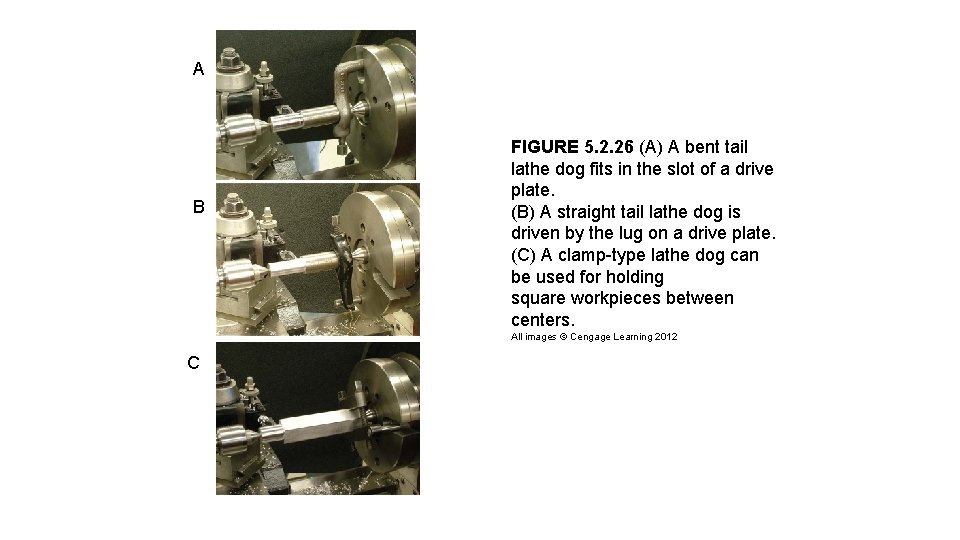
A B FIGURE 5. 2. 26 (A) A bent tail lathe dog fits in the slot of a drive plate. (B) A straight tail lathe dog is driven by the lug on a drive plate. (C) A clamp-type lathe dog can be used for holding square workpieces between centers. All images © Cengage Learning 2012 C
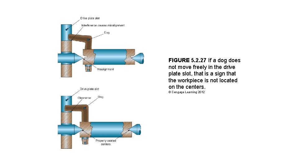
FIGURE 5. 2. 27 If a dog does not move freely in the drive plate slot, that is a sign that the workpiece is not located on the centers. © Cengage Learning 2012
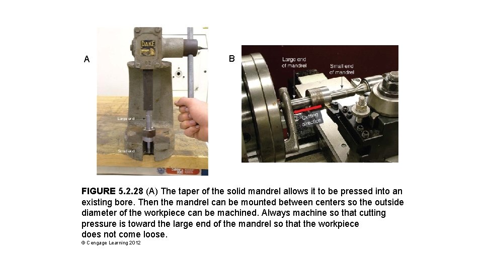
A B FIGURE 5. 2. 28 (A) The taper of the solid mandrel allows it to be pressed into an existing bore. Then the mandrel can be mounted between centers so the outside diameter of the workpiece can be machined. Always machine so that cutting pressure is toward the large end of the mandrel so that the workpiece does not come loose. © Cengage Learning 2012
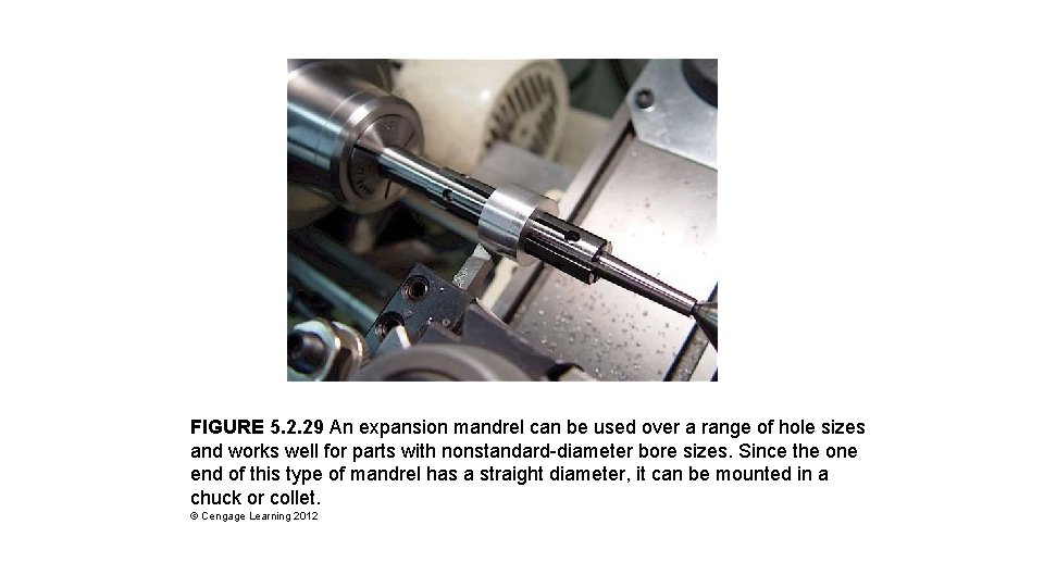
FIGURE 5. 2. 29 An expansion mandrel can be used over a range of hole sizes and works well for parts with nonstandard-diameter bore sizes. Since the one end of this type of mandrel has a straight diameter, it can be mounted in a chuck or collet. © Cengage Learning 2012
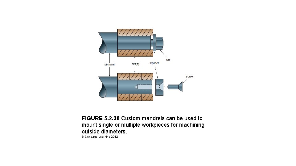
FIGURE 5. 2. 30 Custom mandrels can be used to mount single or multiple workpieces for machining outside diameters. © Cengage Learning 2012
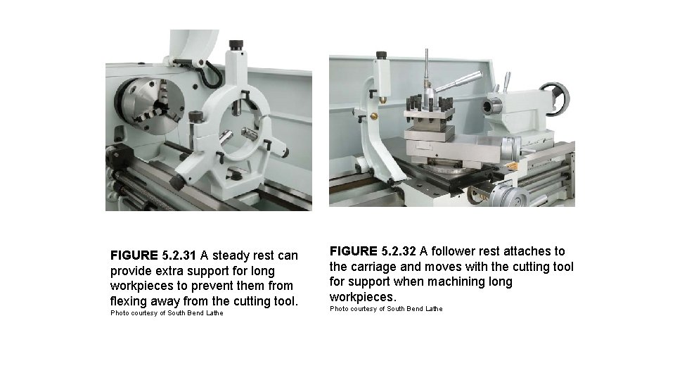
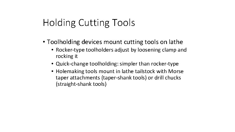
FIGURE 5. 2. 31 A steady rest can provide extra support for long workpieces to prevent them from flexing away from the cutting tool. Photo courtesy of South Bend Lathe FIGURE 5. 2. 32 A follower rest attaches to the carriage and moves with the cutting tool for support when machining long workpieces. Photo courtesy of South Bend Lathe
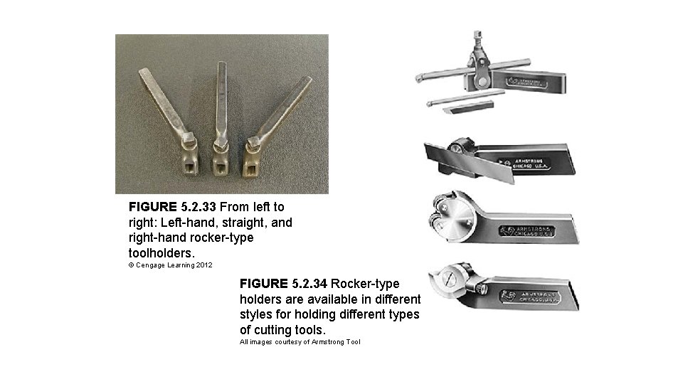
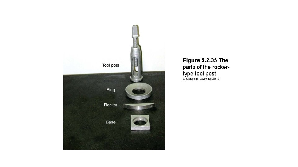
Holding Cutting Tools • Toolholding devices mount cutting tools on lathe • Rocker-type toolholders adjust by loosening clamp and rocking it • Quick-change toolholding: simpler than rocker-type • Holemaking tools mount in lathe tailstock with Morse taper attachments (taper-shank tools) or drill chucks (straight-shank tools)
FIGURE 5. 2. 33 From left to right: Left-hand, straight, and right-hand rocker-type toolholders. © Cengage Learning 2012 FIGURE 5. 2. 34 Rocker-type holders are available in different styles for holding different types of cutting tools. All images courtesy of Armstrong Tool
Figure 5. 2. 35 The parts of the rockertype tool post. © Cengage Learning 2012
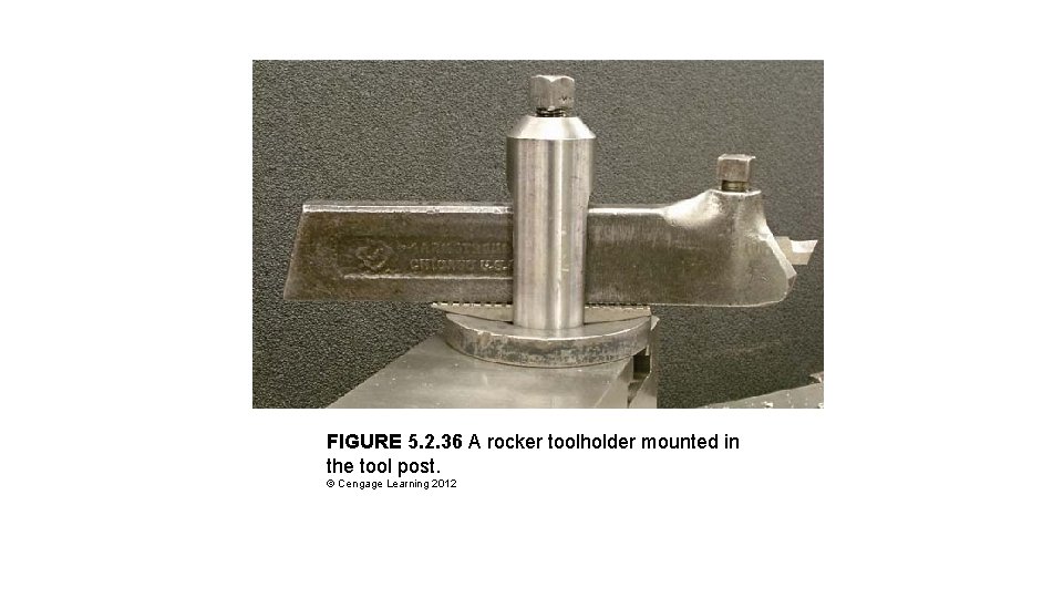
FIGURE 5. 2. 36 A rocker toolholder mounted in the tool post. © Cengage Learning 2012
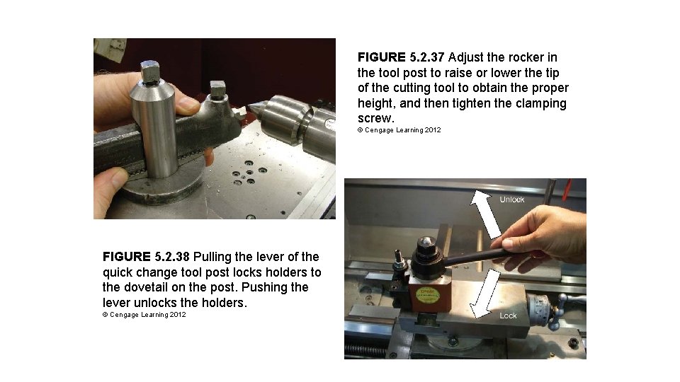
FIGURE 5. 2. 37 Adjust the rocker in the tool post to raise or lower the tip of the cutting tool to obtain the proper height, and then tighten the clamping screw. © Cengage Learning 2012 FIGURE 5. 2. 38 Pulling the lever of the quick change tool post locks holders to the dovetail on the post. Pushing the lever unlocks the holders. © Cengage Learning 2012
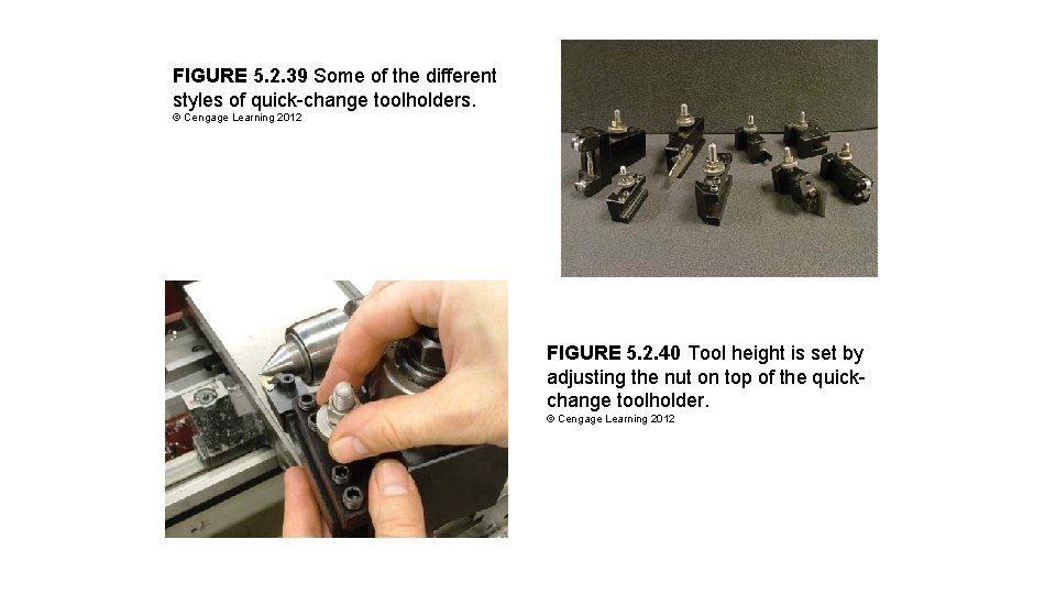
FIGURE 5. 2. 39 Some of the different styles of quick-change toolholders. © Cengage Learning 2012 FIGURE 5. 2. 40 Tool height is set by adjusting the nut on top of the quickchange toolholder. © Cengage Learning 2012
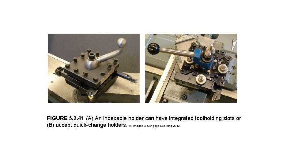
FIGURE 5. 2. 41 (A) An indexable holder can have integrated toolholding slots or (B) accept quick-change holders. All images © Cengage Learning 2012
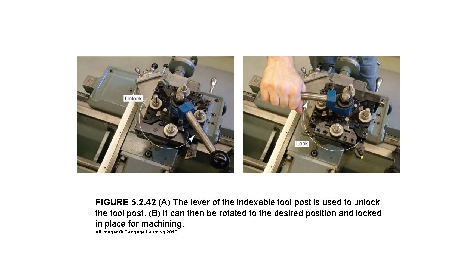
FIGURE 5. 2. 42 (A) The lever of the indexable tool post is used to unlock the tool post. (B) It can then be rotated to the desired position and locked in place for machining. All images © Cengage Learning 2012
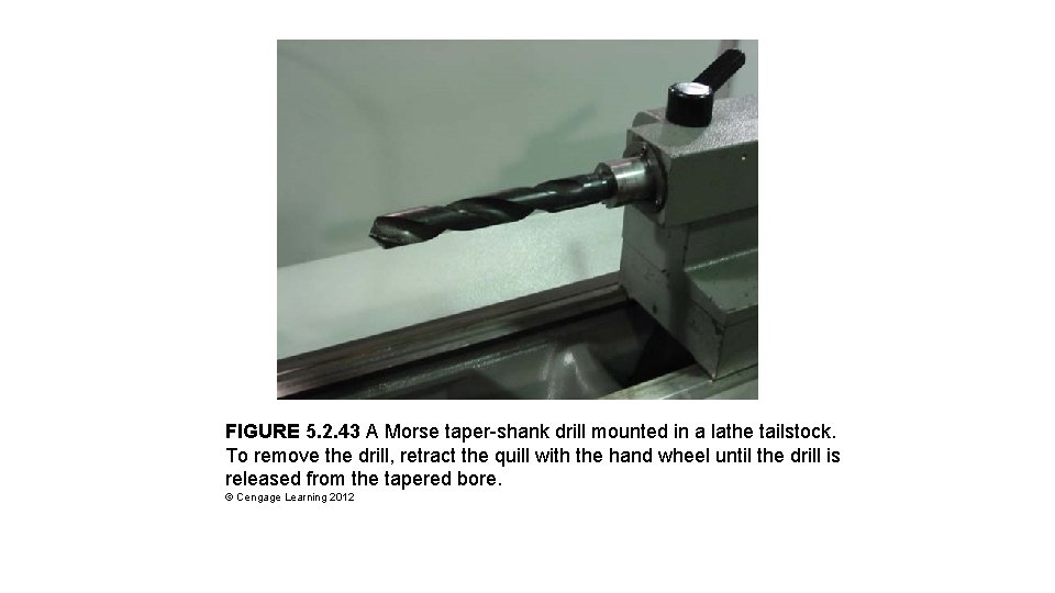
FIGURE 5. 2. 43 A Morse taper-shank drill mounted in a lathe tailstock. To remove the drill, retract the quill with the hand wheel until the drill is released from the tapered bore. © Cengage Learning 2012