Unit 04 1 Machine Elemets Shafts axles keys


 These joints are capable of handling relatively large angular misalignment and")


- Slides: 45
Unit 04 1. Machine Elemets Shafts, axles, keys bearings, flywheel govverner 2. Power transmitting elements Belt drives, chain drives, Gear drives, couplings, clutch, brakes. 3. Mechanisms
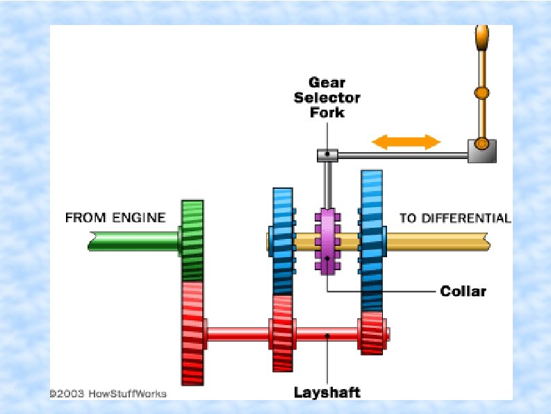
SHAFT
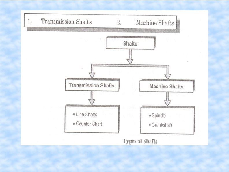
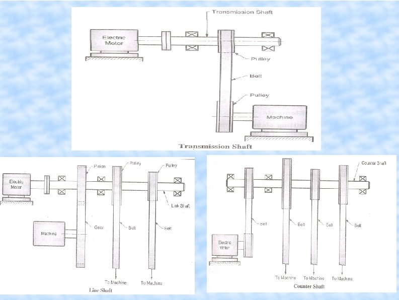
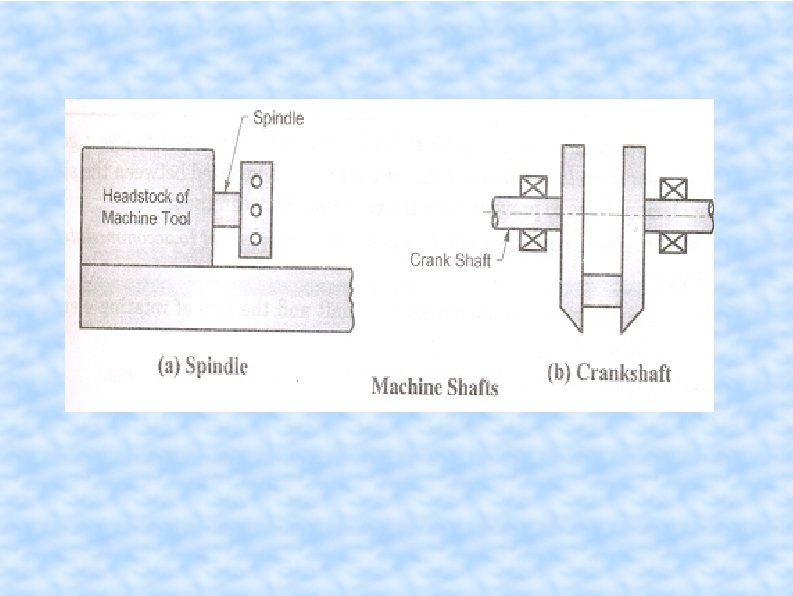
SHAFT In machinery, the general term “shaft” refers to a member, usually of circular cross-section, which supports gears, sprockets, wheels, rotors, etc. , and which is subjected to torsion and to transverse or axial loads acting singly or in combination. An “axle” is a non-rotating member that supports wheels, pulleys, … and carries no torque. A “spindle” is a short shaft. Terms such as line shaft, transmission shaft, counter shaft, and flexible shaft are names associated with special type of shafts.
Elements Attached to a Shaft
Standard sizes of Shafts Typical sizes of solid shaft that are available in the market are, Up to 25 mm 0. 5 mm increments 25 to 50 mm 1. 0 mm increments 50 to 100 mm 2. 0 mm increments 100 to 200 mm 5. 0 mm increments Material for Shafts The ferrous, non-ferrous materials and non metals are used as shaft material depending on the application. Hot-rolled plain carbon steel Cold-drawn plain carbon/alloy composition Alloy steels
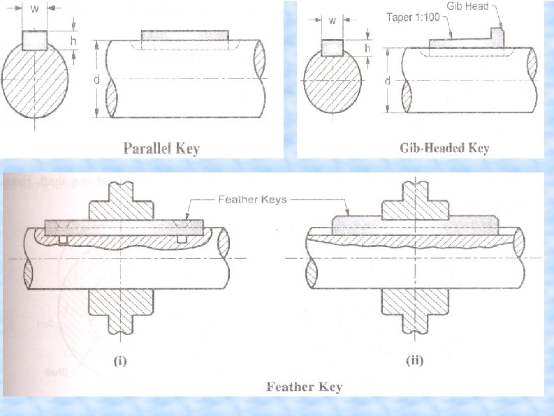
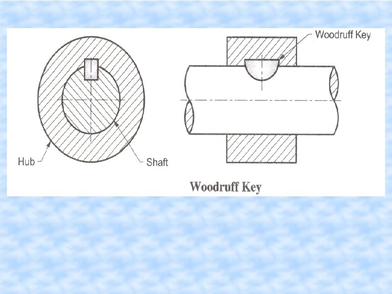
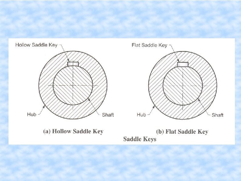
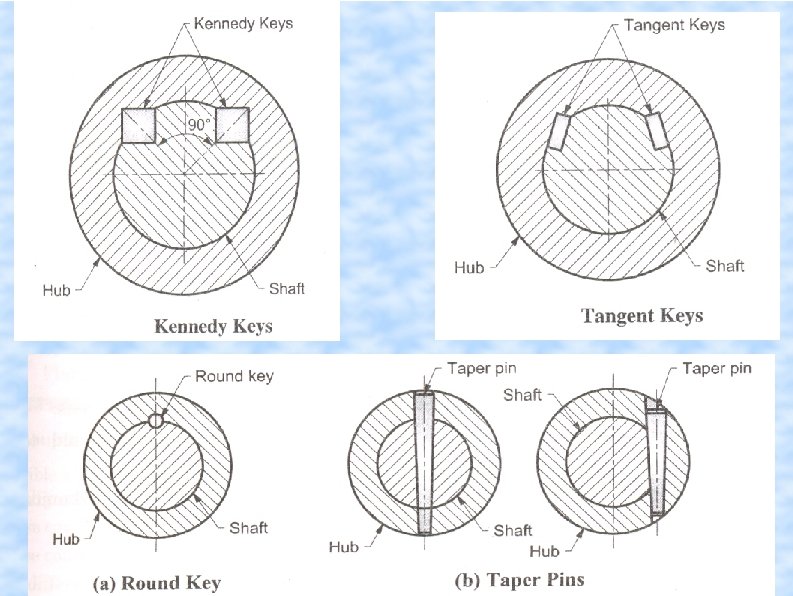
TYPES OF KEYS
Spline
Splines permit axial motion between matching parts, but transmit torque. Common use is automotive drive shafts – check your R/C car
COUPLING Couplings are used to connect two shafts for torque transmission in varied applications. Example-connect two units such as a motor and a generator or it may be to form a long line shaft by connecting shafts of standard lengths say 6 -8 m by couplings.
Couplings In many designs involving shafts, two shafts must be connected co-axially. Couplings are used to make these connections. They may also reduce shock loading and vibration. A wide variety of commercial shaft couplings are available ranging from a simple keyed coupling to one which requires a complex design procedure using gears or fluid drives etc. Couplings are either rigid or flexible. Rigid couplings require very close alignment of the shafts, generally better than. 001” per inch of separation.
main types of couplings: Rigid couplings – It is used for shafts having no misalignment Flexible couplings. It can absorb some amount of misalignment in the shafts to be connected
Rigid couplings • • Sleeve coupling with taper pins Clamp coupling Flange coupling
Types of Misalignment
Rigid Couplings – Sleeves The simplest type of coupling is the simple sleeve coupling. But this also has the lowest torque capacity. One of the simple type of rigid coupling is a sleeve coupling which consists of a cylindrical sleeve keyed to the shafts to be connected.
ADVANTAGES OF MUFF COUPLING : SIMPLE IN CONSTRUCTION NO PROJECTING PARTS REQUIRES LESS RADIAL SPACE DISADVANTAGES OF MUFF COUPLING : DIFFICULT TO ASSEMBLE & DEASSEMBLE CAREFULL FITTING REQUIRED IF THE DEPTH OF KEYWAY IS NOT EXACTLY SAME IN EACH SHAFT, THEN THE KEY WILL BE LOOSE IN ONE SHAFT & BEDDED ON OTHER SHAFT. APPLICATION OF MUFF COUPLING: TO CONNECT TWO LINE SHAFTS.
Split Muff or Clamp Coupling
Flange coupling • It is a very widely used rigid coupling and consists of two flanges keyed to the shafts and bolted
Driving shaft Through key Left side flange Through bolts Right side flange Through key Driven shaft
ADVANTAGES OF FLANGE COUPLING : EASY ASSEMBLING & DEASSEMBLING HIGH TORQUE TRANSMISSION CAPACITY DISADVANTAGES OF FLANGE COUPLING: CANNOT TOLERATE MISALIGNMENT BETWEEN DRIVING & DRIVEN SHAFT REQUIRES MORE RADIAL SPACE APPLICATION OF FLANGE COUPLING : CONNECTING ELECTRIC MOTOR TO PUMP OR COMPRESSER
Flange Coupling
Unprotected Flange Coupling
Flexible Couplings There are many types of flexible couplings as well. Generally something flexible is sandwiched in between, or connected to, rigid flanges attached to each shaft. Alignment is still important! Reaction forces increase with misalignment.
Flexible coupling 1. Pin type flexible coupling 2. Oldham coupling 3. Universal joints
Bushed pin Type Flexible coupling
One of the most commonly used flexible coupling is a pin type flexible flange coupling in which torque is transmitted from one flange to the other through a flexible bush put around the bolt. These are used when excessive misalignment is not expected such as a coupling between a motor and a generator or a pump mounted on a common base plate.
ADVANTAGES OF BUSH-PIN TYPE FLEXIBLE FLANGE COUPLING: CAN TOLERATE SMALL AMOUNT OF LATERAL/ANGULAR MISALIGNMENT. CAN ABSORB SHOCK & VIBRATIONS. HAS HIGH TORQUE TRANSMISSION CAPACITY DISADVANTAGES OF BUSH-PIN TYPE FLEXIBLE FLANGE COUPLING: REQUIRES MORE RADIAL SPACE IT IS COSTLY. APPLICATION OF BUSH-PIN TYPE FLEXIBLE COUPLING : CONNECTING DIESEL ENGINE TO GENERATOR.
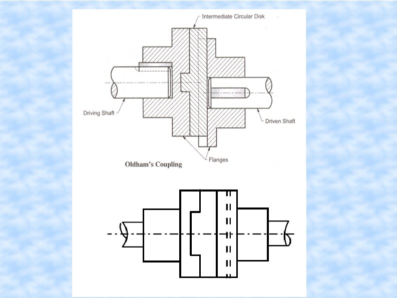
Oldham coupling • These couplings can accommodate both lateral and angular misalignment to some extent. An Oldham coupling consists of two flanges with slots on the faces and the flanges are keyed or screwed to the shafts. A cylindrical disc is placed between the flanges such that the raised portions fit into the slots in the flanges. The disc may be made of flexible materials and this absorbs some misalignment. A schematic representation is shown in figure.
Universal Coupling(Hooke's Joint) These joints are capable of handling relatively large angular misalignment and they are widely used in agricultural machinery, machine tools and automobiles. There are many forms of these couplings, available commercially but they essentially consist of two forks keyed or screwed to the shaft. There is a center piece through which pass two pins with mutually perpendicular axes and they connect the two fork ends such that a large angular misalignment can be accommodated. The coupling, often known as, Hooke’s coupling has no torsional rigidity nor can it accommodate any parallel offset.
ADVANTAGES OF OLDHAM’S FLEXIBLE COUPLING : CAN CONNECT TWO NON-COAXIAL SHAFTS WHOSE AXIS ARE AT A SMALL DISTANCE APART. COMPACT & SIMPLE IN CONSTRUCTION. DISADVANTAGES OF OLDHAM’S COUPLING : THERE ARE POWER LOSSES DUE TO FRICTION & SLIDING MOTION BETWEEN FLANGES & INTERMEDIATE CIRCULAR DISK. CANNOT BE USED FOR HIGH SPEED & HIGH TORQUE APPLICATION’S OF OLDHAM’S COUPLING : CONNECTING TWO ECCENTRIC SHAFTS.
Hooke's Joint
Universal Joints U-joints are considered linkages rather than couplings, but serve the same purpose of transmitting rotation. Very large angular displacements may be accommodated. Single joints are not constant-velocity. Almost always, two joints are used. The angles must be equal for uniform velocity.
ADVANTAGES OF UNIVERSAL COUPLING : CAN CONNECT TWO NON-PARALLEL & INTERSECTING AXES SHAFTS SIMPLE IN CONSTRUCTION. DISADVANTAGES OF UNIVERSAL COUPLING : CANNOT BE USED FOR HIGH SPEED APPLICATION. IN CASE EVEN IF THE DRIVING SHAFT IS ROTATING AT CONSTANT SPEED , THE DRIVEN SHAFT ROTATES WITH ACCELERATION & RETARDATION. THIS GENERATES THE INERTIA TORQUE ON THE DRIVEN SHAFT. APPLICATIONS OF UNIVERSAL COUPLING : AS A COUPLING BETWEEN THE GEARBOX SHAFT & THE DIFFERENTIAL OF AUTOMOBILES. USED TO TRANSMIT THE DRIVES TO DIFFERENT SPINDLES OF MULTI-SPINDLE DRILLING MACHINE.