Undulator based polarized positron source for Circular electronpositron

Undulator based polarized positron source for Circular electron-positron colliders Wei Gai Tsinghua University/ANL The 4 th Beijing-Chicago Workshop, 9/15/2015

Currently, two viable options • CEPC • FCC of CERN • Positron production: conventional approach • What we propose: undulator based approach, use the experience we gained from ILC and CLIC Compton ring.

CEPC lattice layout Critical parameters for CEPC: RF • Circumference: 50 km • SR power: 50 MW/beam • 16*arcs IP 1 RF RF RF • 2*IPs • 8 RF cavity sections (distributed) • 6 straights (for injection and dump) • Filling factor of the ring: ~80% • Revolution time ~ 0. 18 ms RF RF IP 2
 120 10~120 Circumference (Km) 50 50")
Main Parameters Main Collider Booster Energy (Ge. V) 120 10~120 Circumference (Km) 50 50 Bunch Number 50 50 Emittance x/y (nm) 6. 8/0. 02 24/ Life time (min) 30 Beam Current (m. A) 16. 9 0. 84

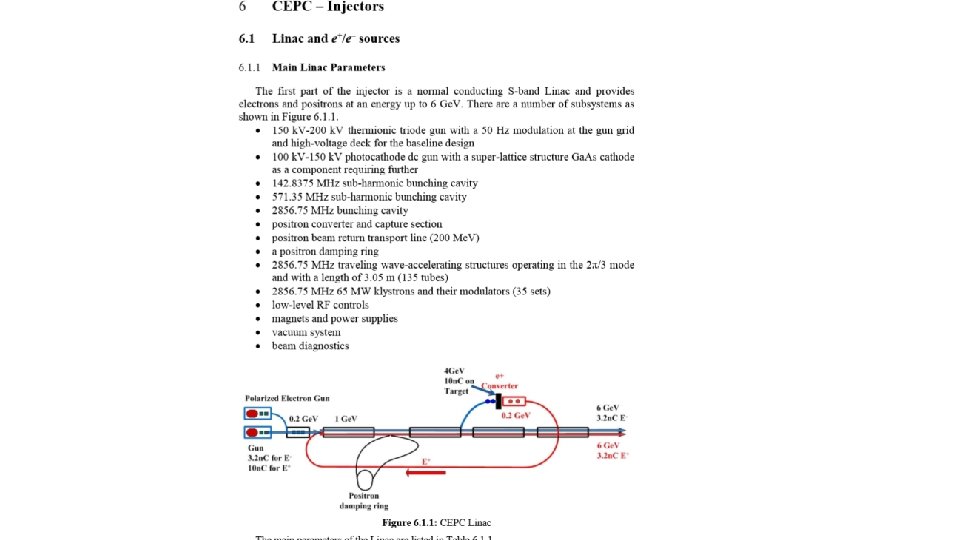
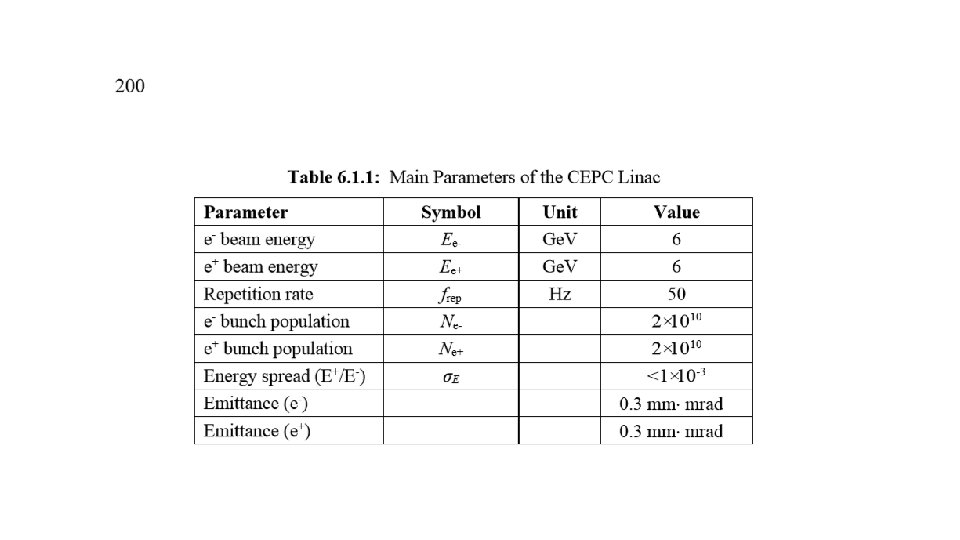
Injection linac • Main parameters Parameter Symbol Unit Value E- beam energy Ee- Ge. V 6 E+ beam energy Ee+ Ge. V 6 Pulse width Δt ns 0. 7 Repetition rate frep Hz 100 E- bunch population Ne- 2× 10¹⁰ E+ bunch population Ne+ 2× 10¹⁰ Energy spread (E+/E-) σE <1× 10 -3 l Challenge 1. Nbunch e+=2 1010 2. Polarization 3. 2 n. C/bunch e+

In general • For 0. 09 m-rad normalized emittance, (9 mm-mrad at 5 Ge. V) the yield would be 1 for 4 Ge. V drive beam. • For 0. 004 m-rad as required by, CEPC, the estimated yield would be ~ 0. 1 (much less than 1). • Drive beam needs to be

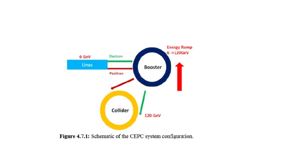
Is there an alternative solution? • Based the ILC and CLIC studies, a combination of the undulator based and Compton ring based scheme could produce polarized positron while simplifying the CEPC overall configuration.

Injection Options Geometrical Arrangement Booster 2 m Main Collider

~ 50 km of main ring and booster Overall layout of the Concept. Simpler than ILC and CLIC, much less demand Injection into booster ring at 6 Ge. V, (Tang made direction right) Stacking as in CLIC design and with some damping 4 meter Helical undulators Either in booster or Main ring Target, capturing for positron and acceleration 6 Ge. V for both electron and positron

ILC TDR positron source location Target for e+ 147 m helical undulator production Optical Matching for photon production Device for e+ capture Photon collimator PCAP for pol. upgrade Main e- beam from electron main linac PPA (125 -400 Me. V) PBSTR 400 Me. V -5 Ge. V Damping ring g PTAPA (~125 Me. V) g dump e- dump Main e- beam to IP PLTR: Energy compression and spin rotation 150 Ge. V beam to dump 13
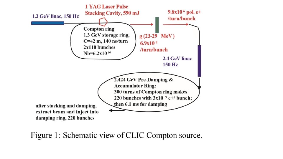

OK, what to do next? • • • Insert a small section of undulator as ILC, but much smaller. 120 Ge. V electron would produce 3 photons/meter 1 good e+/100 photons 4 meters undulator (loss 50 – 100 Me. V/turn) Use Compton stacking (50 turns) Production 50 (turns) x 50 (bunches) = 6 ms • Or can be re-arranged in many different configurations

Comparing with ILC and CLIC • Timing made easy with the ring scheme. • The booster only operate a part time (a few sec for every 30 mins) • Target stress level is much less than ILC, no major issues here. • Polarization can be as high as ~ 80% (even higher? ). • Overall optimization paradigm can be drastically different, probably CEPC is much easier

RDR undulator based positron source • • • Undulator parameter: K=0. 9, lu=1. 15 cm Length of undulator: 231 m long Target: 0. 4 X 0 Ti Drift between undulator and target: 400 m Photon collimator: None Optical matching device: ¼ wave transformer i lu -i

Photon number spectrum and distribution functions • The spectrum of photon generated by helical undulator is known as: (1) Photon number spectrum in terms of harmonics (2) Harmonics distribution function (3) Energy distribution function (4) 18

ILC RDR undulator photon number spectrum

Yield contribution from different harmonics 231 m RDR undulator , 150 Ge. V drive beam, 400 m drift from the end of undulator to target In CEPC case, it would be more of 1 st harmonic dominated. 20

Yield and polarization of RDR configuration for different drive beam energy Drive beam energy Energy lost per 100 m Energy lost for 1. 5 yield 50 Ge. V ~225 Me. V N/A 100 Ge. V ~900 Me. V ~9. 9 Ge. V 150 Ge. V ~2 Ge. V ~4. 6 Ge. V 200 Ge. V ~3. 6 Ge. V ~3. 7 Ge. V 250 Ge. V ~5. 6 Ge. V ~3. 96 Ge. V Drive beam energy Yield Polarizatio n 50 Ge. V 0. 0041 0. 403 100 Ge. V 0. 3138 0. 373 150 Ge. V 1. 572 0. 314 200 Ge. V 3. 298 0. 265 250 Ge. V 4. 898 0. 221 21

Polarization upgrade 231 m RDR undulator, 150 Ge. V drive beam, ¼ wave transformer With QWT, with a photon collimator to upgrade the polarization to 60%, the positron yield will drop to ~0. 8 Drive beam energy Energy lost per 100 m Energy lost for 1. 5 yield and 60% polarization 150 Ge. V ~2 Ge. V ~8. 8 Ge. V 22

CEPC alternative e+ source -- Yield and Polarization The results showing that in order to achieve yield of 1 by stacking 50 e+ bunches together, the K needs to be 0. 9. The associated polarization will be about 33%

• What possible differences are at CEPC: Lower K: less photons, better polarizations. Target is much less likely be damaged and conventional facilities are much easier. Possible no remote handling is needed. No need for a drive beam generation. Much lower cost than ILC and CLIC. A 6 Ge. V linac for both electron and positron sources. Techs developed for ILC and CLIC are readily adapted to CEPC. 24

CEPC alternative e+ source -- Yield and Polarization The results showing that in order to achieve yield of 1 by stacking 50 e+ bunches together, the K needs to be 0. 9. The associated polarization will be about 33%

Conversion yield at target for 50 Ge. V Drive Beam Target conversion yield for 50 Ge. V drive beam shows that K of about 0. 9 and target thickness of 0. 2 X 0 is preferred for higher yield

Conversion yield at target for 70 Ge. V Drive Beam Target conversion yield for 70 Ge. V drive beam shows that K of about 0. 9 and target thickness of 0. 15 X 0 is preferred for higher yield

Captured yield and pol when drive beam is at 70 Ge. V Using k=0. 9, lu=1. 15, with 70 Ge. V drive beam, the captured e+ yield can be above 9 e-4 for 4 m long undulator and a single stacking. The polarization at the highest yield is about 33%. If we give up about 20% on the yield, the polarization will be doubled to above 60%.

Captured yield and pol when drive beam is at 50 Ge. V The polarization of captured beam doesn’t follow the same trend as for other drive beam energy. More detailed investigation is needed.

What if I were…. . All the works below are not challenging, but tedious. • Good understanding of the timing, timing and timing • Study the effect of low K on polarization and yield, capturing. Perform end to end simulations. • Re-examine the CLIC stacking/pre damping ring. • Injection into the booster and spin de-polarizations. • Total power consumption estimations. 30
- Slides: 30