UMTS Universal Mobile Telecommunications System Aim of Presentation

UMTS: Universal Mobile Telecommunications System

Aim of Presentation n n n To attain a general understanding of UMTS systems GSM Evolution Towards UMTS 2. 5 G Standards (Transition between 2 G-3 G) Difference between GSM-UMTS: FDD/TDD UMTS Network Elements and Architecture UE: User Equipments UTRAN: UMTS Terrestrial Radio Accesses Network CN: Core Network n n Major Interfaces in UMTS Introduction to 3 G Planning Techniques

UMTS: A Brief Overview n n UMTS is the recent telecomm Standard system (3 G) developed from the existing GSM system, one can say that its a resultant of R&D done on various levels of 1 st and 2 nd generation GSM system It is a universal Mobile telecom system designed to provide seamless telecomm services with enhancement in quality, data, rate, reliability, connectivity , system interfaces adaptability , current and next generation technologies …and so on

n n n UMTS is a 3 G GSM successor standard i. e. downward-compatible with GSM, UMTS is the third generation solution developed and adopted by ETSI (European Technical Standards Institute). It is therefore expected that the vast majority of current GSM operators will become involved in deploying UMTS networks

GSM Evolution Towards UMTS Evolution of GSM towards UMTS can be explained in terms of “generations”: The entire cellular systems since intoduced has effectively been replaced at times. These major changes are referred to as a new “generation” of cellular systems.

2. 5 G Standard A Transition 2 G-3 G HSCS n n n High Speed Circuit Switched Data Enhancement to the GSM standard Utilises: Multiple channel coding schemes (4. 8 kbps, 9. 6 kbps, 14. 4 kbps per timeslot) Multiple timeslots Circuit Switched Data rates to 57. 6 kbps 4 slots with 14. 4 kbps channel coding per slot

GPRS n n n General Packet Radio Service Enhancement to the GSM standard Utlilises Multiple Timeslots Packet Switching n Packet Switched Data typically to rates of 56 kbps Theoretically 171. 2 kbps for 8 timeslots n UMTS Introduces serving GPRS support node SGSN
 n n")
EDGE n Enhanced Data for GSM Evolution Sometimes called E-GPRS (Enhanced GPRS) n n Enhancement to the GSM and TDMA standards Utlilises: 8 PSK Modulation Possible 1. 6 MHz carrier under IS-136 8 Channel Coding Schemes Multiple Timeslots (similar frame structure to GSM) TDMA n Data up to rates of 384 kbps (typically less)

Difference GSM and UMTS Major difference is air interface – GSM: TDMA and FDMA – UMTS: Wide-band code division multiple access (WCDMA)

UMTS Modes UMTS-FDD UMTS-TDD

UMTS FDD • Universal Mobile Telecommunications System Frequency Division Duplexing Mode • Built onto enhanced GSM core network • Utilises: • QPSK modulation (Quadrature phase shift keying) • Multiple channel coding and bearer rates • Variable spreading factors and multi-code transmission • CDMA • FDD • Asynchronous operation • Data up to rates of 2 Mbps

UMTS TDD • Universal Mobile Telecommunications System Time Division Duplexing Mode • Built onto enhanced GSM core network • Utilises: • QPSK modulation • Multiple channel coding and bearer rates • CDMA • TDD • Asynchronous operation • Data up to rates of 2 Mbps • Will happen after UMTS FDD

UMTS Architecture Overview
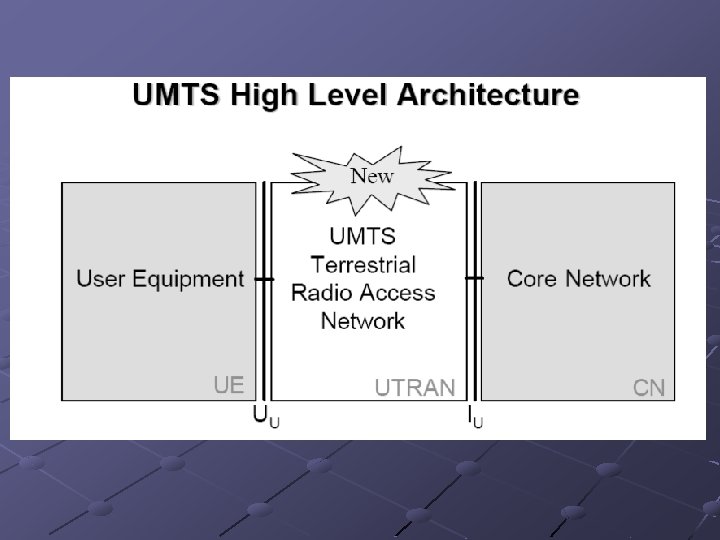


User Equipment UE The UMTS UE is based on the same principles as the GSM MS— the separation between mobile equipment (ME) and the UMTS subscriber identity module (SIM)card (USIM). UE consists of : · Display and User Interface · Holds the Authentication Algorithms and keys · User End Termination of the Air Interface · Application Platform

Mobile Equipment The radio terminal is used for radio communication over the Uu interface UMTS Subscriber Identity Module The smartcard that holds the subscriber identity, authentication and encryption keys Etc Terminal Equipment The terminal equipment connects to the UE. This carries the application specific user interface
 The database storing the master copy")
General Core Network Architecture Home Location Register (HLR) The database storing the master copy of a users profile Visitor Location Register (VLR) The database holding a copy of a visiting users profile Mobile Switching Centre (MSC) Switch for Circuit Switched Services Gateway MSC (GMSC) Serving GPRS Support Node (SGSN) Router for Packet Switched Services Gateway GPRS Support Node (GGSN)

UMTS Terrestrial Radio Access Network UTRAN Node B Acts as the radio basestation (BTS in GSM) Converts the data flow between the Iub and Uu interfaces RNC • Responsible for the use and integrity of the radio resources within the RNS • Responsible for the handover decisions that require signalling to the UE • Provides a combining/splitting function to support macrodiversity between different Node Bs

Major Interfaces in UMTS • There are four major new interfaces defined in UMTS • Iu The interface between UTRAN and the CN • Iur The Interface between different RNCs • Iub The interface between the Node B and the RNC • Uu The air interface

Radio Planning for UMTS n Principle Design Considerations There are two design considerations when planning a 3 G network. 3 G is a multiservice network and 3 g requires the practical implementation of WCDMA

Planning can be broken into 3 phases Dimensioning: To determine the approximate number of sites, cells and number of network elements. · Radio Link Budget · Coverage Analysis · Capacity estimation · Required numbers of network elements eg RNC’s Detailed planning: Involves the use of a radio network planning tool. Ericcson - TEMS Cell planner · ATDI - ICS Telecom System · Logica - Odyssey · Nokia – Net. Act Planner · CRIL - ELLIPSE M-NPT Optimisation: In WCDMA system optimisation starts right back at the planning phase

n n Interference is the biggest problem in WCDMA and need to control, this can be done through Optimisation of Site Location and configuration Height, direction, beamwidth and tilt of antennas Cable losses Mast head amplifiers

- Slides: 24