UML Diagrams Sequence Diagrams The Requirements Model and


")

")
")


")


- Slides: 58
UML Diagrams: Sequence Diagrams The Requirements Model, and The Dynamic Analysis Model Instructor: Dr. Hany H. Ammar Dept. of Computer Science and Electrical Engineering, WVU
Outline n n n n n Review of previous Lecture The Requirements Model and the Analysis model Importance of Sequence Diagrams Rules of sequence diagrams Use Cases and Sequence Diagrams The System Sequence Diagrams The Sound Recorder Example The E-Commerce Example Other Examples
Review of Previous lecture n n n Review of development phases and UML Development - Overview Introduction and importance of Use Case Diagrams Use Case Diagram Rules Examples of Use Case diagrams Requirements Elicitation Process 1. Identify Actors 2. Identify Scenarios 3. Identify Use Cases 4. Refine Use Cases 5. Identify Relationships between actors and Use Cases 6. Identify Initial Analysis Objects 7. Identify Non-functional requirements
Requirements, Use cases, and Scenarios
UML Development - Overview ACTORS REQUIREMENTS ELICITATION SCENARIOS Requirements Engineering ANALYSIS Specify Domain Objects USE CASES ANALYSIS CLASS DIAGRAM(S) Time System/Object SEQUENCE DIAG. State. Chart DIAGRAMs OPERATION CONTRACTS Architectural Design SUBSYSTEM CLASS/ Include OR COMPONENT Design Objects DIAGRAMS DEPLOYMENT DIAGRAM DESIGN DIAGRAMS Detailed DESIGN Object Design IMPLEMENTATION CHOICES IMPLEMENTATION DESIGN SEQUENCE DIAG. IMPLEMENTATION Activity DIAGRAMS PROGRAM D A T A D I C T I O N A R Y
Where are we in the Requirements Engineering ? n Requirements Engineering focus: elicitation and analysis
The Requirements Model and the Analysis Model The Requirements Elicitation Process Functional/ Nonfunctional Requirements Use Case Diagrams/ Sequence Diagrams (the system level) The Object-Oriented Static Analysis - Class Diagrams Analysis Dynamic Analysis - State Diagrams/ Process Refined Sequence Diagrams (The object level)
Outline n n n n n The Requirements Model and the Analysis model Introduction to Requirements Engineering Importance of Sequence Diagrams Rules of sequence diagrams Use Cases and Sequence Diagrams The System Sequence Diagrams The Sound Recorder Example The E-Commerce Example Other Examples
Importance of Sequence Diagrams Depict object interactions in a given scenario identified for a given Use Case n Specify the messages passed between objects using horizontal arrows including messages to/from external actors n Time increases from Top to bottom n
Rules of Sequence Diagrams n Sequence Initiation
Rules of Sequence Diagrams n n n Identify objects needed to support use cases, determine sequence of internal events following the external initiating event Diagrams that are not initiated with an external actor represent only a partial sequence Partial sequence diagrams should clearly identify the actor initiated sequence diagrams from which they are launched
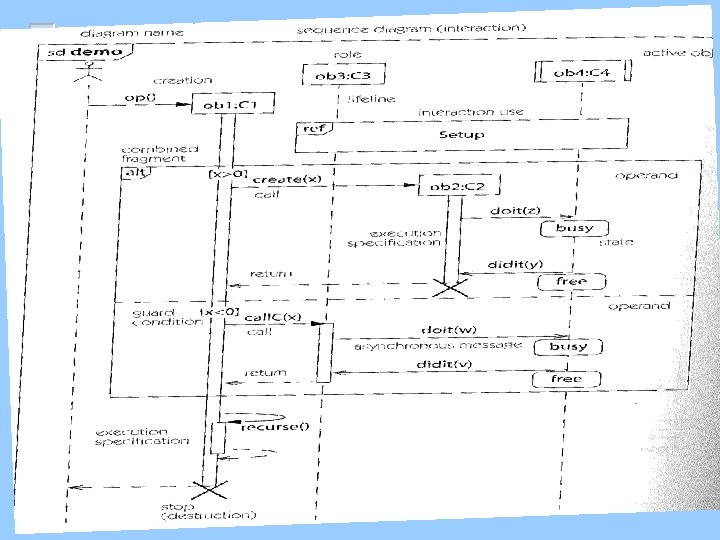
Example of Sequence Diagrams Notation
Rules of Sequence Diagrams n Messages specified on interactions can be synchronous or asynchronous Synchronous call
Rules of Sequence Diagrams Asynchronous call
Rules of Sequence Diagrams n Display operation names on call arrows
Rules of Sequence Diagrams Compound and Simple Iteration
Numbering the Sequence of Interactions
‘included’ sequence diagrams
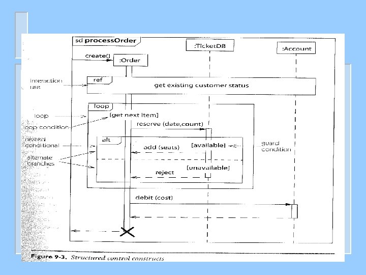
Showing alternate behavior in a sequence diagram
Showing Extension Point
Rules of Sequence Diagrams Showing alternate behavior in a sequence diagram
Communication/Collaboration Diagrams They Specify similar information of interactions without the time axis
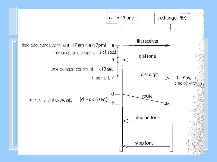
Specifying Timing Requirements
Specifying Timing Requirements
Specifying Timing Requirements (Data rates in notes)
Specifying Timing Requirements: on interactions
Specifying Timing Requirements (ave and max)
Specifying Timing Requirements: (Timeout events)
Outline n n n n n The Requirements Model and the Analysis model Introduction to Requirements Engineering Importance of Sequence Diagrams Rules of sequence diagrams Use Cases and Sequence Diagrams The System Sequence Diagrams The Sound Recorder Example The E-Commerce Example Other Examples
Recall Requirements Elicitation Process n The process of requirements elicitation consists of the following steps 1. 2. 3. 4. 5. 6. 7. Identify Actors Identify Scenarios Identify Use Cases Refine Use Cases Identify Relationships between actors and Use Cases Identify Initial Analysis Objects Identify Non-functional requirements
Requirements Elicitation Process Step 4. Refining Use Cases System Sequence Diagrams n n n System sequence diagrams establish the dynamic behavior in terms of key scenarios of the system for each use case The system sequence diagram models a scenario of the system interactions with the environment for a given use case Input/output events are clearly identified in each sequence diagram, The State of the system before and after each event are also depicted Different diagrams model scenarios with the normal flow of events and the abnormal flow of events
Sequence Diagrams and Use Cases System Sequence Diagram The use case diagram Of system S The sequence diagram of use case UC 1 for system S
UML Use Case Diagrams: The Requirements Model Case Study
UML Use Case Diagrams: The Requirements Model- System Seq. Diags. Digital Sound Recorder Case Study n A sequence diagram displays object interactions arranged in a time sequence capturing a specific scenario of interactions in a use case supported by the system Sequence Diagram for Play Massage Scenario: Normal Flow Time
Sys. Seq. Diagram for Alarm sounding while playing Massage Scenario
Sys. Seq. Diag. for Alarm while stand-by followed by No-power event.
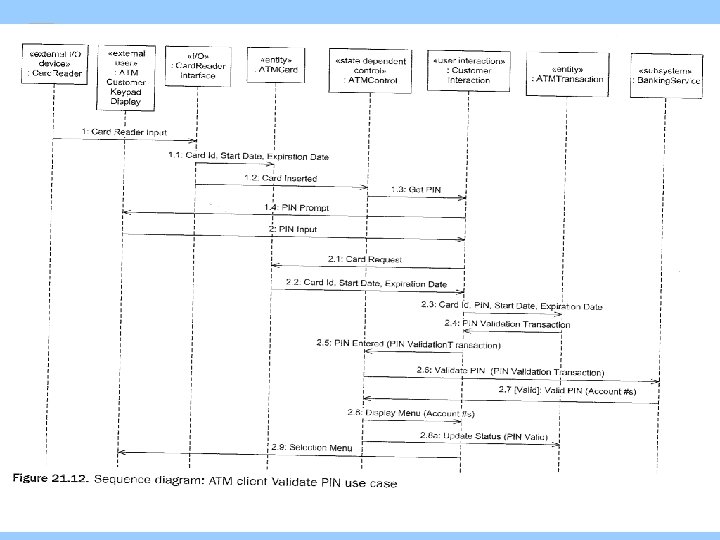
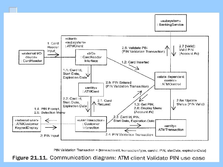
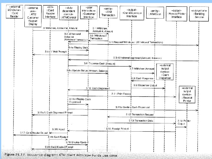
The ATM Example
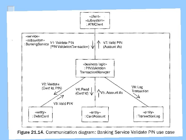
This is for the Banking Service Subsystem
Example: Use Case Diagram of the E-Commerce System
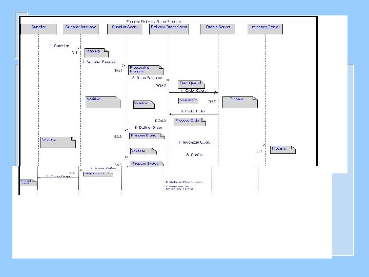
Place Requisition Scenario
Confirm Delivery Scenario
Send Invoice Scenario
Confirm Shipment Scenario
Another Example: Pace Maker Use-Case model
Pace Maker Sys. Seq. Diag
Seq. Diag. at the object level (The Analysis Model)
A Simple Example of Using UML 2 n EXAMPLE: SATELLITE CONTROL SYSTEM
Example of Software Architecture Using UML 2 n SATELLITE CONTROL SYSTEM Architecture
A Simple Example Using UML 2 n SATELLITE CONTROL SYSTEM Architectural behavior