
UML 3 Notations describe how to use reusable
UML 3 Notations describe how to use reusable software. Package Component Deployment Node UML 3 © Wolfgang Pelz 2000 -04 1
Package Diagram • general purpose grouping mechanism to organize semantically related model elements • can be considered a special case of a class diagram • define a namespace or context (container) within which each name must be unique UML 3 © Wolfgang Pelz 2000 -04 2
Package Diagram • can be nested (implied import of parent) • may hide their contents UML 3 © Wolfgang Pelz 2000 -04 3
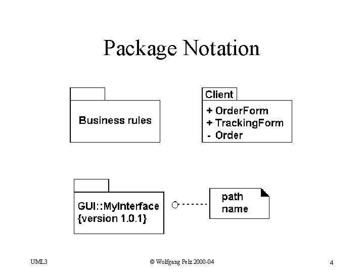
Package Notation UML 3 © Wolfgang Pelz 2000 -04 4
Properties • a package may own other elements, including classes, interfaces, components, nodes, collaborations, use cases, diagrams, and other packages • ownership is a composite relationship - if the enclosing package is destroyed, then the enclosed elements are also destroyed UML 3 © Wolfgang Pelz 2000 -04 5
Visibility specifiers: • public - element is visible to a package that imports the element’s enclosing package • protected - element is visible to a package that inherits from another package • private - element is not visible outside the package UML 3 © Wolfgang Pelz 2000 -04 6
More visibility • public parts of a package constitute the package’s interface • friend dependency relationship: two packages that are friends may see all elements in the packages, independent of visibility UML 3 © Wolfgang Pelz 2000 -04 7
Usage • model an import relationship with the stereotype import on the dependency • stereotype access permits usage without adding contents to namespace; requires fully qualified name • public parts of package are called its exports UML 3 © Wolfgang Pelz 2000 -04 8
Standard Stereotypes • facade: package is a view on another package • framework: package consists of patterns • stub: proxy for public contents of another package • subsystem: independent part of the entire system being modeled • system: represents entire system being modeled UML 3 © Wolfgang Pelz 2000 -04 9
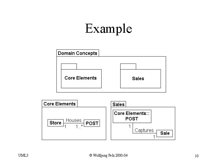
Example UML 3 © Wolfgang Pelz 2000 -04 10
Package Dependency • elements of the dependent package know about or are coupled to elements in the target package • a dependency between two packages exists if there is a dependency between any two classes in those packages • dependencies are not transitive • rule of thumb: reduce # of dependencies (why? ) UML 3 © Wolfgang Pelz 2000 -04 11
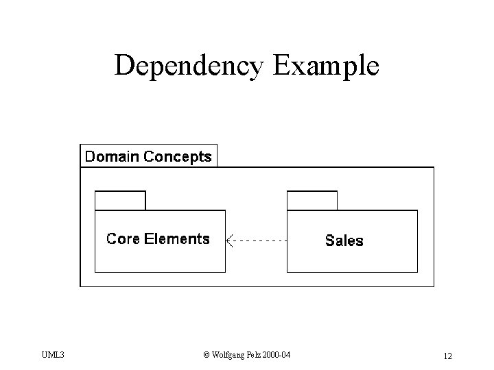
Dependency Example UML 3 © Wolfgang Pelz 2000 -04 12
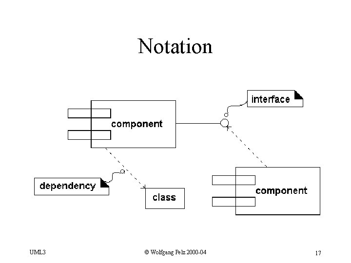
Component Diagram • a component represents the physical packaging of related elements such as classes, interfaces, and collaborations • defined as “a reusable part that provides the physical packaging of a collection of model element instances” • typically a component is an implementation file in the development environment UML 3 © Wolfgang Pelz 2000 -04 13
Software Component • source component: source code implementing one or more classes; meaningful at compile-time • binary component: object code that is a result of compiling a source component, e. g. , object code file, static library file, or dynamic library file UML 3 © Wolfgang Pelz 2000 -04 14
Software Component • Executable component: executable program that is the result of linking all binary components UML 3 © Wolfgang Pelz 2000 -04 15
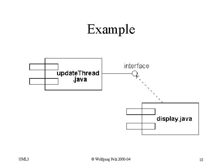
Component • is physical: lives in the world of bits, not concepts • is replaceable or substitutable • is part of a system; does not stand alone • conforms to and provides the realization of a set of interfaces UML 3 © Wolfgang Pelz 2000 -04 16
Notation UML 3 © Wolfgang Pelz 2000 -04 17
Example UML 3 © Wolfgang Pelz 2000 -04 18
Another Example UML 3 © Wolfgang Pelz 2000 -04 19
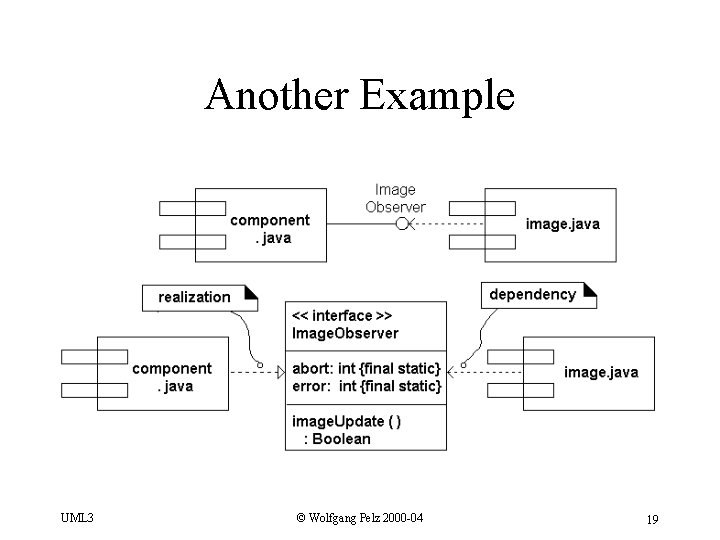
Understanding the Example • Realization: inheritance, class relationship, one class is part of the definition of the other. • Dependency: uses, object relationship, one object uses another object. – Inclusion: one object is part of the other object – Call: one object calls a method of the other UML 3 © Wolfgang Pelz 2000 -04 20
Deployment Diagram • shows physical relationships among software and hardware components • each node represents some kind of computational resource, usually a piece of hardware (e. g. , computer, printer, card reader, sensor) • a node exists at run-time UML 3 © Wolfgang Pelz 2000 -04 21
Architecture • see which components are executing in a node • see which logical elements (classes, objects, collaborations, etc. ) are implemented in the component • be able to trace the element to the initial requirement analysis of the system (typically through the use case diagram) UML 3 © Wolfgang Pelz 2000 -04 22
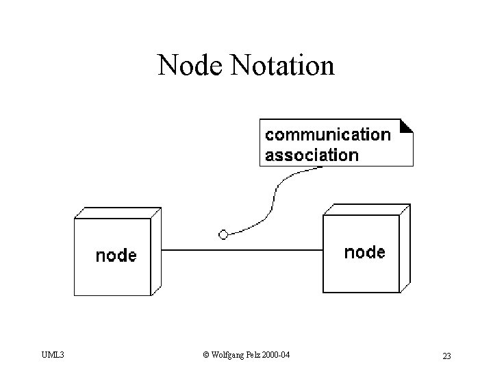
Node Notation UML 3 © Wolfgang Pelz 2000 -04 23
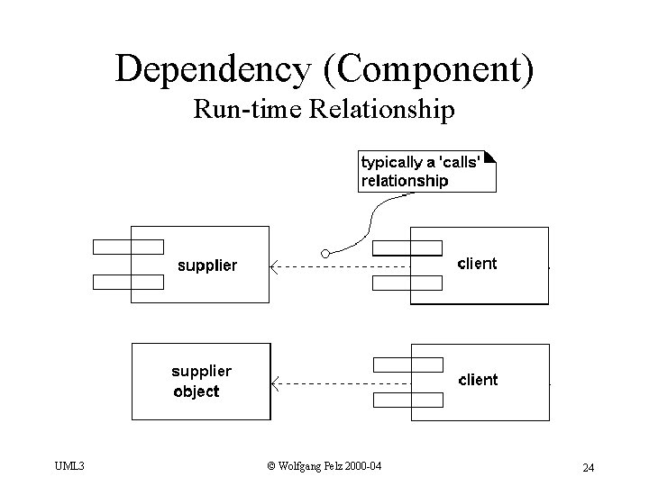
Dependency (Component) Run-time Relationship UML 3 © Wolfgang Pelz 2000 -04 24
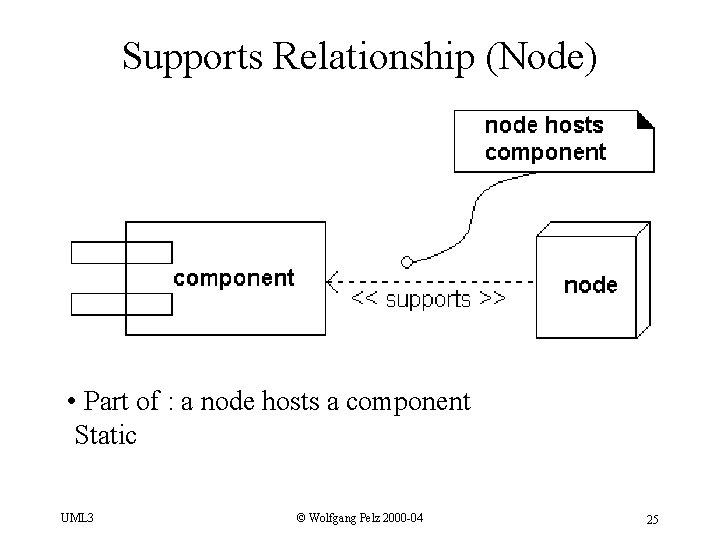
Supports Relationship (Node) • Part of : a node hosts a component Static UML 3 © Wolfgang Pelz 2000 -04 25
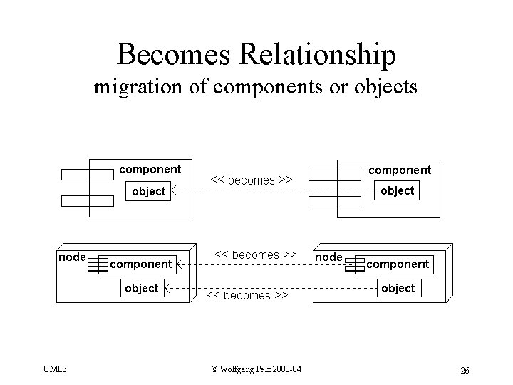
Becomes Relationship migration of components or objects UML 3 © Wolfgang Pelz 2000 -04 26
Becomes Relationship migration of components or objects • The directory (object) /home/vonneumann/faculty/xiao • on Samba Server (node) • becomes • “z: ” drive (object) on my laptop (node) UML 3 © Wolfgang Pelz 2000 -04 27
- Slides: 27