Typical Microcomputer Architecture register incoming Lab Bus subsystem

Typical Microcomputer Architecture register incoming Lab.

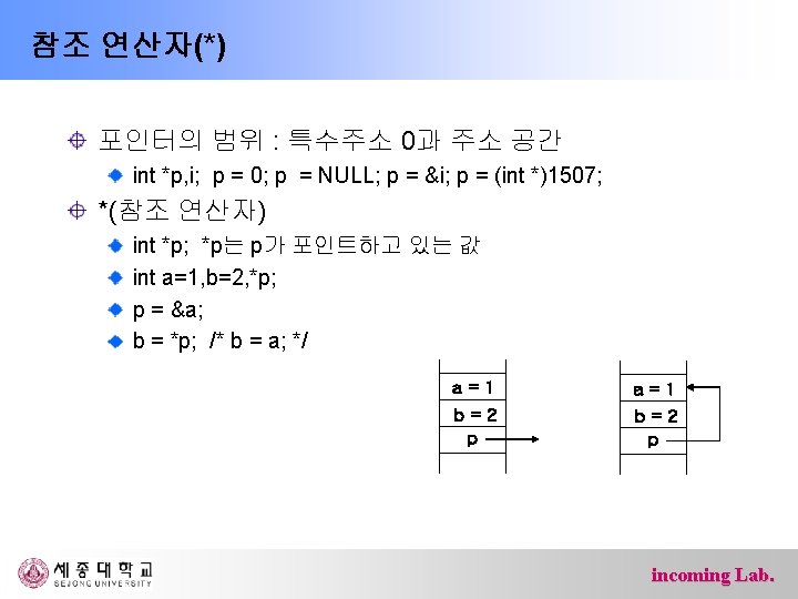
Bus subsystem that transfers data between computer components address lines : used to specify a physical address Ø N address lines => 2 N addresses Ø address space : total number of available addresses data lines : a path where data is transferred Ø number of data lines => typical data unit, word Ø ATmega 128 : 8 bit Ø Intel Pentium : 64 bit control lines : identify the nature (read, write, …) of the bus incoming Lab.

Memory devices that are used to store data or programs on a temporary or permanent basis for use in a computer volatile requires power to maintain the stored information RAM (Random-Access Memory) Ø SRAM, DRAM, … nonvolatile can retain the stored information even when not powered ROM (Read-Only Memory) Ø PROM, EEPROM, … Ø hard disk, optical disk, … Ø flash memory Ø … incoming Lab.
 size of memory")
Memory organized as a linear array of cells (smallest addressable unit) size of memory address lines : number of cells data lines : number of bits in cells Ex) Ø 24 address line & 8 bit data line – 224 x 8 bit = 16 mega bytes Ø 1 giga bytes – 1 giga = 230 => address lines : 30, data lines : 8 Ø 2 GB memory (64 bit machine) – 2 GB=2* 230 * 8 bits = 228 * 8*8 – address lines : 28, data line : 64 – 256 MB*8 or 128 MB*16 incoming Lab.

CPU incoming Lab.

ALU/register ALU : Arithmetic Logic Unit a digital circuit that performs arithmetic and logical operations in CPU register a small amount of storage available on the CPU whose contents can be accessed more quickly than storage available elsewhere Ø general purpose register : store data and address – data register, address register, … Ø special purpose register : – program counter(PC), status register (SR), instruction register(IR) , … Ø device specific (control) register – ATmega 128 : DDRx, PINx, PORTx, … incoming Lab.

Instruction Decoding and Executing within CPU c program compile machine code download * instruction : single operation of a processor incoming Lab.

Instruction Fetch, Decode and Execute Cycle incoming Lab.

ATmega 128 마이크로 컨트롤러 ATmega 128 프로세서 내부구조 incoming Lab.

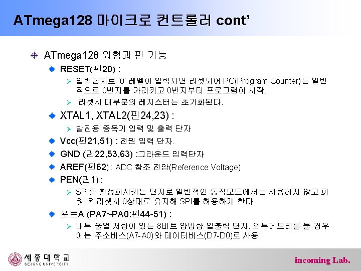
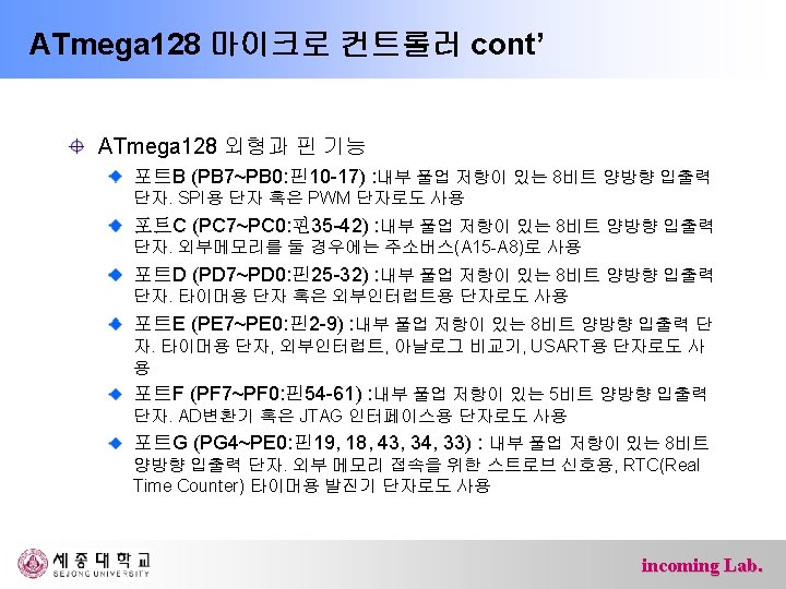
ATmega 128 마이크로 컨트롤러 cont’ ATmega 128 외형과 핀 기능 ATmega 128은 64핀을 갖는 TQFP(Thin Quad Flat Pack)형 또는 MLF(Micro Lead Frame)형이 있다. incoming Lab.
 incoming")
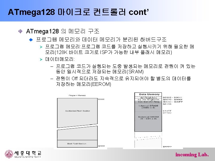
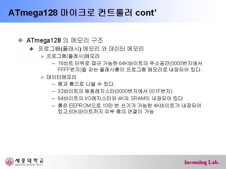
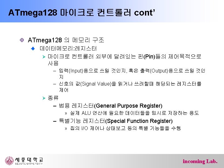
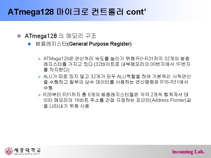
ATmega 128 마이크로 컨트롤러 cont’ ATmega 128 의 메모리 구조 범용레지스터(General Purpose Register) incoming Lab.
 – 내부")
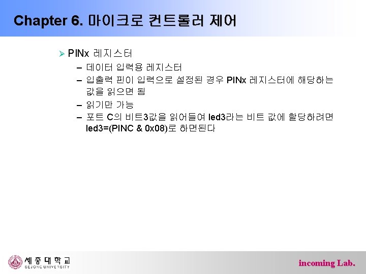
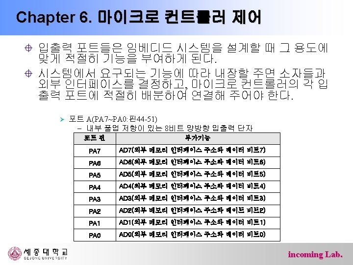
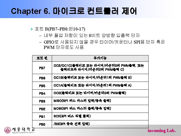
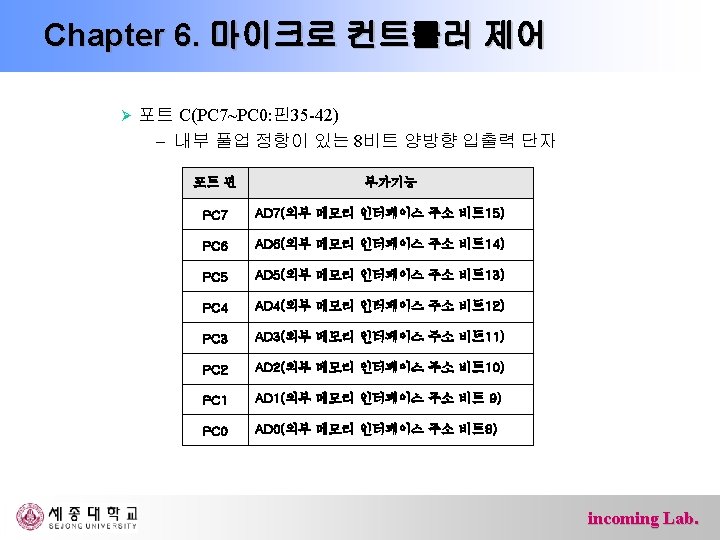
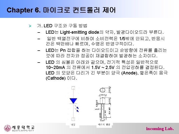
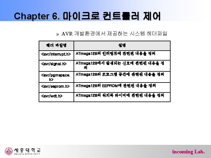
Chapter 6. 마이크로 컨트롤러 제어 Ø 포트 F(PF 7~PF 0: 핀54 -61) – 내부 풀업 저항이 있는 5피트 양방향 입출력 단자 – AD변환기 혹은 JTAG인터페이스용 단자 포트 핀 부가기능 PF 7 ADC 7/TDI(ADC 입력 채널 7 또는 JTAG Test Data Input) PF 6 ADC 6/TDO(ADC 입력 채널 6 또는 JTAG Test Data Output) PF 5 ADC 5/TMS(ADC 입력 채널 5 또는 JTAG Test Mode Select) PF 4 ADC 4/TCK(ADC 입력 채널 4 또는 JTAG Test Clock) PF 3 ADC 3 (ADC 입력 채널 3) PF 2 ADC 2 (ADC 입력 채널 2) PF 1 ADC 1 (ADC 입력 채널 1) PF 0 ADC 0 (ADC 입력 채널 0) incoming Lab.

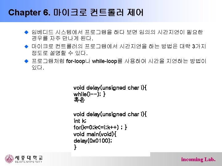
{ char i;")
Chapter 6. 마이크로 컨트롤러 제어 #include<avr/io. h> #include <util/delay. h> int main(){ char i; DDRB = 0 x 60; PORTB = 0; while(1){ PORTB = 0 x 40; for(i=0; i<10; i++) _delay_ms(100); PORTB = 0 x 20; for(i=0; i<100; i++) _delay_ms(10); } return 0; } incoming Lab.
{ DDRB = 0 x. FF;")
Chapter 6. 마이크로 컨트롤러 제어 #include<avr/io. h> int main(){ DDRB = 0 x. FF; DDRD = 0 x 00; while(1){ if(PIND & 0 x 40) PORTB |= 0 x 20; else PORTB &= ~0 x 20; if(PIND & 0 x 80) PORTB |= 0 x 40; else PORTB &= ~0 x 40; } return 0; } incoming Lab.
 전역(global) 변수 선언 int main(void) {")
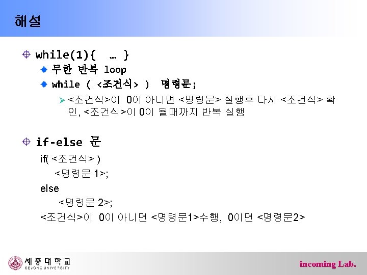
해설 C 프로그램 구조 전처리기 (#include, #define …) 전역(global) 변수 선언 int main(void) { /* local 변수 선언 */ /* 실행 code */ return 0; } incoming Lab.

해설 /* … */ : 주석, 프로그램 수행과 상관 없음 #include <avr/io. h> : AVR 프로세서 관련 header DDRB, DDRD 등의 정의가 포함 DDRB = 0 x. FF; 모든 bit를 output DDRB |= 0 x 60; /* 5, 6 bit 만 output */ DDRB = DDRB | 0 x 60; | : bit-wise OR DDRD = 0 x 00; 모든 bit를 input DDRD &= ~0 x. C 0; /* 7, 8 bit 만 output */ DDRD = DDRD & 0 x 3 F; & : bit-wise OR ~ : bit-wise NOT incoming Lab.

bitwise OR, AND, NOT 0 x 26, 0 x. C 7 0 x 26 = 0010 0110 0 x. C 7 = 1100 0111 0 x 26 | 0 x. C 7 0 x 26 & 0 x. C 7 ~0 x 26 ~0 x. C 7 incoming Lab.
 PORTB |= 0 x 20; else PORTB &=")
해설 if(PIND & 0 x 40) PORTB |= 0 x 20; else PORTB &= ~0 x 20; PIND & 0 x 40 : 6 번째 bit 확인 PORTB |= 0 x 20; /* 2번째 bit를 high */ PORTB &= ~0 x 20; /* 2번째 bit를 low */ incoming Lab.
 PORTB |= 0 x 40; else PORTB &=")
해설 if(PIND & 0 x 80) PORTB |= 0 x 40; else PORTB &= ~0 x 40; PIND & 0 x 80 : 7 번째 bit 확인 PORTB |= 0 x 40; /* 3번째 bit를 high */ PORTB &= ~0 x 40; /* 3번째 bit를 low */ incoming Lab.

Register 정의 <avr/io. h> iom 128. h <avr/iom 128. h> #define DDRB _SFR_IO 8(0 x 17) <avr/sfr_defs. h> #define _SFR_IO 8(io_addr) _MMIO_BYTE((io_addr) + __SFR_OFFSET) #define _MMIO_BYTE(mem_addr) (*(volatile uint 8_t *)(mem_addr)) # define __SFR_OFFSET 0 x 20 #define DDRB _SFR_IO 8(0 x 17) #define DDRB (*(volatile char *)0 x 37) incoming Lab.
0 x 37) (volatile char *)0 x 37 char 형")
#define DDRB (*(volatile char *)0 x 37) (volatile char *)0 x 37 char 형 data의 address char : 8 bit volatile : 하드웨어에 의해 변경될 수 있음을 의미 (volatile char *) 0 x 37: 0 x 37이 address임을 나타냄 (*(volatile char *)0 x 37) address가 0 x 37인 실제 위치 DDRB register 0 x 37 DDRB incoming Lab.

DDRB의 변형 # 1 #define my. DDRB … my. DDRB |= 0 x 60; … (*(volatile char *)0 x 37) #2 int main() { char *my. DDRB; my. DDRB = (char *)0 x 37; *my. DDRB |= 0 x 60; incoming Lab.
{ char")
Reference code #include <avr/io. h> // 최종에서는 제거 #include <util/delay. h> int main(){ char count = 0, status = 0, led; DDRB = // DDRB 셋팅 DDRD = // DDRD 셋팅 while(1) { … // 뒷 페이지 참조 _delay_ms(1); // debounce } return 0; } incoming Lab.
 { //sw 0 : 아래쪽 PORTB = // LED 끔")
Reference code if( ) { //sw 0 : 아래쪽 PORTB = // LED 끔 count = status = 0; // count/status reset } else { if (PIND & 0 x 40) // sw 1 아래쪽 status = 1; else { // sw 1 윗쪽 if( status == 1 ) { status = 0; count++; count %= 4; } } // LED 켜기 } incoming Lab.

Switch bounce incoming Lab.
 is software, consisting of programs and data, that")
Operating System An operating system (OS) is software, consisting of programs and data, that runs on computers and manages the computer hardware and provides common services for efficient execution of various application software. incoming Lab.

Embedded System An embedded system is a computer system designed to perform one or a few dedicated functions often with real-time computing constraints. No O/S or Real-time O/S device control : direct address access Ex) feature phone A general-purpose computer, such as a personal computer (PC), is designed to be flexible and to meet a wide range of end-user needs. O/S : windows, Mac OS X, UNIX, linux, … device control : through OS kernel and device driver Ex) smart phone (i. OS 4, Froyo (Android v 2. 2), WM, … ) incoming Lab.
- Slides: 66