Types of Soil Tracer Dye Tracers To study


.")


 Flow – Doesn’t disturb the flow field and")


- Slides: 51
Types of Soil Tracer
Dye Tracers To study the structure & preference flow phenomena (Flury and Wai, 2003). Most common – Food color Brilliant Blue FCF
Figure 1: Example of Staining Pattern within the Vertical Section of 2 Different Types of Soil.
Fluorescent Dye Tinopal CBS-X q Fluorescence - physical property of certain compounds - including some dyes. q In fluorescence, light photons of particular energy wavelengths are absorbed by the compound, then emitted at a lower energy level (longer wavelength). q Cases Study of using fluorescence as tracer: -Quantifying pesticide soil residues in the field through the development of sorption isotherms and the subsequent creation of a sorption coefficient(Kd) for the chemical and a specific soil type.
q Fluorescent dyes make excellent tracers for a variety of reasons, including: They are water soluble. They are highly detectable (some below 10 parts per trillion). They have extremely low toxicity ratings. They are inexpensive. They are fairly stable in a normal water environment. They have been used successfully for tracing for over one hundred years
RADIOACTIVE TRACERS v substances that contain a radioactive atom to allow easier detection and measurement v Radioactivity is the property possessed by some elements of spontaneously emitting energy in the form of particles or waves by disintegration of their atomic nuclei vit is possible to make a molecule of water in which one of the two hydrogen atoms is a radioactive tritium (hydrogen 3) atom v. This molecule behaves in almost the same way as a normal molecule of water.
• The main difference between the tracer molecule containing tritium and the normal molecule is that the tracer molecule continually gives off radiation that can be detected with a Geiger counter or some other type of radiation detection instrument.
Application v One application for the tracer molecule described above would be to monitor plant growth by watering plants with it. v The plants would take up the water and use it in leaves, roots, stems, flowers, and other parts in the same way it does with normal water. v In this case, however, it would be possible to find out how fast the water moves into any one part of the plant. v One would simply pass a Geiger counter over the plant at regular intervals and see where the water has gone.
TRACER TECHNIQUES AND SOIL GAS SURVEYS FOR THE DETECTION OF CONTAMINANT TRANSPORT USING CO 2 & O 2 TRACER ütracer sampling was carried out in the unsaturated zone and saturated zone. üareas of active microbial waste water degradation with elevated C 02 and depressed 02 in the soil gas relative
Radon Ø Radon is the only noble gas that is radioactive Ø Of all radon isotopes, 222 Rn is the most common and is a product of the uranium decay chain
Application of Rn: For remediation activities: Ø 222 Rn can be used as a Nonaqueous phase liquids (NAPL) tracer in the vadose zone as a partitioning tracer for locating and quantifying NAPL contamination in the subsurface and for monitoring changes in its quantities. Ø examples of NAPL mixtures : gasoline, diesel fuel and paraffin Ø method: (i) laboratory experiment –performed to determine the radon-partitioning coefficient for the NAPL mixtures (ii) field experiment – each site was covered with a suitable grid of soil gas sampling points. Finally, the lateral radon distribution pattern achieved on each of the sites was compared to the respective findings of the earlier research performed by conventional means.
Other application: Ø can be used to determine the residence time of recently infiltrated surface water in groundwater aquifers Ø to quantify groundwater inflow into lakes or artificial ponds, into wetlands, streams, and the ocean Ø a good tracer to observe transport of air masses and aerosols Ø used to study the origin of monsoon air and to monitor vertical atmospheric stability Ø useful for predicting earthquakes Ø to detect surface uranium ore deposits
Advantages of using tracer: 222 Rn as a Ø Diffusion lengths, particularly the relaxation depths of radon in unsaturated soils are large, thus it will not significantly disturbing the soil concentration profile Ø Radon detection is extremely accurate. Radioactive decay is measured as decays per second (dps), denoted as the SI unit Becquerel (Bq), with Bq = [s-1]. Ø Radon is an inert gas and does neither react with other chemicals in soil or air, nor it is biologically degraded.
TRACING TECHNIQUES/ METHODS Borehole methods
Magnetic & Gravity Logs Uses at contaminated site: Magnetic – Detecting buried metals in advance of drilling. Gravity – Possible use for performing structural interpretation in association with surface gravity measurement. Commonly used when presence of buried metals is suspected in the area of drilling.
Method description Magnetometer measure either intensity of the Earth’s total magnetic field at a point or gradients in the magnetic field. Fluxgate gradiometers allow continuous measurement of the gradient in the magnetic field along a transect. Magnetic: Borehole magnetometers operate on the same principle as surface fluxgate expect that they are attached to a cable that testing of boreholes to a depth of 25 feet
Gravity: Borehole gravimetry is a fairly recent extension of surface gravimetry. Microgravity instrumentation, specially designed for use in boreholes, measures vertical change in gravity.
Use of borehole magnetometer to detect buried ferrous containers.
Magnetic Advantage: Provide the most sensitive reading variations in the magnetic field. Magnetic Disadv. : 1) Require station measurement and 2) more susceptible to noise than fluxgate gradiometers
CALIPER LOG Its made by probes that used to measure the borehole diameter size. It also used to detect the porosity, permeability of soil and the rock condition Type of caliper; Ø Mechanical Ø Electrical Ø Acoustic
METHOD DESCRIPTION OF CALIPER LOG
Lowering the to the holes bottom with the arm resting against the body of the probe Arm opened with the electrical motor, and probe with arms touching the sides of boreholes is rised. Deflection of arm transmitted to the precision potentiometer and signal passed to the surface over the cable.
ADVANTANGES &DISADVANTAGES Advantages Disadvantages Equipment readily available Failure to centre properly in hole that are as a little a few degree off from vertical can give the erroneous reading Result can be read directly from log Special type required for inclined or horizontal boreholes Variety in types
PLATE FOR MECHANICAL CALIPER
Well test method Direct method Injection of tracer into a flow field at one point and observing its arrival at other points. Disadvantages: Slow groundwater velocities under natural conditions may result in long periods of time for tracers to migrate significant distances Heterogeneity of the aquifer materials need to use several observation points Due to slow tracer travel time in subsurface, observation wells are frequently placed close to the injection well but only small portion of the flow field is sampled The flow field maybe distorted by the use of numerous sampling devices.
Methods Single well tests Borehole dilution Single well pulse technique Multiple well tests Unstressed well field tests pumping and injection well test Discharged-recharged well test
Single well test Relate concentration decrease of a tracer introduced into a borehole with the interstitial velocity of the undisturbed groundwater flow in the aquifer. Change of tracer concentration is caused by any flow, both into and out of the borehole Which will cause dilution. A tracer is uniformly mixed in the wellbore and the rate of concentration changes caused by natural influx of groundwater into the borehole is used to calculate Darcy velocity through aquifer
Advantages: Measurements can be made over a short time period in a single borehole or piezometer. Darcy velocity can be calculated without having know velocity. If the gradient is known, the permeability can be calculated. Measurement of dilution at different depths in a well gives data for any stratum in the vertical profile of the aquifer. Determination of groundwater yield can be made.
Disadvantages: The measurement of Darcy velocity can be only applied to represent the velocity of the groundwater in the vicinity of the borehole Methods is not applicable when there are vertical movements or disturbance in the vicinity of the borehole.
Schematic of Borehole dilution with position of tracer front at T = 1, T =2 and T = 3
Dilution of tracer in borehole with time
Tracer concentration in the borehole is happen by the surrounding groundwater moving in the formation. Tracer dilution increase with time, thus the concentration of the tracer in the borehole decrease with time. The resulting velocity should be taken to represent the velocity of the groundwater in the vicinity of the borehole only. The results have local significance only.
SINGLE-WELL TECHNIQUE Advantage: Less tracer is required than in two well. The assumption of radial flow is generally valid, so natural aquifer velocity can be ignored, making solutions easier. Knowledge of the exact direction of flow is not necessary.
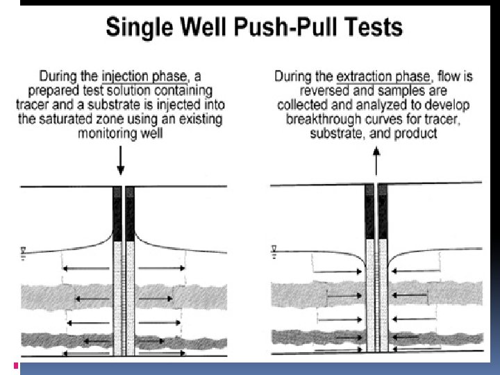
Two methods under single-well technique; Injection/withdrawal & borehole dilution. For injection/withdrawal, Results in a pore velocity value and a longitudinal dispersion coefficient Steps – given quantity of tracer is instantaneously added to the borehole, traces is mixed, two or three borehole volumes of fresh water is pumped in to force the tracer to penetrate the soil. After certain time, the borehole is pumped out a constant rate large enough to overcome the natural ground water flow. Tracer concentration is measured with time or pumped volume. The relative permeability of the layer is determined by measuring the concentration at various depths.
For borehole dilution, Used to measure magnitude and direction of horizontal tracer velocity and vertical flow. Steps – known quantity of tracer is instantaneously introduced into the borehole, the tracer is mixed well and the concentration decrease is measured with time. Tracer is generally introduced into an isolated volume of the borehole using packers. Most commonly used tracers are the radioactive tracers.
TWO WELL TECHNIQUES • Uniform (Natural) Flow – Doesn’t disturb the flow field and observation done in (OW) – Applicable at local for 2 -5 m and in-between 5 -100 m ( consume more time then radial test) – OW needed more if direction and magnitude of velocity unknown. • Radial (Induced) Flow – It work by altering the flow field of an aquifer by pumping solution are generally easier if the radical flow velocity greatly exceeds natural flow. The parameters (dispersion coefficient and porosity) same for both types.
PULSE WELL TEST • • wells should be opened and shut-in alternately for several times. single pulse-testing lies in that only one cycle of opening and shut-in of a well is required the time required for a well testing operation is about 1/3 of that for a multiple pulse-testing loss of oil production and trouble caused by alternately openning and shut-in the well can be reduced greatly
Borehole dilution
Multiple well test
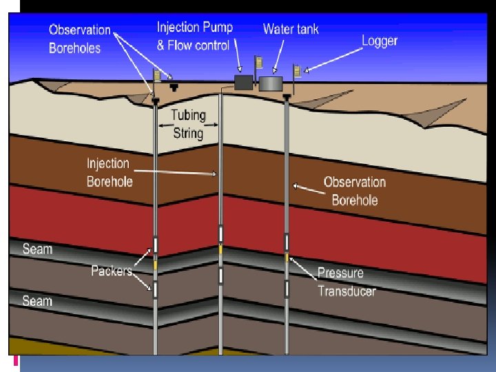
Pumping and injection well test Injection well system is the testing of the ability of the well to accept fluids. Perfomed by injecting fluids into the well or by pumping fluids out of the well. Conducted as an injection test. During the injection testing, careful observation of the monitor wells is perfomed to ensure that there is no hydraulic connection between the injection horizon and the monitoring zones, thereby verifying the intergrity of the injectin horizon.
Discharge – recharge well test using cross-correlation between flows and continuous head measurements in associated wells Suitable wells must lie within the recharge catchment of the spring display negligible phase lag between well and spring response to recharge method may depend on specific characteristics of aquifers to which it is applied, such as size of spring catchments, aquifer conductance, aquifer heterogeneity, and spatial distribution of recharge.