
Types of Semiconductor Detectors S W Mc Knight
- Slides: 30
Types of Semiconductor Detectors S W Mc. Knight and C A Di. Marzio
Outline • Bolometers • Photoconductive detectors • Photovoltaic detectors
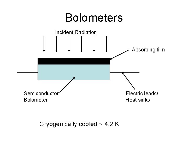
Bolometers Incident Radiation Absorbing film Semiconductor Bolometer Cryogenically cooled ~ 4. 2 K Electric leads/ Heat sinks
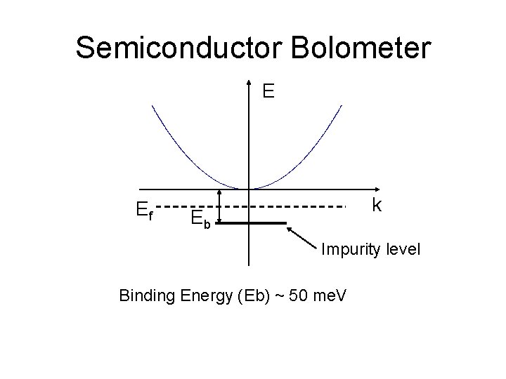
Semiconductor Bolometer E Ef k Eb Impurity level Binding Energy (Eb) ~ 50 me. V
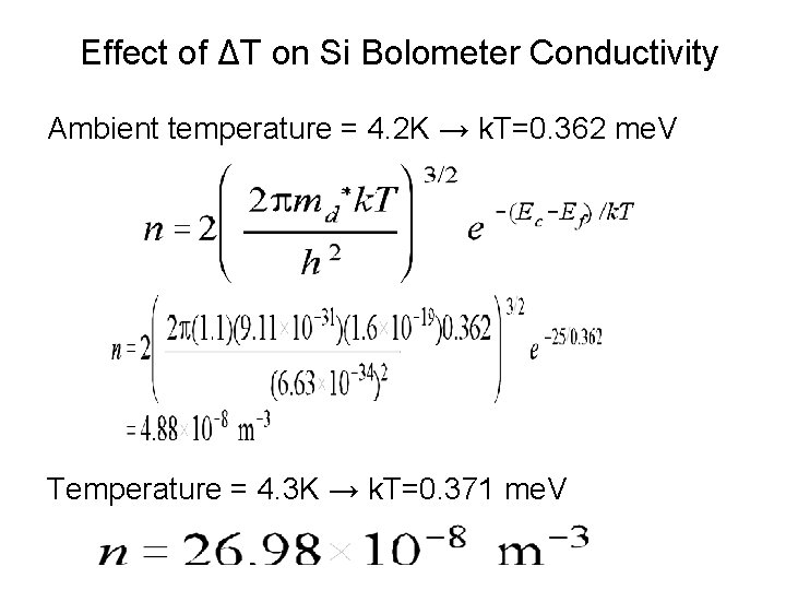
Effect of ΔT on Si Bolometer Conductivity Ambient temperature = 4. 2 K → k. T=0. 362 me. V Temperature = 4. 3 K → k. T=0. 371 me. V
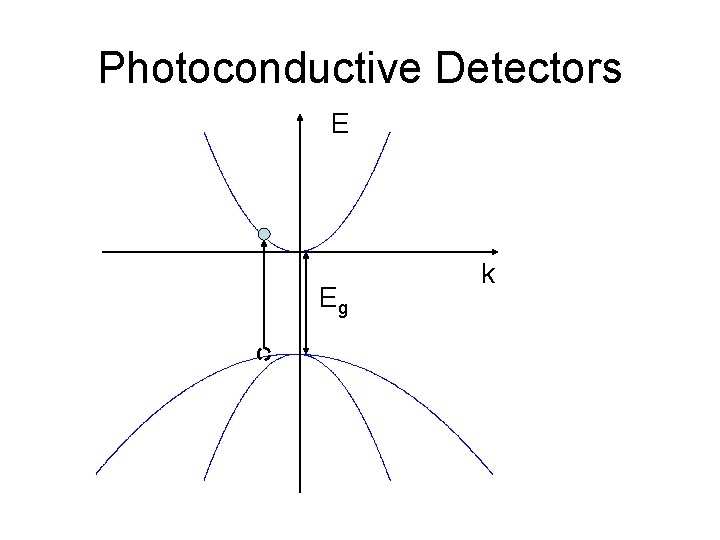
Photoconductive Detectors E Eg k
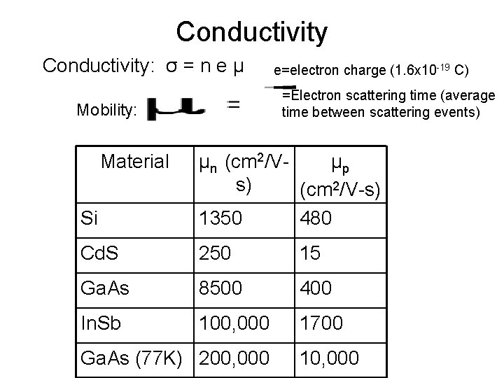
Conductivity: σ = n e μ =Electron scattering time (average time between scattering events) Mobility: Material e=electron charge (1. 6 x 10 -19 C) Si μn (cm 2/Vμp s) (cm 2/V-s) 1350 480 Cd. S 250 15 Ga. As 8500 400 In. Sb 100, 000 1700 Ga. As (77 K) 200, 000 10, 000
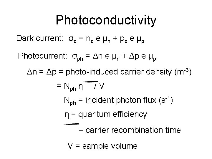
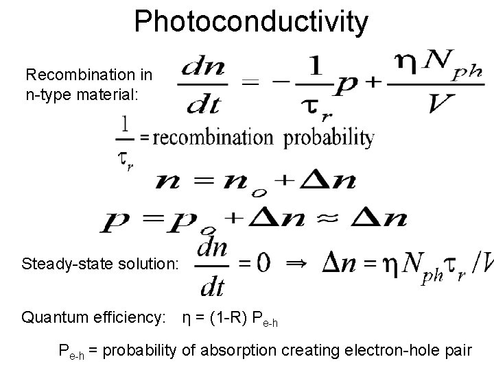
Photoconductivity Dark current: σd = no e μn + po e μp Photocurrent: σph = Δn e μn + Δp e μp Δn = Δp = photo-induced carrier density (m-3) = Nph η /V Nph = incident photon flux (s-1) η = quantum efficiency = carrier recombination time V = sample volume
Photoconductivity Recombination in n-type material: Steady-state solution: Quantum efficiency: η = (1 -R) Pe-h = probability of absorption creating electron-hole pair
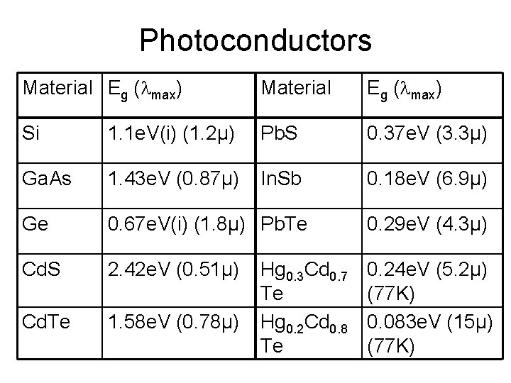
Photoconductors Material Eg ( max) Si 1. 1 e. V(i) (1. 2μ) Pb. S 0. 37 e. V (3. 3μ) Ga. As 1. 43 e. V (0. 87μ) In. Sb 0. 18 e. V (6. 9μ) Ge 0. 67 e. V(i) (1. 8μ) Pb. Te 0. 29 e. V (4. 3μ) Cd. S 2. 42 e. V (0. 51μ) Cd. Te 1. 58 e. V (0. 78μ) 0. 24 e. V (5. 2μ) (77 K) 0. 083 e. V (15μ) (77 K) Hg 0. 3 Cd 0. 7 Te Hg 0. 2 Cd 0. 8 Te
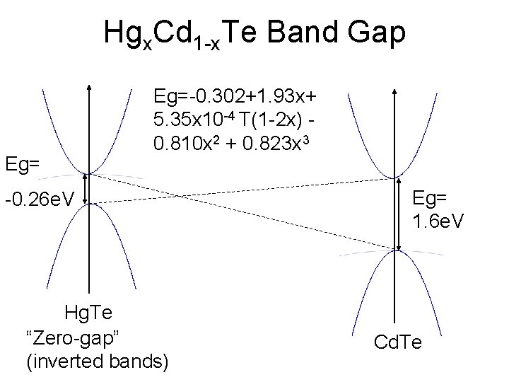
Hgx. Cd 1 -x. Te Band Gap Eg=-0. 302+1. 93 x+ 5. 35 x 10 -4 T(1 -2 x) 0. 810 x 2 + 0. 823 x 3 -0. 26 e. V Hg. Te “Zero-gap” (inverted bands) Eg= 1. 6 e. V Cd. Te
Photovoltaic Detectors • P-N junction detector • Incident light creates voltage • Same mechanism as solar cell
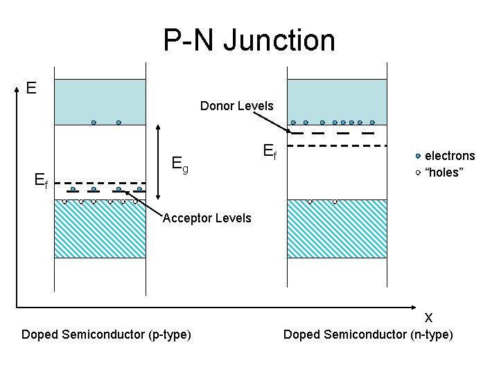
P-N Junction E Donor Levels Ef Eg Ef electrons “holes” Acceptor Levels x Doped Semiconductor (p-type) Doped Semiconductor (n-type)
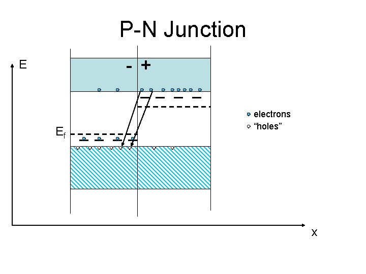
P-N Junction - + E Ef electrons “holes” x
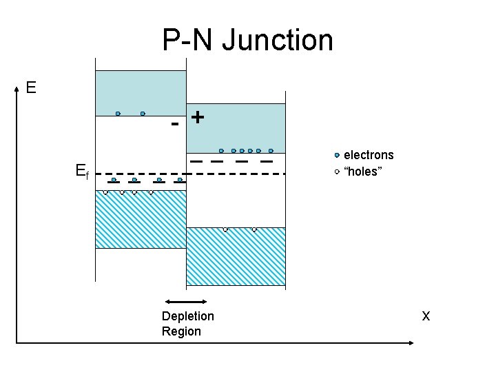
P-N Junction E - + electrons “holes” Ef Depletion Region x
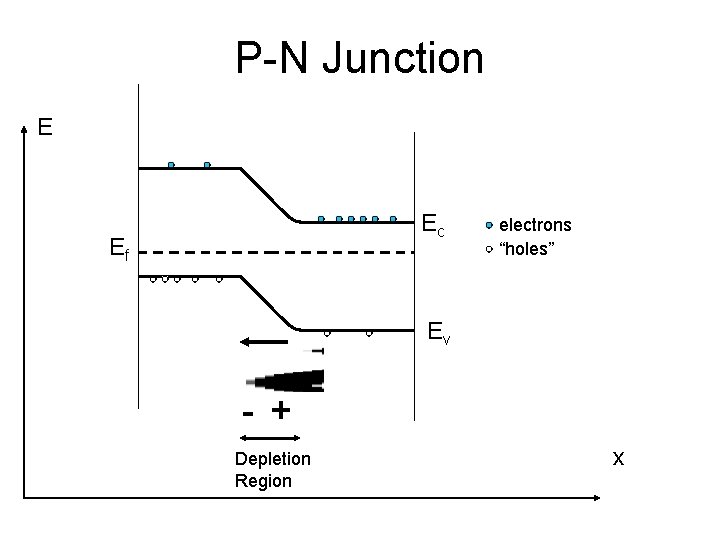
P-N Junction E Ec Ef electrons “holes” Ev - + Depletion Region x
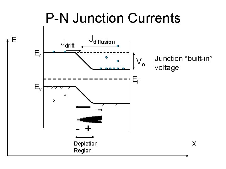
P-N Junction Currents E Ec Jdrift Jdiffusion Vo Junction “built-in” voltage Ef Ev - + Depletion Region x
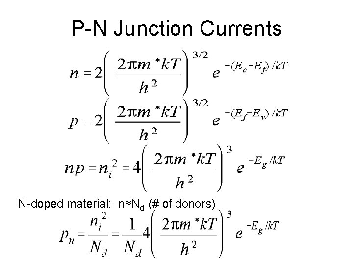
P-N Junction Currents N-doped material: n≈Nd (# of donors)
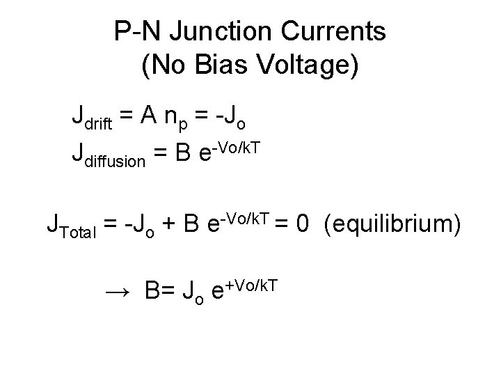
P-N Junction Currents (No Bias Voltage) Jdrift = A np = -Jo Jdiffusion = B e-Vo/k. T JTotal = -Jo + B e-Vo/k. T = 0 (equilibrium) → B= Jo e+Vo/k. T
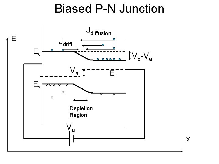
Biased P-N Junction E Ec Jdrift Jdiffusion Vo-Va Va Ef Ev Depletion Region Va x
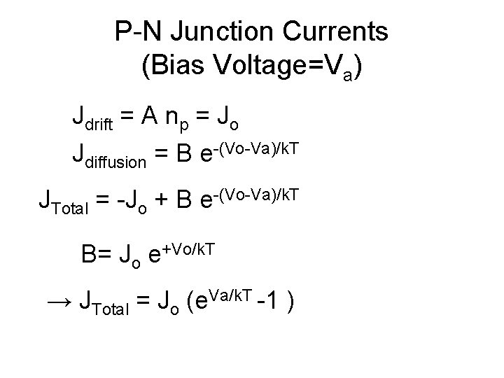
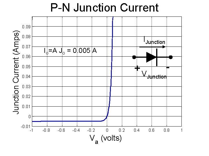
P-N Junction Currents (Bias Voltage=Va) Jdrift = A np = Jo Jdiffusion = B e-(Vo-Va)/k. T JTotal = -Jo + B e-(Vo-Va)/k. T B= Jo e+Vo/k. T → JTotal = Jo (e. Va/k. T -1 )
P-N Junction Current (Amps) 0. 09 0. 08 0. 07 0. 06 IJunction Io=A Jo = 0. 005 A +V 0. 05 0. 04 Junction 0. 03 0. 02 0. 01 0 -0. 01 -1 -0. 8 -0. 6 -0. 4 -0. 2 0 0. 2 Va (volts) 0. 4 0. 6 0. 8 1
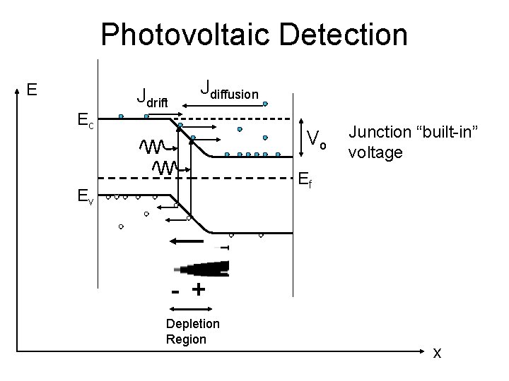
Photovoltaic Detection E Ec Jdrift Jdiffusion Vo Junction “built-in” voltage Ef Ev - + Depletion Region x
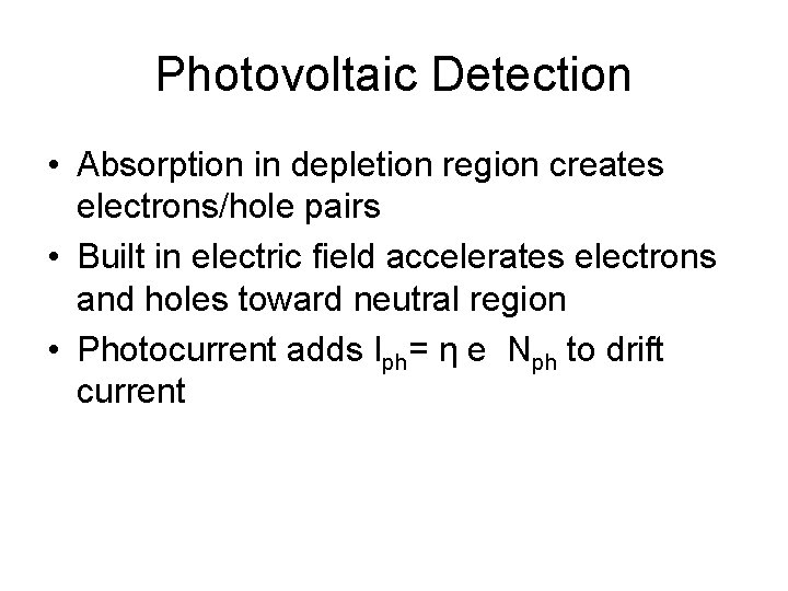
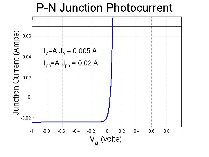
Photovoltaic Detection • Absorption in depletion region creates electrons/hole pairs • Built in electric field accelerates electrons and holes toward neutral region • Photocurrent adds Iph= η e Nph to drift current
Junction Current (Amps) P-N Junction Photocurrent 0. 06 0. 04 Io=A Jo = 0. 005 A Iph=A Jph = 0. 02 A 0. 02 0 -0. 02 -1 -0. 8 -0. 6 -0. 4 -0. 2 0 0. 2 Va (volts) 0. 4 0. 6 0. 8 1
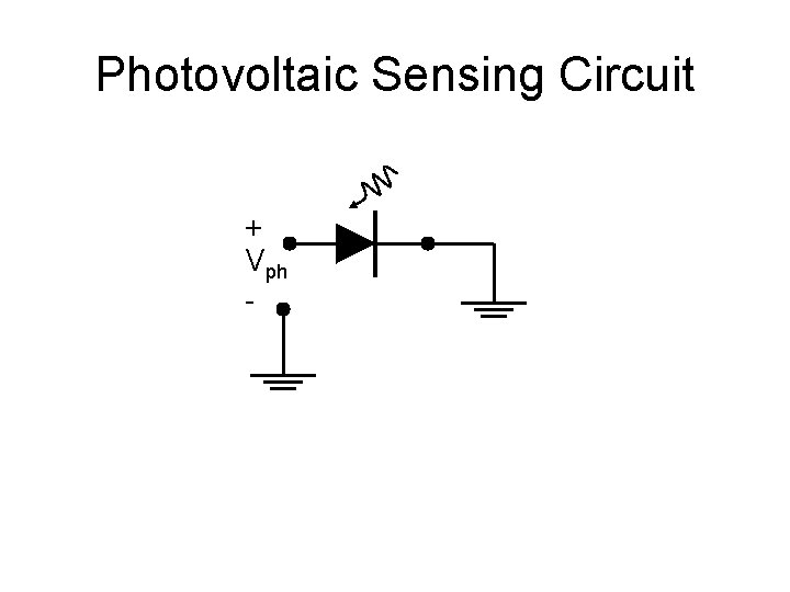
Photovoltaic Sensing Circuit + Vph -
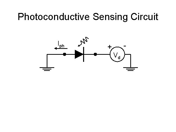
Photoconductive Sensing Circuit Iph - + Vd
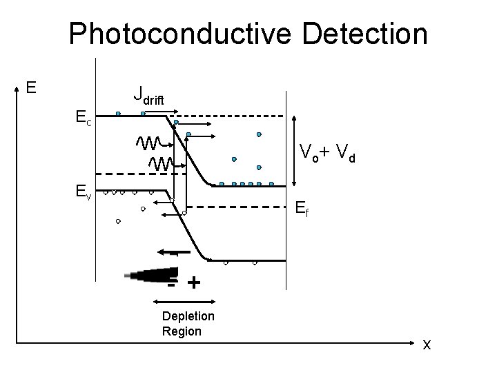
Photoconductive Detection E Ec Jdrift V o+ V d Ev Ef - + Depletion Region x
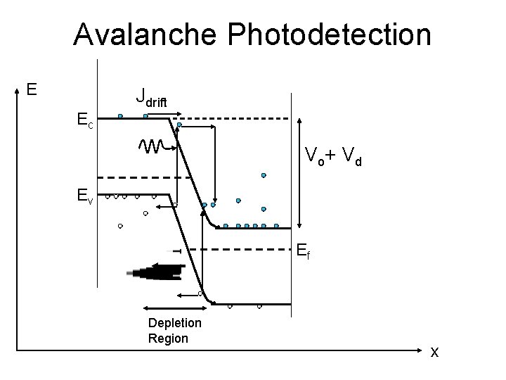
Avalanche Photodetection E Ec Jdrift V o+ V d Ev Ef Depletion Region x
Avalanche Photodiode • Large reverse bias on junction • Photoelectrons create electron/hole pairs in depletion region • Electron and holes can create more electron/hole pairs • Device has gain (like PMT)