Two Phase Flow in a Microgravity Environment Team


- Slides: 31
Two Phase Flow in a Microgravity Environment Team Members: Dustin Schlitt Shem Heiple Jason Mooney Brian Oneel Jim Cloer Academic Advisor Mark Weislogel
Mission While Two-Phase flow cycles are more efficient in the transfer of heat energy, they have been avoided in low gravity applications due to the lack of experimental data describing the behavior of the flow regimes. It was the goal of the Portland State Team to develop a reliable, inexpensive testing apparatus that would reproduce a steady slug flow regime that could be easily employed in ground based microgravity test facilities, such as NASA’s KC-135.
Two Phase Flow Over View
Micro-Gravity vs. Normal Gravity Fluid flows in which the effect of surface tension is significant are called capillary flows. Generally in normal gravity such flows are limited to small channels less than a few millimeters in diameter. The Bond number, Bo = ρgr 2/σ is the ratio of the gravitational force and the surface tension of the liquid, where ρ = density of fluid, g = the gravitational acceleration, r = the radius, σ = surface tension. When Bo >> 1, the gravitational force dominates fluid behavior. For Bo<< 1, surface tension plays a significant role in the behavior of the fluid. In the absence of gravity Bond numbers for large radius tubes can remain extremely small allowing flow patterns that are totally unique and unable to attain in normal gravity.
Bubbly Flow: Normal Gravity vs. Micro-Gravity
Slug Flow: Normal Gravity vs. Zero Gravity
Annular Flow: Normal Gravity vs. Zero Gravity
Design Requirements • Because the apparatus was to be used in NASA’s unique KC-135 test environment certain design criteria were imposed by NASA’s Reduced Gravity Flight Office. These deign criteria along with a weighing factor enabled the evaluation of various designs to a common metric. • The design criteria provided by NASA were broken down into the following categories: Performance, Ergonomics, Installation, and Safety. The following table highlights the design specifications.
Performance Customer Requirement 1 NASA The device is required Forward 9*9. 8 m/s 2 to withstand hard Aft 3*9. 8 m/s 2 landing loads. Down 6*9. 8 m/s 2 Lateral 2*9. 8 m/s 2 Up 2*9. 8 m/s 2 10 2 NASA The device is to 81. 64 kg impacting the structure withstand inadvertent at a velocity of. 6096 m/s. contact loads that 556 N over a 5. 08 cm radius could exceed “hard landing loads” locally. 10 3 NASA The device must attain steady state operation within a 10 short period of time. Metric Because of the limited time available to take data the device must reach steady state within 25 seconds. Importance
Ergonomics 1 Customer Requirement Metric NASA The device must For manual transport no one be easily person shall carry more than transported on and 222. 4 N. off the air craft. Importance 10 Installation 1 Customer Requirement Metric Importance NASA The apparatus must be secured to the floor of the aircraft The apparatus must not exceed 10 the maximum floor loading of 9576 N/m 2. The straps that will be used to secure the device to the floor of the air craft yield when 22241 N is applied, the device should not exceed this limit for any gravitational loading with less than a safety factor of 2
Safety Customer Requirement 1 NASA The device should not contain any sharp edges or points 2 NASA The device must have a “kill switch” for emergency shut down procedures 3 NASA 4 NASA Metric Importance 10 The “kill switch” must de-energize all components in the system to a safe state. 10 All electronic wiring and cabling must be 10 installed to both the Johnson Space Center Safety and Health Handbook and the National Electronic Code Standards. Liquids approved for use in the air craft must be contained Non-hazardous liquids in volume greater 10 than 177 ml must be doubly contained, and the containment method should be structurally sound able to with stand the inadvertent contact loads described in the performance section of this document.
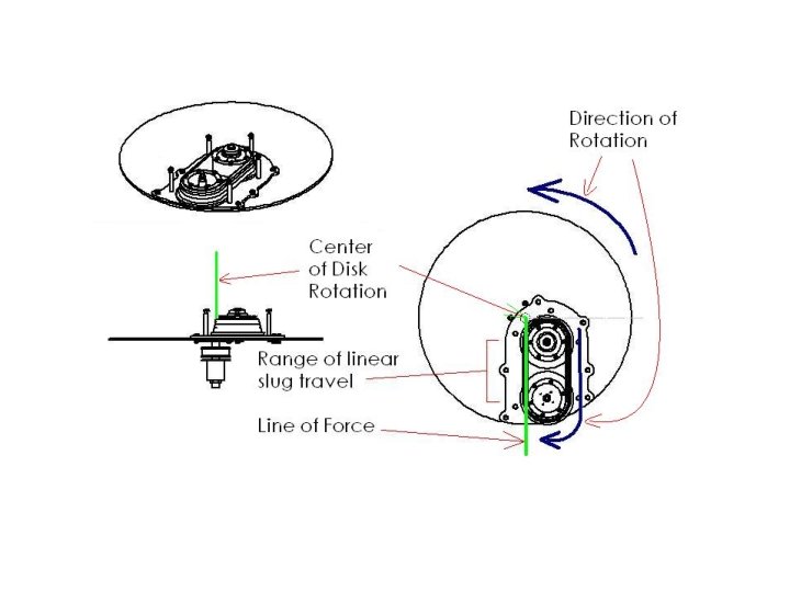
Theory The testing apparatus employs the use of four transparent flexible tubes partially filled with a fluid of known properties ( viscosity (μ), surface tension (σ), density (ρ) ). These tubes are made to rotate around two drums. The drums in turn are mounted on a large rotating disk. As the large disk rotates the liquid slugs in the tubes experience a centripetal acceleration. This centripetal acceleration is sufficient enough to drive the fluid motion while maintaining a capillary dominated flow. As the large disk is rotated the drums are made to rotate dragging the fluid from the outer edge of the drum to the linear portion of the tube path shown.
Theory A force balance in the linear path can be obtained between the acceleration force ( Fa ), the viscous dissipation force( Fμ ), and the surface tension force ( Fσ ). When these forces balance a steady slug velocity develops. V Rrec Radv
Balancing forces yields, From this force balance the governing differential equation describing this flow is, At steady state the governing differential equation reduces to,
Our Design 1. Aluminum Frame 2. Mounting Plate 3. Motor/Gear Box ( Large Disk ) 4. Motor/Gear Box ( Drums ) 5. Drum Pack Assembly 6. Counter Weight 7. Digital Video Camera 8. Large Disk Rotational Velocity Display 9. Back Light Switch 10. DV Monitor 11. Speed Controls ( Large Disk, Drum ) 12. Power Supply 13. Outreach Experiment Controls 14. Outreach Experiment Housing
Our Design
Our Design
The Zero G Experience
KC 135 Reduced Gravity Aircraft Number of Parabolas: 32 Free Fall Time : 21 seconds Top of Parabola : 32, 000 ft Bottom of Parabola : 24, 000 ft
Not Zero Gravity…but free fall
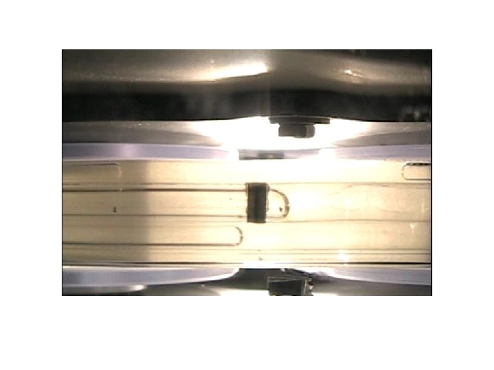
Fluids in Reduced Gravity
Reduced Gravity Fun
Data Analysis
Data Analysis • Steady state slug velocity. • Steady slug length. • At least one revolution of the tube loop during steady state.
Measuring Film Thickness
Average Velocity
Change In Slug Length
Comparison of Data Against Previous Correlations
Results • Steady state flow ± 1% • Prediction match • Errors – Aircraft – Apparatus – Film thickness sensitivity