
TriLevelCell Phase Change Memory PCM Toward an Efficient

- Slides: 36
Tri-Level-Cell Phase Change Memory (PCM): Toward an Efficient and Reliable Memory System Nak Hee Seong Lee Sungkap Yeo Hsien-Hsin S. School of Electrical and Computer Engineering Georgia Institute of Technology Atlanta, GA 30332 nakhee. seong@gmail. com {sungkap, leehs}@gatech. edu Presented By: Anand Dhole Shalini Satre
Contents �PCM �Background and Motivation �Tri-Level-Cell (3 LC) PCM � 3 LC PCM in Practice �Evaluation �Conclusion
�PCM �Background and Motivation �Tri-Level-Cell (3 LC) PCM � 3 LC PCM in Practice �Evaluation �Conclusion
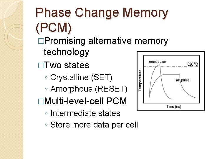
Phase Change Memory (PCM) �Promising alternative memory technology �Two states ◦ Crystalline (SET) ◦ Amorphous (RESET) �Multi-level-cell PCM ◦ Intermediate states ◦ Store more data per cell
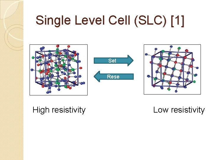
Single Level Cell (SLC) [1] Set Rese t High resistivity Low resistivity
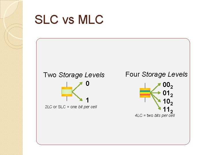
SLC vs MLC Two Storage Levels 0 1 2 LC or SLC = one bit per cell Four Storage Levels 002 012 102 112 4 LC = two bits per cell
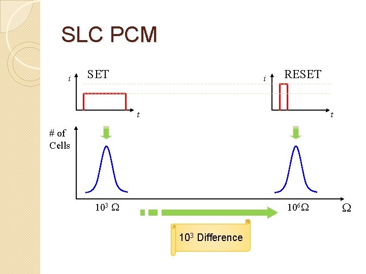
SLC PCM i SET i RESET t t # of Cells 103 106 103 Difference
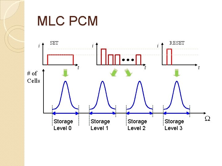
MLC PCM i SET i t # of Cells 1 k Storage Level 0 i RESET t Storage Level 1 Storage Level 2 t 1 M Storage Level 3
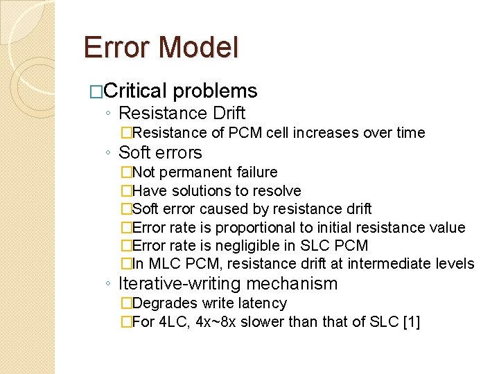
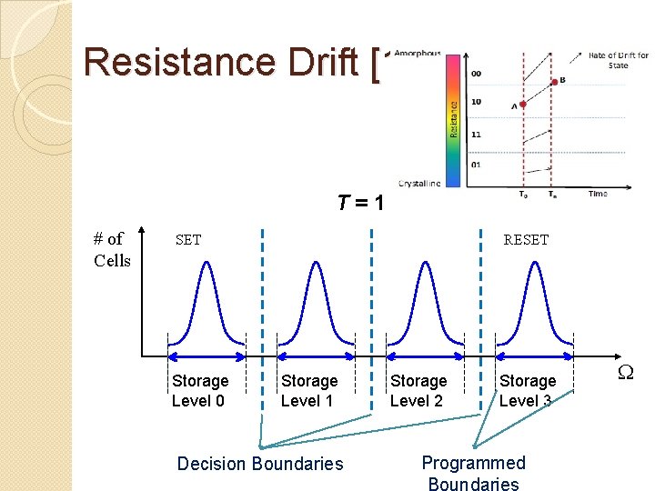
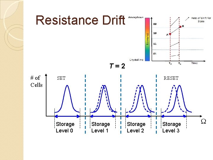
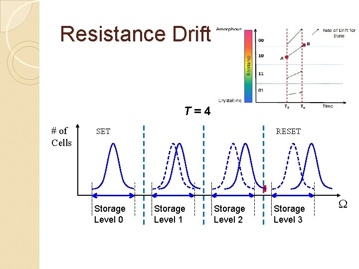
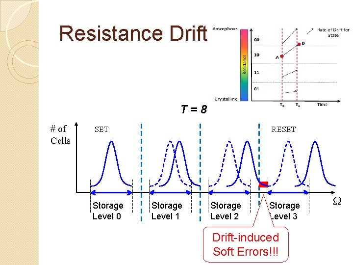
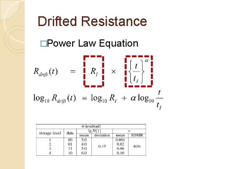
Error Model �Critical problems ◦ Resistance Drift �Resistance of PCM cell increases over time ◦ Soft errors �Not permanent failure �Have solutions to resolve �Soft error caused by resistance drift �Error rate is proportional to initial resistance value �Error rate is negligible in SLC PCM �In MLC PCM, resistance drift at intermediate levels ◦ Iterative-writing mechanism �Degrades write latency �For 4 LC, 4 x~8 x slower than that of SLC [1]
Resistance Drift [1] T=1 # of Cells SET Storage Level 0 RESET Storage Level 1 Decision Boundaries Storage Level 2 Storage Level 3 Programmed
Resistance Drift T=2 # of Cells SET Storage Level 0 RESET Storage Level 1 Storage Level 2 Storage Level 3
Resistance Drift T=4 # of Cells SET Storage Level 0 RESET Storage Level 1 Storage Level 2 Storage Level 3
Resistance Drift T=8 # of Cells SET Storage Level 0 RESET Storage Level 1 Storage Level 2 Storage Level 3 Drift-induced Soft Errors!!!
Drifted Resistance �Power Law Equation
Proposed Solution �Proposed tri-level-cell PCM ◦ Soft error rate matches that of DRAM ◦ Gain performance of SLC PCM
�PCM �Background and Motivation �Tri-Level-Cell (3 LC) PCM � 3 LC PCM in Practice �Evaluation �Conclusion
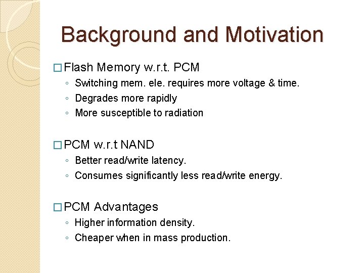
Background and Motivation � Flash Memory w. r. t. PCM ◦ Switching mem. ele. requires more voltage & time. ◦ Degrades more rapidly ◦ More susceptible to radiation � PCM w. r. t NAND ◦ Better read/write latency. ◦ Consumes significantly less read/write energy. � PCM Advantages ◦ Higher information density. ◦ Cheaper when in mass production.
Background and Motivation cont… �MLC PCM ◦ Many intermediate states between SET and RESET ◦ E. g. 8 LC PCM stores three bits per cell ◦ Soft error rate(SER) is higher than that of DRAM ◦ SER increases over time along with resistance ◦ Error correction Methods �Time-aware error correction scheme �Scrub mechanism
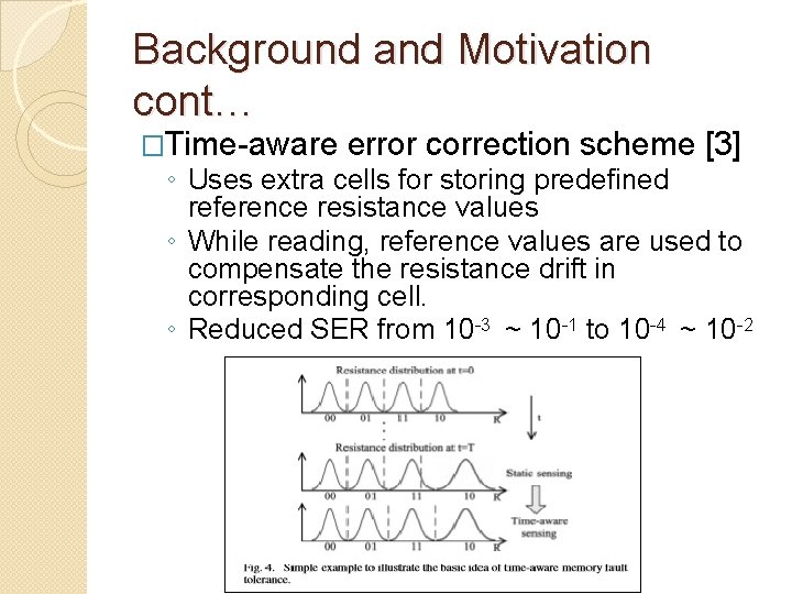
Background and Motivation cont… �Time-aware error correction scheme [3] ◦ Uses extra cells for storing predefined reference resistance values ◦ While reading, reference values are used to compensate the resistance drift in corresponding cell. ◦ Reduced SER from 10 -3 ~ 10 -1 to 10 -4 ~ 10 -2
Background and Motivation cont… �Scrub Mechanism [2] ◦ Reduced 99. 6% of uncorrectable errors ◦ Memory controller spend more time in scrubbing �DRAM-style self refresh [3] ◦ Cells with correct information also gets refreshed ◦ Higher chip-level power ◦ Frequent write decreases lifespan ◦ Slower responsiveness
�PCM �Background and Motivation �Tri-Level-Cell (3 LC) PCM � 3 LC PCM in Practice �Evaluation �Conclusion
3 LC PCM �Each cell has three storage levels �Removed most error-prone state from 4 LC PCM i. e. Third storage level �Drift is proportional to resistance �Removes errors generated by third as well as most of the errors generated by second storage level
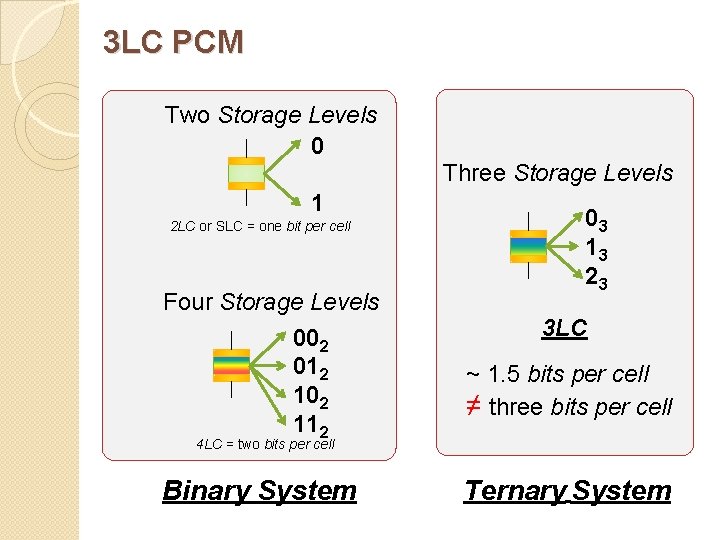
3 LC PCM Two Storage Levels 0 Three Storage Levels 1 2 LC or SLC = one bit per cell Four Storage Levels 002 012 102 112 03 13 23 3 LC ~ 1. 5 bits per cell ≠ three bits per cell 4 LC = two bits per cell Binary System Ternary System
�PCM �Background and Motivation �Tri-Level-Cell (3 LC) PCM � 3 LC PCM in Practice �Evaluation �Conclusion
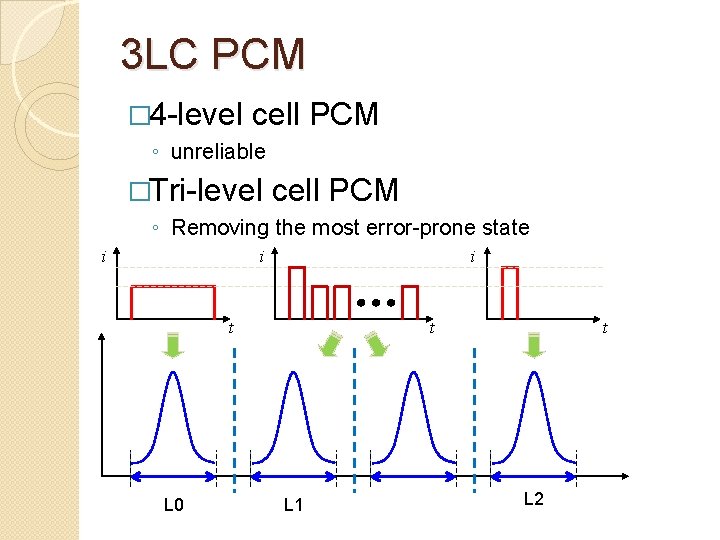
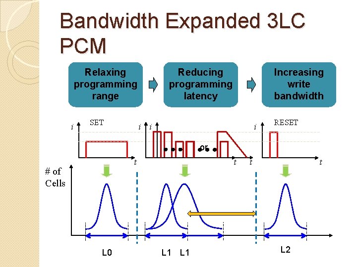
3 LC PCM � 4 -level cell PCM ◦ unreliable �Tri-level cell PCM ◦ Removing the most error-prone state i i i t L 0 t L 1 t L 2
Bandwidth Expanded 3 LC PCM Relaxing programming range i SET Reducing programming latency Increasing write bandwidth i i i RESET or t # of Cells L 0 t L 1 t t L 2
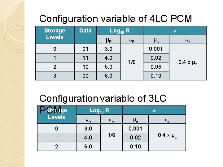
Configuration variable of 4 LC PCM Storage Levels Data Log 10 R 0 01 3. 0 1 11 4. 0 2 10 5. 0 3 00 6. 0 µR α ϭR µα ϭα 0. 001 1/6 0. 02 0. 4 x µα 0. 06 0. 10 Configuration variable of 3 LC α Storage Log R PCM 10 Levels µR 0 3. 0 1 4. 0 2 6. 0 ϭR µα ϭα 0. 001 1/6 0. 02 0. 10 0. 4 x µα
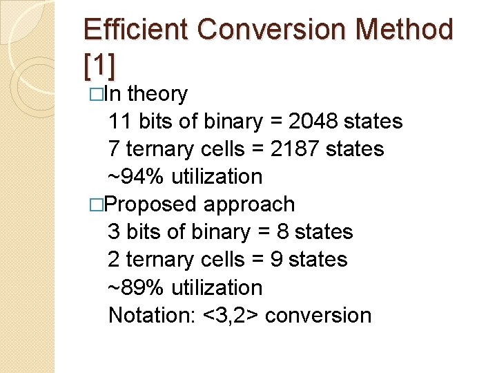
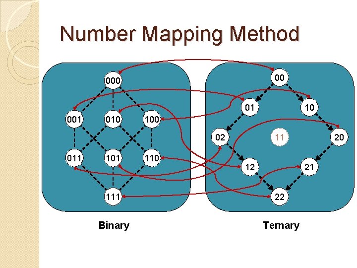
Efficient Conversion Method [1] �In theory 11 bits of binary = 2048 states 7 ternary cells = 2187 states ~94% utilization �Proposed approach 3 bits of binary = 8 states 2 ternary cells = 9 states ~89% utilization Notation: <3, 2> conversion
Number Mapping Method 00 01 001 010 100 02 011 10 110 11 12 20 21 111 22 Binary Ternary
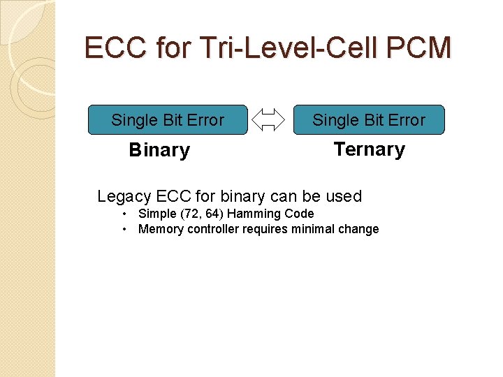
ECC for Tri-Level-Cell PCM Single Bit Error Binary Single Bit Error Ternary Legacy ECC for binary can be used • Simple (72, 64) Hamming Code • Memory controller requires minimal change
�PCM �Background and Motivation �Tri-Level-Cell (3 LC) PCM � 3 LC PCM in Practice �Evaluation �Conclusion
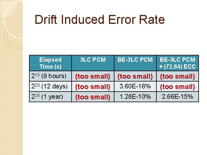
Drift Induced Error Rate Elapsed Time (s) 3 LC PCM BE-3 LC PCM + (72, 64) ECC 215 (9 hours) (too small) 3. 60 E-16% (too small) 1. 28 E-10% 2. 66 E-15% 220 (12 days) 225 (1 year)
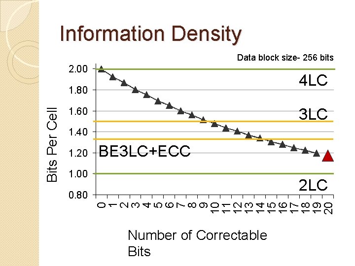
Information Density Data block size- 256 bits 2. 00 4 LC 3 LC 1. 60 1. 40 1. 20 BE 3 LC+ECC 1. 00 2 LC 0. 80 0 1 2 3 4 5 6 7 8 9 10 11 12 13 14 15 16 17 18 19 20 Bits Per Cell 1. 80 Number of Correctable Bits
�PCM �Background and Motivation �Tri-Level-Cell (3 LC) PCM � 3 LC PCM in Practice �Evaluation �Conclusion
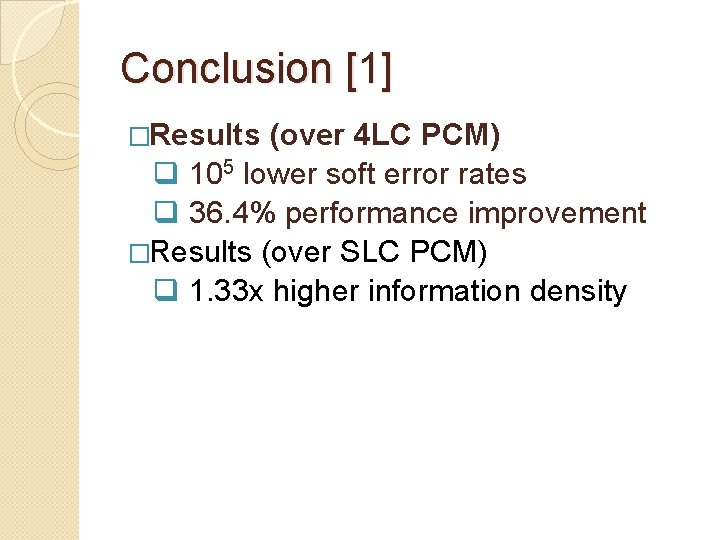
Conclusion [1] �Results (over 4 LC PCM) q 105 lower soft error rates q 36. 4% performance improvement �Results (over SLC PCM) q 1. 33 x higher information density
References 1) Nak Hee Seong, Sungkap Yeo, Hsien-Hsin S. Lee, "Tri-Level-Cell Phase Change Memory: Toward an Efficient and Reliable Memory System", ISCA'13 2) M. Awasthi, M. Shevgoor, K. Sudan, B. Rajendran, R. Balasubramonian, and V. Srinivasan, “Efficient Scrub Mechanisms for Error-Prone Emerging Memories, ” in Proceedings of the International Symposium on High Performance Computer Architecture, 2012. vol. 19, no. 8, pp. 1357– 1367, 2011 3) W. Xu and T. Zhang, “A time-aware fault tolerance scheme to improve reliability of multilevel phase-change memory in the presence of significant resistance drift, ” IEEE Transactions on Very Large Scale Integration (VLSI) Systems, vol. 19, no. 8, pp. 1357– 1367, 2011. 4) T. Nirschl, J. Phipp, T. Happ, G. Burr, B. Rajendran, M. Lee, A. Schrott, M. Yang, M. Breitwisch, C. Chen et al. , “Write strategies for 2 and 4 -bit multilevel phase-change memory, ” in IEEE International Electron Devices Meeting (IEDM), 2007, pp. 461– 464. 5) N. Papandreou, H. Pozidis, T. Mittelholzer, G. Close, M. Breitwisch, C. Lam, and E. Eleftheriou, “Drift-tolerant multilevel phase-change memory, ” in 2011 3 rd IEEE International Memory Workshop (IMW). IEEE, pp. 1– 4. 6) R. Hamming, “Error detecting and error correcting codes, ” Bell System Technical Journal, vol. 29, no. 2, pp. 147– 160, 1950.