Transportation Engineering Bridge Engineering Prof Rajesh Bhagat Asst
 Prof. Rajesh Bhagat Asst. Professor, CED, YCCE, Nagpur B. E.")
Transportation Engineering (Bridge Engineering) Prof. Rajesh Bhagat Asst. Professor, CED, YCCE, Nagpur B. E. (Civil Engg. ) GCOE, Amravati M. Tech. (Enviro. Engg. ) VNIT, Nagpur Experience & Achievement: v Selected Scientist, NEERI-CSIR, Govt. of India. v GATE Qualified Three Times. v UGC - NET Qualified in First Attempt. v Selected Junior Engineer, ZP Washim. v Three Times Selected as UGC Approved Assistant Professor. v Assistant Professor, PCE, Nagpur. v Assistant Professor, Cummins College of Engg. For Women, Nagpur v Topper of Pre-Ph. D Course Work at UGC-HRDC, RTMNU Nagpur Mobile No. : - 8483002277 / 8483003474 Email ID : - rajeysh 7 bhagat@gmail. com Website: - www. rajeysh 7 bhagat. wordpress. com
 Bridges: Introduction, Components, classification and identification. 2) Data Collection, site selection, Economic")
UNIT-V 1) Bridges: Introduction, Components, classification and identification. 2) Data Collection, site selection, Economic Span, Estimation of flood discharge, waterway, scours depth, depth of foundation, Afflux, clearance and free board. 3) Loads, Forces and Stresses for Bridges. 2
 Bridge Engineering by S. P. Bindra, Dhanpat Rai Publication. 2) Indian Road")
References: 1) Bridge Engineering by S. P. Bindra, Dhanpat Rai Publication. 2) Indian Road Congress, IRC handbooks , International Code Council. 3) Traffic and Highway Engineering by J. Garber and L. A. Hoel, Thomson Learning, Inc. 4) Highway engineering by Khanna & Justo, Nem Chand & Bros. Pub.

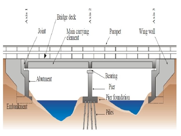
Bridge : The drainage structure which facilitates a communication route for carrying road or railway traffic across an obstruction or depression with or without water is called a bridge. Bridge Engineering: The branch of civil engineering which deals with the design, construction and maintenance of bridge is called Bridge Engineering. Major Bridge: Total length varying from 30 m to 120 m. Minor Bridge: Total length less than 30 m.

Culvert: The bridge having total length 6 m or less is called a culvert. Linear Water ways: The length available between extreme edges of water surface at the highest flood level, measured at right angles to the abutment faces of a bridge is called as linear waterways. Afflux: The heading up of the water above its normal level while passing under the bridge is called afflux. Abutments: The end support of a bridge superstructure are termed as abutment. Wing Wall: The wall constructed on both sides of abutment to retain the earth banks of the river or of the bridge approaches are called wing wall. Piers: The intermediate support of a bridge superstructure are known as piers.
")
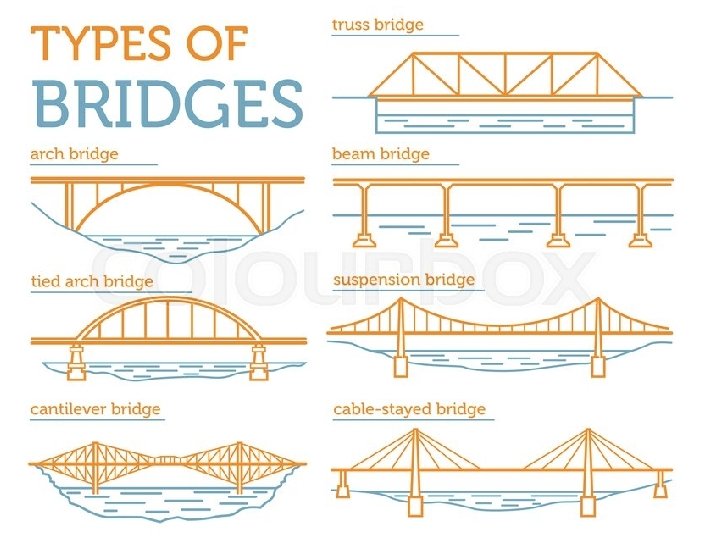
Bridge: Bridges can be classified into various types based on the following factors: 1) Materials : RCC Bridge, Masonry Bridge, Steel Bridge, Timber Bridge, Pre. Stressed Concrete Bridge. 2) Floor : Deck Type, Thorough Bridge. 3) Purpose : Highway Bridge, Railway Bridge, Aqueduct. 4) Superstructure : Portal Frame, Balanced Cantilever Bridge, Suspension Bridge. 5) Flood Level : Submersible Bridge 6) Span Length : Culvert, Minor, & Major bridges. 7) Fixed or Movable : Swinging Bridge, Bascule Bridge & Lift Bridge.
 Arch Culvert. 2) Slab Culvert. 3) Pipe Culvert. 4) Box Culvert.")
Culverts: 1) Arch Culvert. 2) Slab Culvert. 3) Pipe Culvert. 4) Box Culvert.

 The bridge having their superstructure consisting of pre-stressed concrete members")
Pre-stressed Concrete Bridge: 1) The bridge having their superstructure consisting of pre-stressed concrete members in any structural form, which support the bridge floor are known as prestressed concrete bridge. 2) The art of pre-stressing consists of inducing compressive stresses in the tensile zones of the members. The aim of pre-stressing the members is to avoid cracking of concrete due to principal tensile stresses under severe loads. 3) The technique of pre-stressing checks the tendency of cracking and increase the shearing capacity of the ordinary reinforced concrete. 4) This enables the use of thinner webs, thereby resulting saving in material, dead load and ultimately economy in the design of the bridge. 5) Thus the application of the concept of pre-stressing to structural concrete members has enlarged the span range of concrete bridges.
 Higher load carrying capacity 2) Reduced deflection")
Pre-stressed Concrete Bridge: Advantages & Disadvantages 1) Higher load carrying capacity 2) Reduced deflection of girders 3) Fewer expansion of joints 4) More aesthetic appearance 5) More effective use of precast members 6) Maintenance cost is less 7) More smooth deck and high speed driving 8) Careful supervision 9) Special equipment for construction 10) High tensile steel required which is more costly than ordinarily mild steel

Movable Bridge: Movable spans of bridge are sometimes used over the navigable channels where permanent and sufficient clear waterway can not be provided. They are needed in order to provide a passage for the masted vessels or steamers when the bridge is to be across a navigable river or dock. 1) Swing Bridge consists of balanced girders swinging round a quadrant of a circle over a pier or a pivot or on a turn table. 2) Bascule Bridge can be raised slightly to permit the passage of numerous small boats which fail to clear the closed span by a small origin. They revolve about a horizontal axis and in a vertical position and when lifted attain an upright position. 3) Traverser Bridge can be rolled backwards and forwards across the opening. They are provided with rollers on the shore which helps in rolling it off its position along the approach.

Movable Bridge: Movable spans of bridge are sometimes used over the navigable channels where permanent and sufficient clear waterway can not be provided. They are needed in order to provide a passage for the masted vessels or steamers when the bridge is to be across a navigable river or dock. 4) Transporter Bridge consists of a cradle which moves under an overhead bridge. The overhead bridge is spanned on high towers provided on each bank. 5) Lift Bridge : The vertical lift bridge have proved to be more economical both in construction and operation than swing and bascule bridge.
 Used in places where it is difficult to adopt other types")
Suspension Bridge: 1) Used in places where it is difficult to adopt other types of bridges. 2) They are economically used even for every large spans. 3) Generally they are single span bridge. 4) There are two main cables on each side of the roadways. 5) They are carried over solid piers and are securely anchored to the banks. 6) The roadways is suspended from two main cables by means of suspenders. 7) The cables are carried over the saddle provided on the pier top. The saddles are either bolted to piers or they rest on rollers to allow for longitudinal movement resulting from any alternation in cable length.
 The bridge having its floor supported or suspended at the bottom")
Through Bridge: 1) The bridge having its floor supported or suspended at the bottom of the superstructure is known as through bridge. 2) This bridge is constructed when the vertical distance between the HFL and the ground level of approaches is not sufficient to accommodate the superstructure with a suitable free board.
 The bridge having its floor supported at the top of superstructure")
Deck Bridge: 1) The bridge having its floor supported at the top of superstructure is called a deck bridge. 2) Constructed where the vertical distance between the HFL and ground level of the approaches is sufficient to accommodate the superstructre with a suitable free board.
 Normally an abutment has one front wall on")
Return Walls & Wing Walls: 1) Normally an abutment has one front wall on which the deck or girder of the bridge is supported and side walls perpendicular to front wall which are also known as return walls when they are parallel to the bridge and wing walls when they are curved in plan or at any other angle. 2) The design of wing walls is independent. For straight wing walls it may be assumed that the equilibrium of each of their cross sections is comparable with that of an imaginary horizontal wall of indefinite length of the same cross section holding up an embankment. 3) Generally the wing wall have steadily decreasing cross sections. 4) Their mean thickness at any given section is one third of their height. 5) The design of the wing walls mainly depends upon the nature of the soil in the embankment.
 The nature of the river")
Factors Governing Choice of Type of Bridge : 1) The nature of the river & its bed soil and Physical features of the site. 2) Availability of materials, workers & funds. 3) Volume and the nature of the traffic. 4) Time limit within which the bridge is required to be completed. 5) Whether navigation is done in the river or not. 6) Economic span length of the bridge. 7) Facilities available during construction. 8) Facilities available for maintenance. 9) Foundation Condition. 10) Climatic & Strategic Condition 11) Hydraulic Data and Live loads on the bridge. 12) Length & width of the bridge
 Suitable bearing strata")
Points to be Considered for Selection of a Bridge Site: 1) Suitable bearing strata in the stream at a short depth may be available and it should be geologically suitable. 2) The stream at bridge site should be narrow and straight reach. 3) The site should have firm, straight and high banks. 4) The flow of water at site should be steady and free from whirls and cross currents. 5) Easy availability of labor, materials and transport facility nearing site. 6) The bridge should not be on the curve and it should be suitable for navigation purpose.

Bridge Numbering : The numbers are given in the form of fraction, the numerator denoting the number of kilometers in which the structure is situated and the denominator the kilometer-wise serial number of the structure.
 Traffic Data 2)")
Data to be Collected for Selection of a Bridge Site: 1) Traffic Data 2) Hydraulic data based on stream characteristics 3) Geological Data 4) Climatic Data 5) Catchment Area & Runoff 6) Alignment Data 7) Superstructure Data 8) Foundation Data 9) Availability of Electric Power, Labor, Materials and Transport Facilities, etc.
 General Data: Road type, BM, Season & its")
Design Data for Major Bridges: 1) General Data: Road type, BM, Season & its duration, alternative arrangement 2) Catchment area & runoff: 3) Nature of stream: Types of stream, water level, 4) Alignment & Approaches: Right & left Approach, Bridge visibility. 5) Superstructure: Clear roadway over bridge, footpath 6) Foundation Data: Type of foundation and suitability. 7) Existing Structure: Details of existing bridge. 8) Other: Locality, Facility Nearby, etc.

Wind Load: Wind load forces should be considered to act horizontally and in such a direction that the resultant stresses in the member under consideration are the maximum. It may be assumed as a horizontal force which act on an area calculated as follows: For deck structure: The area of the structure as seen in elevation including the floor system and railings. For a through a half through structure: The area of the elevation of windward traces as specified in plus half the area of elevation above the deck level of all others truss or girders.

Live Load: Road Bridges must be designated to support safety all vehicles that might pass over it in its life time. To ensure the safety of structure, some form of control must be maintained and provision must be made for sufficient strength to carry present and predicted future loads.

IRC has evolved suitable loading standards for bridge commensurate with traffic needs to Indian Highway System. They are of two types: 1. IRC Standards Loading: It consists of uniformly distributed load of 1. 13 tones / linear meter of each traffic lane plus a knife edge load of 6 tones for computing bending moment and 9 tones for computing shear force. 2. IRC Heavy Loading: The difference is that the uniformly distributed load was increased by 0. 8 tone/m and knife load was increased by 1 tones each. The present IRC bridge loadings are of the following three types: A. IRC class ‘AA’ loading B. IRC class ‘A’ loading C. IRC class ‘B’ loading
 This class of loading corresponds to the class 70")
IRC Class AA Loading: 1) This class of loading corresponds to the class 70 loading and is based on the original classification methods of the defense authorities. 2) Class 70 R and class AA loadings specify a 70 tons tracked vehicle with only sight differences in the length of the loaded area. 3) Although the vehicles are identical with the same total load, the minimum spacing between vehicles specified for the two load classes are very different. 4) For 70 R, it is 30 m and for class AA it is 90 m. 5) This loading is adopted for design of bridge within certain specified areas and along national highways and SH.
 This type of IRC bridge loading was proposed with")
IRC Class A Loading: 1) This type of IRC bridge loading was proposed with the object of covering the worst combination of axel loads and axel spacing, likely to arise from the various types of vehicles that are normally expected to use the road. 2) The load train according to this type of IRC loading has been arrived at after an exhaustive analysis of all lorries in all the countries of the world. 3) The load train is composed of a driving vehicle and two tralers of specified axel spacing and loads. 4) This loading is normally adopted on all roads on which permanent bridge and culvert are constructed.
 This type of IRC bridge loading is similar to")
IRC Class B Loading: 1) This type of IRC bridge loading is similar to class A train or vehicles with reduced axel load and type contact dimension. 2) This loading is normally adopted for temporary structure and for bridges in specified areas.
 Class TOR and class AA loading specify 70 tones tracked")
Characteristics of Loading: 1) Class TOR and class AA loading specify 70 tones tracked vehicles with only slight difference in the length of the loaded area. 2) Minimum spacing between vehicles for class TOR is 30 m and for class AA is 90 m. 3) IRC class AA loading corresponds to class TO loading. This loading is to be adopted for design of bridges within certain municipal limits in certain existing or contemplated industrial area. 4) Bridge design for class AA loading should be checked for class A loadings also, as under certain conditions heavier stress may be obtained under class A loadings. 5) IRC class A loading consider the worst combination of axel loads and axle spacing likely to arise from various types vehicles that are normally expected to use the roads. 6) IRC class A loading is to be adopted on all roads on which permanent bridge and culvert are constructed. 7) IRC class B loading is similar to class A train of vehicles with reduced axel loads and tyre contact dimensions. 8) IRC class B loading is normally to be adopted for temporary structure and for bridge.
 The bridge should be designated to withstand water")
Force Due To Water Current: 1) The bridge should be designated to withstand water pressure which may cause the pier to slide or overturn. 2) Scour around the pier due to water current should be taken care of in bridge design. The stream velocities due to water current which gives horizontal pressure are to be noted. Hence the bridge is to be designated to sustain this horizontal pressure. Earth Pressure for Bridge: 1) Earth Pressure in a bridge is general from back fill. IRC recommends Columb’s theory of earth pressure with the modification that the height of center of pressure above bottom as 0. 42 of the height of wall above the base instead of 0. 33 of that height. 2) A bridge structure should not however designated to withstand a horizontal less than that exerted by a fluid weighing 480 kg/m 3.
 Seismic failure was not caused by the collapse of")
Seismic Force for Bridge: 1) Seismic failure was not caused by the collapse of any element of the superstructure but rather by the superstructure shaking off the bearings and falling to the ground and the structural failure of the loss of the strength of the soil under the substructure as a result of the vibrations induced in the ground. 2) The influence of seismic forces on a structure depends on the bridge’s elastic characteristics and the distribution of weight 3) The seismic force should be taken as a horizontal force equal to the appropriate fraction of the weight of the dead and live load acting above the section under consideration. Parts of the structure embedded is soil should not be considered to produce any horizontal forces.

Scour Depth: The process of cutting or deepening of river bed due to action of water is called scouring. It differs from erosion which causes horizontal widening of the river.

Que. 1. A bridge is proposed to be constructed across an alluvial stream carrying discharge of 300 m 3/s. Determine the maximum scour depth when the bridge consists of two spans of 40 meters each. Assume silt factors as 1. 05. Discharge, Q=300 m 3/s Silt Factor, f = 1. 05 Two span of 40 m each, L = 2 x 40 = 80 m Regime surface width W of the stream can be calculated by using the relation, W = 4. 8 x ( Q )1/2 = 4. 8 x (300) ½ = 83. 14 m. Regime depth, D = 0. 473 (Q/f)1/3 = 0. 473 (300/1. 05)1/3 = 3. 12 m Normal scour Depth, D’ = D (W/L)0. 61 = 3. 12 (83. 14/80)0. 61 = 3. 19 m Maximum Scour Depth = 2 x D’ = 2 x 3. 119 = 6. 39

Que. 2. A bridge is proposed to be constructed across an alluvial stream carrying discharge of 250 m 3/s. Determine the maximum scour depth when the bridge consists of four spans of 20 meters each. Assume silt factors as 1. 0. Note: When L < W then the waterway is contracted. In case of contraction, scour depth is to evaluate by = D (W/L) 1. 56 Max. Scour depth = 2 x D’ Maximum of above two will be taken as max. scour depth.

Que. 3. A flood discharge under a bridge 4764 m 3/s. if the normal width and waterway are 954 m and 900 m respectively, determine scour depth and afflux. Silt factor is 1. 5 and bridge site is on straight reach. Regime Depth, D = 6. 95 m Normal Scour Depth, D 1 = 7. 2 m Max Scour Depth, = 14. 4 m. Scour depth in case of contraction = 7. 61 m

Que. 4. Calculate the flood discharge from a catchment of 65 sq. m. when the rainfall during the storm was 15 cm in two hours. The time of concentration is 20 hours and the runoff coeff. For the catchment is 0. 35. Assume any other data required suitably. Catchment Area = 65 sqm = 0. 0065 Hectars Rainfall during storm, F = 15 cm Time of concentration, Tc = 20 hours Storm Duration, T = 2 Hours Runoff Coeff. , P= 0. 35 Assume f = 0. 89 One hr Rainfall Intensity, Io = ((T+1)F)/2 x T = ((2+1)15)/2 x 2 =11. 25 cm/hr Intensity of Rainfall, Ic = Io (2/(Tc+1) = 11. 25(2/(20+1) = 1. 07 cm/hr Peak Discharge, Q = 100 x p x f x A x Ic = 100 x 0. 35 x 0. 89 x 0. 0065 x 1. 07 Q = 0. 217 cumec/hr
 It is the rise in the level of the water surface of")
Afflux: 1) It is the rise in the level of the water surface of a water course above the normal on the upstream side of a bridge. 2) This rise is due to the obstruction caused by the bridge abutments and piers in the flow of the water. 3) Afflux is taken as the difference of levels of the downstream and upstream water surface of the bridge. 4) The natural water way of the rivers or streams is usually greater than the water way below the bridge, which causes afflux.

Que. 5. A bridge has a linear waterway of 120 m constructed across a stream whose natural linear waterways is 200 m. If the average flood discharge is 1050 m 3/s and average flood depth is 3 m, calculate the afflux under bridge? Linear Waterways = 120 m Natural Waterway = 200 m Average flood discharge , Q = 1050 m 3/s Average depth of flood = 3 m Unobstructed sectional area of river , A = 20 x 3 = 600 m 2 Average velocity prior to obstruction m/sec = V = (Q/A) = 1050 / 600 Sectional area of river in m 2 considering obstruction, A 1 = 120 x 3 = 360 m 2 Afflux (h 1) = ( ( ( V 2 ) / 17. 88 ) + 0. 015 ) x ( ( ( A / A 1 )2 - 1 ) ) Afflux (h 1) = ( ( ( 1. 752 ) / 17. 88 ) + 0. 015 ) x ( ( (600 / 360)2 - 1 ) ) Afflux, h 1 = 0. 33 m = 1. 75 m/s

Economic Span of a Bridge: The economic span of a bridge is the one which reduces the overall cost of a bridge to be a minimum. Most economic span length is that which satisfies the following: 1) The bridge has equal span lengths. 2) Cost of supporting structure of superstructure varies as the square of span length. 3) Cost of flooring and parapets varies directly as the span. 4) Cost of one pier and its foundation is constant. 5) Cost of abutments and their foundation is also constant. Economic Span, l = k √ ( P ) K is constant P = cost of one pier with foundation.

Limitations in adoption of Economic Span of a Bridge: Adoption of economic span is unsuitable under the following conditions: 1) The suitable foundation for piers is not available at the locations, where piers come in consideration of economic span. 2) The economic span is more than a particular value which is difficult to erect due to increased dead load. 3) The section of pier increases substantially, if the span is increased beyond a certain value.
 Discuss deck, through and semi-through types of bridge with neat sketch?")
Questions Bank: 1) Discuss deck, through and semi-through types of bridge with neat sketch? 2) Explain the various types of piers with neat sketch? 3) What is bridge superstructure? What are its types? 4) The average width of a stream is 30 m and its average depth is 1. 5 m. The mean velocity of flow is 1. 2 m/s. A bridge consisting of 6 m is to be constructed across the stream. Determine the height of afflux and velocity under the bridge. 5) A bridge is proposed to be constructed across an alluvial stream carrying a discharge of 300 m 3/s. Assuming the value of slit factor = 1. 1, determine the maximum scour depth when the bridge consist of (1) two span of 35 m each. (2) Three spans of 30 m each. 6) Write a short note on Afflux, Arch Bridge, Economic Span, cantilever bridge & flood estimation. 7) Explain different types of wingwall?
- Slides: 42